[GD32E503 Review] + W5500 Network Module Porting
[GD32E503 Review] + W5500 Network Module Porting
With the increasing trend of IoT (Internet of Things), I frequently encounter network issues in my projects. Because the GD32E503V MCU lacks a built-in network interface, I implemented network communication by extending the W5500 module via an SPI interface.
The W5500 chip is an embedded Ethernet controller integrating a full hardware TCP/IP protocol stack. It is also an industrial-grade Ethernet control chip, released by WIZnet (a South Korean company) as a full hardware TCP/IP protocol stack Ethernet interface chip. The W5500 supports high-speed standard 4-wire SPI interface communication with the host, with a theoretical SPI rate of up to 80MHz. Internally, it also integrates an Ethernet data link layer (MAC) and a 10BaseT/100BaseTX Ethernet physical layer (PHY), supporting auto-negotiation (10/100-Based full-duplex/half-duplex), power-down mode, and Wake-on-LAN functionality. Unlike traditional software protocol stacks, the W5500's eight embedded independent hardware sockets enable eight independent communication channels. The communication efficiency of these eight sockets is independent of each other, and the size of each socket can be flexibly defined using the W5500's on-chip 32KB transmit/receive buffer.
Initially, the plan was to expand the SPI interface using external I/O ports on the development board. However, after reviewing the schematics for a long time and labeling all the relevant SPI I/O ports, it was discovered that the MCU's three built-in SPI ports were already in use: one for SPI Flash, one for an SD card with SDIO, and one for an audio module multiplexed as I2S. Unable to find a usable second common function or remap, it was ultimately necessary to solder off the SPI Flash (GD25Q16 chip) to achieve the W5500's single-function capability.
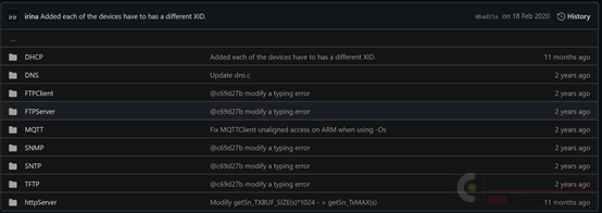
The W5500 driver library can be downloaded from GitHub: https://github.com/Wiznet/ioLibrary_Driver
This is the structure of my newly created W5500 project.
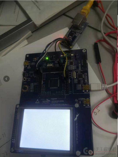
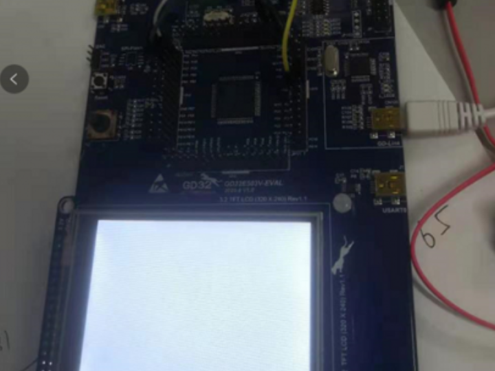
The hardware connection interfaces are as follows:
PA7—>W5500_MOSI
PA6—>W5500_MISO
PA5—>W5500_SCK
PE3—>W5500_CS
PE6—>W5500_RST
During debugging, I also discovered a problem. Because the W5500 I'm debugging this time is composed of modules, I'm using DuPont wires to connect it to the development board. In previous projects, the W5500 was directly laid out onto the board. The same program ran perfectly on the STM32, but it just wouldn't run on this development board... After endless troubleshooting, the problem turned out to be with the DuPont wires. It seems the DuPont wires I was using were of poor quality (by the way, it's impossible to find good quality DuPont wires on Taobao; if any forum members have recommendations, please let me know, thanks!). Later, I used a different type of DuPont wire, and it worked. I was initially confident that debugging would only take half a day, but I ended up wasting at least three days on this problem...
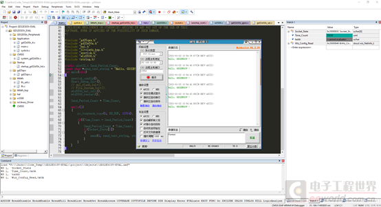
In the main loop, I created a Socket Server service on port 12345. Connecting to it using a network debugging tool allows for bidirectional data transmission. Those interested can download the complete project code for reference.