
Ethernet NIC debugging physical layer precautions
Ethernet NIC debugging physical layer precautions
A common way to verify network interface communication is through a ping test. To test ping, you can use a previously verified upper-layer program.
If ping fails, hardware issues need to be investigated.
Most chips use an on-chip MAC (Machine Interface) and an off-chip PHY (Physical Interface). First, the PHY is configured via the MDIO interface; you read and write the PHY to perform the configuration. If this step is normal, check the data interface . The data interface is usually an RGMII, RMII, or similar interface. The voltage between the MAC and PHY needs to be matched.
A transformer may need to be connected after the PHY, and it is also necessary to pay attention to whether the transformer is voltage-controlled or current-controlled.
The following two examples are ones I have encountered.
1 YT8521 network card
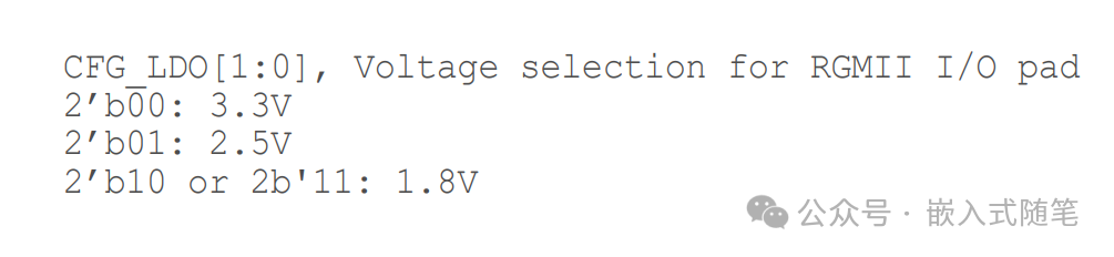
The MAC I/O voltage is 1.8V, but the actual measured voltage is 1.2V. The PHY voltage needs to be configured.
If not configured, the problem is that pinging will fail, or if it does succeed occasionally after powering on, the latency will be very high.
The network card can be configured via external pins. See the diagram below.

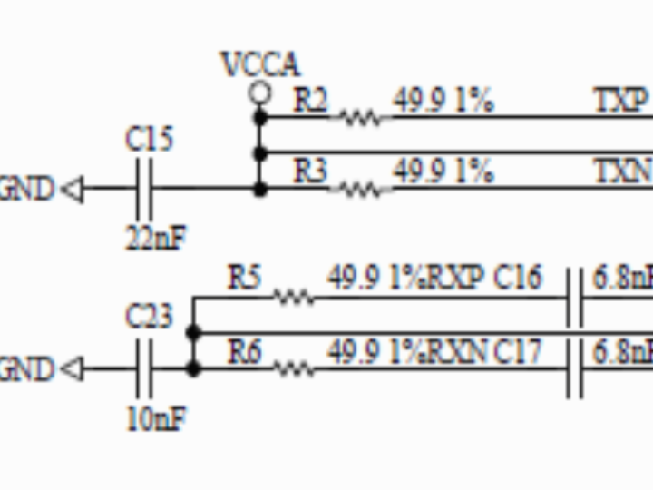
2 W5500 network cards
The recommended schematic for connecting the W5500 transformer is shown below. The receiver and transmitter are driven by current and voltage respectively; one is connected to a power source, and the other is not. This differs from many common PHYs, which are mostly voltage-driven or current-driven.

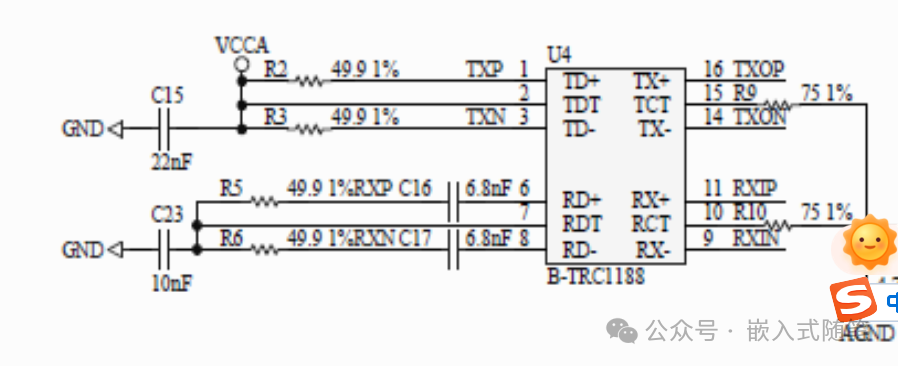
If the connection is incorrect, the adaptive mode will only negotiate to half-duplex, and pinging will fail even at 100Mbps. Forcing it to 10Mbps full-duplex via software will allow pinging to succeed.
These are two different phenomena. If ping fails, you can troubleshoot from a hardware perspective by checking similar aspects.