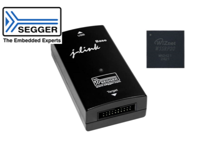
Connecting the W55RP20 Using SEGGER [J-Link]
SEGGER [J-Link] supports the W55RP20.

We'll walk you through the process of setting up a microcontroller unit (MCU) using J-Link in detail. Follow these steps to ensure a smooth setup.
1. Check what you need
- J-Link Debugger: J-Link debugging tool provided by SEGGER.
- MCU Development Board: Development board with target MCU.
- USB cable: Cable to connect the J-Link to the PC.
- J-Link Software Package: Available for download from SEGGER's official website.
- Communication interface cable: Cable for connecting the MCU and J-Link, such as SWD, JTAG, etc. (depending on the development board).
2. Install J-Link Software and Drivers
- Visit the SEGGER official website: Access the SEGGER J-Link download page.
- SEGGER - The Embedded Experts - Downloads - J-Link / J-Trace
- Download the software: Download the J-Link software package for your operating system.
- Run the installation file: Run the downloaded installation file and follow the on-screen instructions to complete the installation.
- Confirm Driver Installation: The installation process will automatically install the drivers, and it is recommended that you reboot your PC after the installation is complete.
3. Connect the J-Link and MCU
- J-Link Connection: Connect the J-Link device to the PC using a USB cable.
- MCU Connection: Connect the J-Link to the MCU using the debugging port (SWD, JTAG, etc.) on the development board.
- Make sure the power supply and GND connections are correct when connecting.
- Verify the connection: Verify that the J-Link software recognizes the J-Link device. You can run J-Flash to check the connection status.
4. J-Link Software Setup
- First, create a project.
- After running the program, J-Link needs to specify the model of the target MCU, we specify W55RP20.
- Interface settings:
Set the communication interface (SWD) with the MCU.
Set Speed: Set the debugging speed. Typically, you use the default speed (for example, 4000 kHz), but you can adjust it as needed.
5. Test the connection
- Verify device connectivity: Enter the connect command to verify that the J-Link connects to the MCU normally. If successful, the information of the MCU will be output.
- Memory Read/Write Test: A simple memory read/write command can be used to further verify the connection status.You can read the address 0x10000000 to get the value.
References
- SEGGER J-Link Official Manual: Refer to the official manual available on the SEGGER website for more detailed information.
- Development board manuals: Refer to the manual for the MCU development board you are using to understand pin connections and settings.
- Online communities and forums: You can get additional help from communities that share experiences from developers using the same MCU and J-Link.
- Follow these steps to successfully register your J-Link and MCU and set up your debugging environment

