



Prvin-Embed/Aerostat-GCS-ESP32-TelemetryHub
An aerostat is not a drone. It is a balloon-type platform anchored to the ground by a mooring cable (tether), holding a fixed position at altitudes of tens to
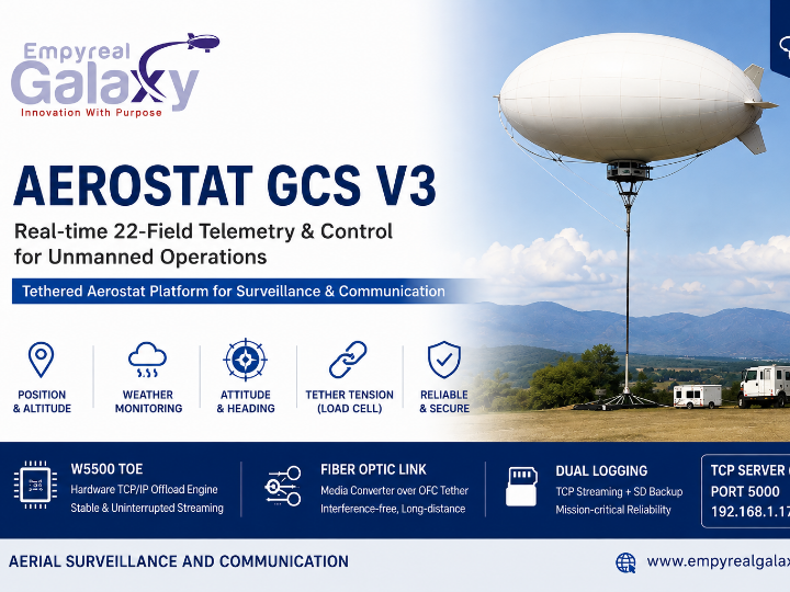
A W5500 Telemetry Hub That Enables 24/7 Monitoring of a Tethered Aerostat — Empyreal Galaxy's Aerostat GCS V3
What Is an Aerostat, and Why Does It Need Ground Control?
An aerostat is not a drone. It is a balloon-type platform anchored to the ground by a mooring cable (tether), holding a fixed position at altitudes of tens to hundreds of meters for extended periods. It does not return home when a battery runs low like a drone, nor does it drift away with the wind like a free-floating weather balloon. Staying above the same coordinates for days or weeks of unattended, continuous operation — that is the aerostat's entire reason for being.
This characteristic, however, creates three problems for operators.
- Out-of-sight operation: The platform is airborne and unmanned. Sudden temperature swings, abnormal wind speeds, or tether tension overloads can occur with no immediate way to know from the ground.
- No instant recovery: There is no RTH (Return-to-Home) command like a drone's. When something goes wrong, crews must physically winch the cable in — which means early warning is equipment preservation.
- Reliability for unattended long-duration operation: As the same team's related project (Aerostat Mega Sensor Hub) puts it, "a crash that requires manual intervention is not an inconvenience — it is an operational failure."
Empyreal Galaxy's Aerostat GCS V3 firmware answers these problems with 22-field real-time telemetry + W5500 TCP streaming + dual SD logging. Every two seconds, the airborne platform reports its position, altitude, weather, attitude, and cable tension to the ground — effectively an industrial remote-sensing node floating in the sky.
About the Maker — Empyreal Galaxy Pvt. Ltd.
Empyreal Galaxy is a Lighter-Than-Air (LTA) aircraft startup headquartered in Goregaon, Mumbai, India, with overseas offices in New York and London. It is a deep-tech company supported by the Atal Incubation Centre (AIC-RMP) Mumbai and by SINE at IIT Bombay, one of India's premier engineering-school incubators.
| Solution | Description |
|---|---|
| Surveillance & reconnaissance aerostats | High-altitude, long-endurance monitoring platforms for defense and security |
| Communication relay balloons | Rapid deployment of temporary communication infrastructure in remote or disaster areas |
| Airship-based emergency delivery | Aerial delivery of food, medicine, and blood packs within a 100 km radius (hybrid system with onboard drones) |
Guided by the belief that "technology and innovation must solve real, complex problems and create positive impact," the company is developing eco-friendly aircraft powered by solar energy and biodiesel. This GCS V3 firmware is a core component of the company's own operational system for real-time ground control of surveillance and communication aerostats, released under the MIT license.
WIZnet Product Used
| Product | Interface | Pins | Role |
|---|---|---|---|
| W5500 | SPI | SCK=18, MISO=19, MOSI=23, CS=5 | Hardware TCP server — real-time 22-field CSV streaming to the GCS |
The W5500's TOE (TCP/IP Offload Engine) handles the entire network stack in silicon, leaving the ESP32 CPU fully dedicated to aggregating, timestamping, and assembling CSV data from its four data sources (the Arduino Mega UART bridge, BNO055, DHT22, and the RS485 anemometer).
Why a WIZnet Chip — Optical Fiber Inside the Tether
The tether connecting the aerostat to the ground is more than a mooring line. According to documentation from the same author's related project, the team embeds an optical fiber cable (OFC) inside the tether and uses it as the data link.
The roles of each component are cleanly separated here. The W5500 is the protocol processor — it handles the TCP/IP stack in hardware and outputs standard copper Ethernet. A media converter translates that Ethernet signal into an optical signal, and the OFC is the transmission medium. The W5500 does not drive the fiber directly.
Why this wired arrangement replaces Wi-Fi and RF radio:
| Criterion | Wi-Fi / RF Wireless | W5500 + Media Converter + OFC |
|---|---|---|
| Interference at altitude | Signal unstable with altitude, obstacles, and weather | Physical link — no interference |
| Bandwidth stability | Degrades with distance | Stable regardless of cable length |
| Latency | Varies with retransmission and contention | Deterministic, consistent delay |
| RF regulation | May require frequency licensing in the operating region | Wired — no licensing needed |
| MCU load | Requires a software TCP/IP stack | Handled in hardware by the W5500 TOE — zero load on the ESP32 |
The last row is what makes the whole system viable. Had the ESP32 run its TCP server on a software stack (lwIP), it would struggle to poll four sources simultaneously while sustaining an uninterrupted stream. Maintaining the continuous, no-drop data stream that defense and surveillance missions demand — without software intervention — is precisely the W5500 TOE's job.
System Architecture
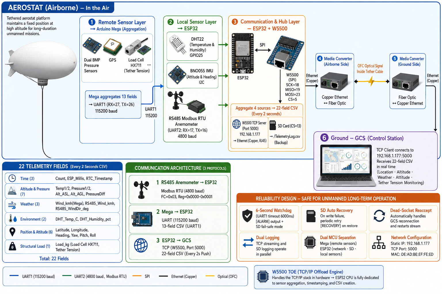
The 22 Telemetry Fields — the Aerostat's Vital Signs
The 22 CSV fields specified in the README read like an aerostat operations checklist.
| Category | Fields | Operational Meaning |
|---|---|---|
| Time | Count, ESP_Millis, RTC_Timestamp | Data continuity check, packet-loss detection |
| Altitude & pressure | Dual BMP: Temp1/2, Pressure1/2, Alt_ASL/Alt_AGL, PressureDiff | Dual altitude (above sea level / above ground), ascent/descent anomaly detection |
| Weather | Wind_kmh (Mega side) + RS485_Wind_kmh, RS485_WindDir_deg | Wind measurement redundant across two channels — judging whether operating limits are exceeded |
| Environment | DHT_Temp_C, DHT_Humidity_pct | Verifying payload equipment stays within its operating temperature range |
| Position & attitude | Latitude, Longitude, Heading, Yaw, Pitch, Roll | Position drift and attitude anomaly detection |
| Structural load | Load_kg (HX711 load cell) | Tether tension — the aerostat's unique safety metric |
Of these, load-cell-based tether tension measurement is the decisive difference from ordinary IoT telemetry. When wind speed spikes, drag on the balloon rises and the tether pulls taut. Because tension is part of the live CSV, ground operators can decide to winch the platform down before the cable approaches its limit. The aerostat operations philosophy — "early warning is equipment preservation" — is condensed into a single data field.
Hardware Configuration
| Component | Interface | Pins | Role |
|---|---|---|---|
| W5500 (WIZnet) | SPI | SCK=18, MISO=19, MOSI=23, CS=5 | TCP server — Ethernet streaming to the GCS |
| Arduino Mega | UART1 (115200 baud) | RX=27, TX=26 | Aggregated 13-field sensor feed (dual BMP · GPS · load cell) |
| RS485 Modbus anemometer | UART2 (4800 baud) | RX=17, TX=16 | Wind speed & direction (Modbus RTU, FC=0x03, Reg=0x0000·0x0001) |
| DHT22 | GPIO | 25 | Temperature & humidity |
| BNO055 IMU | I2C | SDA/SCL | Attitude (Yaw · Pitch · Roll) |
| SD card | SPI | CS=13 | Local CSV backup (/TelemetryLog.csv) |
Network configuration: Static IP 192.168.1.177 / TCP port 5000 / MAC DE:AD:BE:EF:FE:ED
Communication Design — Three Protocols, Layered
| Segment | Protocol | Details | Why This Choice |
|---|---|---|---|
| RS485 anemometer → ESP32 | Modbus RTU (4800 baud) | FC=0x03, registers 0x0000·0x0001 | Industrial standard — connects an off-the-shelf weather instrument with no custom driver |
| Arduino Mega → ESP32 | UART (115200 baud) | 13-field CSV over UART1 | Low-latency inter-MCU link |
| ESP32 → Ground GCS | TCP socket (W5500, port 5000) | One 22-field CSV line pushed every 2 s | Standard TCP — any client works: nc, a Python socket, a custom app |
Choosing plain TCP means the GCS software needs no proprietary SDK or driver. On the ground, connecting a laptop to the same LAN and opening a socket to 192.168.1.177:5000 is all it takes to start the live stream. Skipping an aviation-specific protocol like MAVLink appears to be a deliberate choice favoring universal compatibility (not stated in the README — inferred from the architecture).
Implementation & Reliability Design
Data flow:
Arduino Mega (UART1, 115200 baud: 13 fields — dual BMP · GPS · load cell)
  + BNO055 IMU (I2C)
  + DHT22 (GPIO 25)
  + RS485 Modbus anemometer (UART2, 4800 baud)
        ↓ ESP32 aggregation → timestamping → 22-field CSV (every 2 s)
        ├─ W5500 TCP server (port 5000)
        │    → Ethernet (copper) → media converter (airborne)
        │    → OFC optical signal (inside tether) → media converter (ground)
        │    → Ethernet (copper) → GCS TCP client
        └─ SD card (CS=13, /TelemetryLog.csv, append mode) — parallel logging
Reliability design — a safety net for unattended long-duration operation:
For a system that goes days without human hands, half the firmware exists for the moment something fails.
| Mechanism | Behavior | Effect |
|---|---|---|
6-second watchdog (MEGA_TIMEOUT_MS) | 6000 ms of UART1 silence → prints [ALARM] + switches to SD failsafe | Detects a Mega disconnect or crash within 6 seconds |
SD auto-recovery (SD_RETRY_MS) | Periodic retries after a write failure; [RECOVERY] tag on success | Automatic return from transient SD errors |
| Dead-socket re-accept | Non-blocking polling handles GCS reconnection automatically | Stream resumes on its own after a ground-terminal restart or network drop |
| Dual logging | TCP streaming and SD recording always run in parallel | Flight data survives network outages |
| Dual-MCU separation | Mega (remote sensor aggregation) / ESP32 (network · SD · direct sensors) | A failure on one side cannot drag down the other |
Build environment: Arduino IDE. W5500 initialization order: Ethernet.init(CS=5) → Ethernet.begin(mac, ip) → server.begin().
Dependencies (all open source):
| Library | Purpose |
|---|---|
| Adafruit DHT sensor library | DHT22 temperature & humidity |
| EasyBNO055_ESP | BNO055 IMU |
| ModbusMaster | RS485 Modbus RTU anemometer |
| Ethernet (Arduino) | W5500 TCP server |
| SD | SD card CSV logging |
Project Value & Broader Applications
The core pattern this project demonstrates is "a remote platform connected by a physical cable (tether/OFC) + a W5500 TCP server + multi-interface sensor aggregation" — real-time ground control for environments where wireless is impossible or untrustworthy. The same design transplants directly into any system where a physical cable links a platform to the ground:
- Surface drones and underwater ROVs: Add an Ethernet pair to the control tether for real-time sensor streaming
- Cable car and crane structural monitoring: Stream wire-rope tension plus environmental data to a control room over TCP
- Communication relay balloons: Reuse the same hub to monitor the health of comms equipment carried by an aerostat
- Weather observation towers: Aggregate multi-altitude sensors with a Mega → stream to a weather server via ESP32 + W5500
The RS485 Modbus RTU → W5500 Ethernet bridge pattern is also a general-purpose recipe, reusable as-is whenever legacy Modbus equipment on an industrial site needs to join an Ethernet network.
Q&A
Q1. Why this arrangement (W5500 + media converter + OFC) instead of Wi-Fi?
According to the same author's related project, an optical fiber cable (OFC) inside the tether serves as the ground-to-balloon data link. The roles are separated: the W5500 processes TCP/IP in hardware and outputs copper Ethernet, and a media converter translates it to an optical signal for the OFC. At altitudes of hundreds of meters, wireless can become unstable with distance, weather, and obstructions — but this wired arrangement is a physical link, guaranteeing interference-free, deterministic streaming with no RF licensing concerns.
Q2. Why use both an Arduino Mega and an ESP32?
Separation of duties. The Mega focuses on polling the remote sensors placed around the airframe (dual BMP pressure, GPS, load cell) and aggregating them into 13 fields, while the ESP32 handles its directly attached sensors (BNO055, DHT22, RS485 anemometer) plus networking and SD. A single MCU juggling all sensor polling and a TCP server would lose real-time performance — and with the W5500 TOE added, even the ESP32 is freed from the TCP stack burden (presumed to be a design decision from the V1→V3 evolution — not explicitly stated in the README).
Q3. Why measure tether tension with a load cell?
It is the aerostat's own safety metric. When wind speed exceeds a threshold, drag on the balloon surges and excessive tension builds in the tether. Because the tension value is part of the live CSV, ground operators can decide to recover the platform before the cable reaches its limit.
Q4. Why did Empyreal Galaxy release this firmware publicly?
Empyreal Galaxy is a startup backed by the SINE incubator at IIT Bombay, commercially developing aerostats for defense, surveillance, and disaster response. This GCS V3 firmware is a portion of the company's own operational system released under the MIT license, and the same GitHub account hosts several related aerostat projects.
Q5. Do SD backup and TCP streaming run at the same time?
Always, in parallel. CSV is written to SD simultaneously with TCP streaming, so flight data is preserved even if the GCS connection drops. Additionally, if the Mega link is lost (triggering the 6-second watchdog), the system switches to SD failsafe mode.
기구(Aerostat)란 무엇이고, 왜 지상 관제가 필요한가
Aerostat(에어로스탯)은 드론이 아니다. 계류 케이블(테더)로 지상에 묶인 채 수십~수백 미터 고도에서 장시간 고정 위치를 유지하는 기구형 플랫폼이다. 드론처럼 배터리가 다하면 복귀하는 것도 아니고, 자유 부양 기상 기구처럼 바람에 떠내려가는 것도 아니다. 같은 좌표 위에서 며칠, 몇 주씩 무인 연속 운용하는 것 — 그것이 Aerostat의 존재 이유다.
그런데 이 특성이 운용자에게 세 가지 문제를 만든다.
- 시야 밖 운용: 기구는 공중에, 장비는 무인 상태로 떠 있다. 온도 급변, 풍속 이상, 테더 장력 과부하가 발생해도 지상에서 즉시 알 방법이 없다.
- 즉각 대응 불가: 드론의 RTH(Return-to-Home) 같은 자동 복귀 명령이 없다. 이상 징후가 보이면 인력이 케이블을 감아 회수해야 하므로, 조기 경보가 곧 장비 보전이다.
- 무인 장기 운용의 신뢰성: 동일 팀의 관련 프로젝트(Aerostat Mega Sensor Hub)가 명시하듯, "크래시가 수동 개입을 요구하는 상황은 불편함이 아니라 운용 불가 상황"이다.
Empyreal Galaxy의 Aerostat GCS V3 펌웨어는 그 해답으로 22-필드 실시간 텔레메트리 + W5500 TCP 스트리밍 + SD 이중 로깅을 구현했다. 공중의 기구가 자신의 위치·고도·기상·자세·케이블 장력을 2초마다 지상에 보고하는, '하늘에 떠 있는 산업용 원격 계측 노드'다.
제작사 소개 — Empyreal Galaxy Pvt. Ltd.
Empyreal Galaxy는 인도 뭄바이(Goregaon) 기반의 경량 비행선(Lighter-Than-Air Aircraft) 스타트업으로, 미국 뉴욕·영국 런던에 해외 사무소를 두고 있다. Atal Incubation Centre(AIC-RMP) 뭄바이와 인도 최고 공과대학 인큐베이터인 IIT Bombay SINE의 지원을 받는 딥테크 기업이다.
| 솔루션 | 내용 |
|---|---|
| 감시·정찰 에어로스탯 | 국방·보안 분야 고고도 장기 감시 플랫폼 |
| 통신 중계 기구 | 원격지·재난지역 통신 인프라 임시 구축 |
| 비행선 기반 긴급 배송 | 100km 반경 내 식량·의약품·혈액팩 항공 배송 (드론 탑재 혼합 시스템) |
"기술과 혁신이 실제 복잡한 문제를 해결하고 긍정적 영향을 창출해야 한다"는 철학 아래 태양광·바이오디젤 기반 친환경 비행체를 개발 중이며, 이번 GCS V3 펌웨어는 감시·통신 임무용 에어로스탯을 실시간 관제하는 자체 운용 시스템의 핵심 구성 요소를 MIT 라이선스로 공개한 것이다.
사용 WIZnet 제품
| 제품 | 인터페이스 | 핀 | 역할 |
|---|---|---|---|
| W5500 | SPI | SCK=18, MISO=19, MOSI=23, CS=5 | 하드웨어 TCP 서버 — GCS로 22-필드 CSV 실시간 스트리밍 |
W5500의 TOE(TCP/IP Offload Engine)가 네트워크 스택을 칩 하드웨어에서 직접 처리하므로, ESP32 CPU는 4개 데이터 소스(Mega UART 브리지, BNO055, DHT22, RS485 풍속계)의 집계·타임스탬핑·CSV 조립에 온전히 집중할 수 있다.
WIZnet 칩 선택 이유 — 테더 케이블 안의 광섬유
기구와 지상을 연결하는 테더는 단순한 계류줄이 아니다. 동일 저자의 관련 프로젝트 문서에 따르면, 이 팀은 테더 내부에 광섬유 케이블(OFC, Optical Fiber Cable) 을 삽입해 데이터 링크로 활용한다.
여기서 각 구성 요소의 역할은 명확히 분리된다. W5500은 TCP/IP 스택을 하드웨어로 처리해 표준 이더넷(구리선)을 출력하는 프로토콜 처리기이고, 미디어 컨버터가 그 이더넷 신호를 광신호로 변환하며, OFC는 전송 매체다. W5500이 광섬유를 직접 구동하는 것이 아니다.
이 유선 구성이 Wi-Fi·RF 무선을 대체하는 이유:
| 비교 항목 | Wi-Fi / RF 무선 | W5500 + 미디어 컨버터 + OFC |
|---|---|---|
| 고도 간섭 | 고도·장애물·날씨에 따라 신호 불안정 | 물리 링크 — 간섭 없음 |
| 대역폭 안정성 | 거리 증가 시 감소 | 케이블 길이와 무관하게 안정 |
| 레이턴시 | 재전송·경쟁 시 지연 변동 | 결정론적, 일정한 지연 |
| RF 규제 | 운용 지역 주파수 허가 필요 가능 | 유선 — 규제 불필요 |
| MCU 부하 | 소프트웨어 TCP/IP 스택 필요 | W5500 TOE가 하드웨어 처리 — ESP32 부하 없음 |
특히 마지막 항목이 이 시스템의 성립 조건이다. ESP32가 소프트웨어 TCP/IP(lwIP)로 서버를 구동했다면, 4개 소스를 동시에 폴링하면서 무중단 스트림을 유지하기 어렵다. 국방·감시 임무가 요구하는 끊김 없는 데이터 스트림을 소프트웨어 개입 없이 유지하는 것 — 그것이 W5500 TOE의 역할이다.
시스템 계층 구조
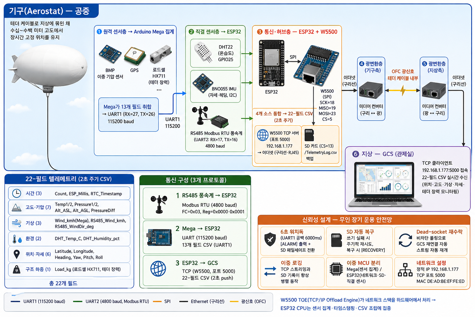
22개 텔레메트리 필드 — 기구의 '생체 신호'
README에 명시된 22개 CSV 필드는 그대로 기구 운용 체크리스트다.
| 카테고리 | 필드 | 운용상 의미 |
|---|---|---|
| 시간 | Count, ESP_Millis, RTC_Timestamp | 데이터 연속성 확인, 패킷 손실 감지 |
| 고도·기압 | BMP 이중: Temp1/2, Pressure1/2, Alt_ASL/Alt_AGL, PressureDiff | 해발/지상 기준 이중 고도 산출, 상승·하강 이상 감지 |
| 기상 | Wind_kmh(Mega측) + RS485_Wind_kmh, RS485_WindDir_deg | 풍속 계측이 두 계통으로 이중화 — 운용 한계 초과 여부 판단 |
| 환경 | DHT_Temp_C, DHT_Humidity_pct | 탑재 장비 동작 온도 범위 확인 |
| 위치·자세 | Latitude, Longitude, Heading, Yaw, Pitch, Roll | 위치 이탈, 자세 이상 감지 |
| 구조 하중 | Load_kg (로드셀 HX711) | 테더 장력 — 기구 고유의 안전 지표 |
이 중 로드셀 기반 테더 장력 측정이 일반 IoT 텔레메트리와의 결정적 차이다. 풍속이 급증하면 기구에 걸리는 항력이 커지고 테더가 당겨진다. 장력 수치가 실시간 CSV에 포함되어 있기 때문에, 지상 운용자는 케이블이 한계에 도달하기 전에 회수 결정을 내릴 수 있다. "조기 경보가 곧 장비 보전"이라는 Aerostat 운용 철학이 데이터 필드 하나에 응축되어 있다.
하드웨어 구성
| 컴포넌트 | 인터페이스 | 핀 | 역할 |
|---|---|---|---|
| W5500 (WIZnet) | SPI | SCK=18, MISO=19, MOSI=23, CS=5 | TCP 서버 — GCS 이더넷 스트리밍 |
| Arduino Mega | UART1 (115200 baud) | RX=27, TX=26 | 13-필드 센서 집계 전송 (듀얼 BMP·GPS·로드셀) |
| RS485 Modbus 풍속계 | UART2 (4800 baud) | RX=17, TX=16 | 풍속·풍향 (Modbus RTU, FC=0x03, Reg=0x0000·0x0001) |
| DHT22 | GPIO | 25 | 온도·습도 |
| BNO055 IMU | I2C | SDA/SCL | 자세 (Yaw·Pitch·Roll) |
| SD 카드 | SPI | CS=13 | 로컬 CSV 백업 (/TelemetryLog.csv) |
네트워크 설정: 정적 IP 192.168.1.177 / TCP 포트 5000 / MAC DE:AD:BE:EF:FE:ED
통신 구성 — 세 프로토콜의 계층적 조합
| 구간 | 프로토콜 | 상세 | 선택 이유 |
|---|---|---|---|
| RS485 풍속계 → ESP32 | Modbus RTU (4800 baud) | FC=0x03, 레지스터 0x0000·0x0001 | 산업 표준 — 상용 기상 장비를 별도 드라이버 없이 직결 |
| Arduino Mega → ESP32 | UART (115200 baud) | 13개 필드 CSV, UART1 | 저지연 MCU 간 통신 |
| ESP32 → 지상 GCS | TCP 소켓 (W5500, 포트 5000) | 22-필드 CSV 한 줄씩 2초 push | 표준 TCP — nc, Python socket, 커스텀 앱 등 어떤 클라이언트도 수신 가능 |
표준 TCP를 택한 덕에 GCS 소프트웨어에 전용 SDK나 드라이버가 필요 없다. 지상에서는 같은 LAN에 노트북을 연결하고 192.168.1.177:5000에 소켓을 여는 것만으로 라이브 스트림이 시작된다. MAVLink 같은 항공 전용 프로토콜을 도입하지 않은 것은 범용 호환성을 우선한 설계 선택으로 보인다 (README 명시 없음 — 구조에서 유추).
구현 방법 / 신뢰성 설계
데이터 흐름:
Arduino Mega (UART1 115200 baud: 13필드 — 듀얼 BMP·GPS·로드셀)
  + BNO055 IMU (I2C)
  + DHT22 (GPIO 25)
  + RS485 Modbus 풍속계 (UART2 4800 baud)
        ↓ ESP32 집계 → 타임스탬프 부착 → 22-필드 CSV (2초 주기)
        ├─ W5500 TCP 서버 (포트 5000)
        │    → 이더넷(구리선) → 미디어 컨버터(기구측)
        │    → OFC 광신호(테더 내부) → 미디어 컨버터(지상측)
        │    → 이더넷(구리선) → GCS TCP 클라이언트
        └─ SD 카드 (CS=13, /TelemetryLog.csv, append 모드) — 병렬 로깅
신뢰성 설계 — 무인 장기 운용 안전망:
며칠씩 사람 손이 닿지 않는 시스템이므로, 펌웨어의 절반은 '실패했을 때'를 위한 코드다.
| 메커니즘 | 동작 | 효과 |
|---|---|---|
6초 워치독 (MEGA_TIMEOUT_MS) | UART1 공백 6000ms → [ALARM] 출력 + SD 페일세이프 전환 | Mega 단선·크래시를 6초 내 감지 |
SD 자동 복구 (SD_RETRY_MS) | 쓰기 실패 후 주기적 재시도, 복구 시 [RECOVERY] 태그 | 일시적 SD 오류에서 자동 복귀 |
| Dead-socket 재수락 | 비차단 폴링으로 GCS 재연결 자동 처리 | 지상 단말 재시작·네트워크 단절 후 스트림 자동 재개 |
| 이중 로깅 | TCP 스트리밍과 SD 기록이 항상 병렬 동작 | 네트워크 장애에도 비행 데이터 보존 |
| 이중 MCU 분리 | Mega(원격 센서 집계) / ESP32(네트워크·SD·직결 센서) | 한쪽 장애가 다른 쪽을 끌고 넘어지지 않음 |
빌드 환경: Arduino IDE. W5500 초기화 순서는 Ethernet.init(CS=5) → Ethernet.begin(mac, ip) → server.begin().
의존 라이브러리 (모두 오픈소스):
| 라이브러리 | 용도 |
|---|---|
| Adafruit DHT sensor library | DHT22 온습도 |
| EasyBNO055_ESP | BNO055 IMU |
| ModbusMaster | RS485 Modbus RTU 풍속계 |
| Ethernet (Arduino) | W5500 TCP 서버 |
| SD | SD 카드 CSV 기록 |
프로젝트 가치 / 적용 확장
이 프로젝트의 핵심 패턴은 "물리 케이블(테더/OFC)로 연결된 원격 플랫폼 + W5500 TCP 서버 + 다중 인터페이스 센서 집계" 구조로, 무선이 불가능하거나 신뢰할 수 없는 환경의 실시간 지상 관제를 구현한다는 것이다. 물리 케이블로 플랫폼과 지상이 이어지는 모든 시스템에 그대로 이식할 수 있다.
- 수상 드론·수중 ROV: 제어 테더에 이더넷 페어를 추가해 실시간 센서 스트리밍
- 케이블카·크레인 구조 모니터링: 와이어 로프 장력 + 환경 데이터를 TCP로 관제실 전송
- 통신 중계 기구: 에어로스탯 탑재 통신 장비의 상태 모니터링에 동일 허브 재사용
- 기상 관측 타워: 다중 고도 센서를 Mega로 집계 → ESP32 + W5500으로 기상 서버 스트리밍
또한 RS485 Modbus RTU → W5500 이더넷 브리지 패턴은 산업 현장의 레거시 Modbus 장비를 이더넷 망에 올릴 때 그대로 재사용 가능한 범용 레시피다.
Q&A
Q1. Wi-Fi 대신 이 구성(W5500 + 미디어 컨버터 + OFC)을 선택한 이유는?
동일 저자의 관련 프로젝트에 따르면 테더 케이블 내부의 광섬유(OFC)가 지상-기구 간 데이터 링크다. 역할은 분리된다: W5500이 TCP/IP를 하드웨어로 처리해 이더넷(구리선)을 출력하고, 미디어 컨버터가 이를 광신호로 변환해 OFC로 전송한다. 수백 미터 고도에서 무선은 거리·날씨·장애물에 따라 불안정해질 수 있지만, 이 유선 구성은 물리 링크이므로 간섭 없는 결정론적 스트리밍을 보장하며 RF 주파수 규제에서도 자유롭다.
Q2. Arduino Mega와 ESP32를 이중으로 사용하는 이유는?
역할 분리 때문이다. Mega는 기체 곳곳에 배치된 원격 센서(듀얼 BMP 기압, GPS, 로드셀)를 폴링해 13개 필드로 집계하는 데 집중하고, ESP32는 직결 센서(BNO055, DHT22, RS485 풍속계) 처리와 네트워크·SD를 담당한다. 하나의 MCU가 전체 센서 폴링과 TCP 서버를 겸하면 실시간성이 무너진다 — 여기에 W5500 TOE가 더해져 ESP32조차 TCP 스택 부담에서 해방된다 (V1→V3 진화 과정의 설계 결정으로 추정 — README 직접 명시 없음).
Q3. 로드셀로 테더 장력을 측정하는 이유는?
기구 전용 안전 지표다. 풍속이 임계값을 넘으면 기구에 걸리는 항력이 커져 테더에 과도한 장력이 걸린다. 장력 수치가 실시간 CSV에 포함되므로 지상 운용자가 케이블 한계 도달 전에 회수를 결정할 수 있다.
Q4. Empyreal Galaxy는 이 펌웨어를 어떤 목적으로 공개했나?
Empyreal Galaxy는 IIT Bombay SINE 인큐베이터 지원을 받으며 국방·감시·재난 대응용 에어로스탯을 상용 개발 중인 스타트업이다. 이 GCS V3 펌웨어는 자사 운용 시스템의 일부를 MIT 라이선스로 공개한 것으로, 같은 GitHub 계정에 다수의 관련 에어로스탯 프로젝트가 존재한다.
Q5. SD 카드 백업과 TCP 스트리밍이 동시에 작동하는가?
항상 병렬 동작한다. TCP 스트리밍과 동시에 SD에도 CSV를 기록하므로 GCS 연결이 끊겨도 비행 데이터가 보존되고, Mega 링크 단절(6초 워치독 발동) 시에는 SD 페일세이프 모드로 전환된다.