



PLC_PRS10
PLC_PRS10
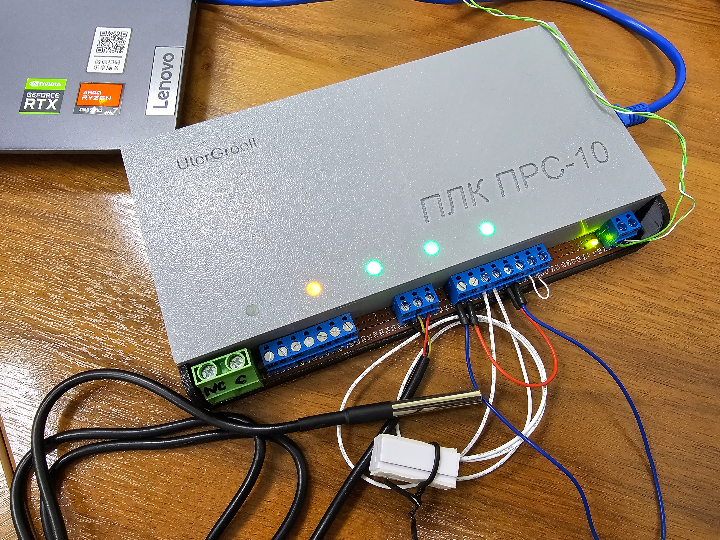
PLC_PRS10 — Arduino Modbus TCP Slave Controller for SCADA with W5100/W5500 and Ethernet Watchdog
Tags: W5100 · W5500 · Arduino · Modbus TCP · SCADA · PLC · DS18B20 · Relay Control · Industrial IoT
Overview
PLC_PRS10 is a compact, open-source PLC-style controller built on Arduino and WIZnet W5100/W5500 Ethernet. It acts as a Modbus TCP Slave device, exposing two relay outputs, a DS18B20 temperature reading, and four discrete digital inputs to any SCADA system — all over standard Modbus TCP on port 502.
The project is intentionally minimal: no RTOS, no cloud dependency, no configuration portal. It plugs into an existing Ethernet network, announces itself at a fixed IP, and immediately speaks Modbus TCP — the lingua franca of industrial automation. Tested with Rapid SCADA and Modbus Poll, it fits naturally into any supervisory control environment that supports Modbus TCP/IP.
A custom Modbus library (ModbusTCP_RU) handles the protocol stack, including a split Modbus data model that keeps coils, discrete inputs, and input registers in separate address spaces.
Hardware Platform
| Component | Description |
|---|---|
| MCU | Arduino (ATmega328P) |
| Ethernet | WIZnet W5100 or W5500 — SPI, CS on D10 |
| Relay outputs | 2× relay — D7 (Relay 1), D6 (Relay 2) |
| Digital inputs | 4× discrete input — D2 / D3 / D4 / D5, INPUT_PULLUP |
| Temperature | DS18B20 1-Wire sensor on D9 |
| Protocol | Modbus TCP, port 502, Slave ID 1 |

How WIZnet W5100/W5500 is Used
The W5100 or W5500 (selectable at hardware level — both are pin-compatible on SPI) is the only network interface in PLC_PRS10. It provides the full TCP/IP stack in hardware, so the Arduino's ATmega328P only needs to write and read socket data — no software networking code.
1. Modbus TCP Server

On startup, the firmware initialises the WIZnet chip with a static IP and immediately opens a Modbus TCP server on port 502:
byte mac[] = { 0xDE, 0xDD, 0xBE, 0xEF, 0xFE, 0x01 };
IPAddress ip(192, 168, 1, 179);
Ethernet.begin(mac, ip, gateway, subnet);
MbServer.begin();
From this point the device is addressable by any SCADA system as a standard Modbus TCP slave. The SCADA polls at 1000 ms scan rate with a 1000 ms timeout — well within what the W5100/W5500 can handle while the Arduino simultaneously manages relay timing, debounces inputs, and reads the DS18B20.
2. Ethernet Watchdog — Link Recovery Without Reboot
One of the most practical engineering decisions in this project is the Ethernet link watchdog. When a patch cord is disconnected and reconnected, the W5100/W5500 may respond to ARP/ping again, but its internal TCP server socket does not automatically recover — the SCADA master loses the Modbus TCP connection and the Arduino must be manually rebooted to restore it.
The watchdog solves this by monitoring the W5100/W5500 link status bit. When LinkON is detected after a link loss, the firmware reinitialises the Ethernet stack and restarts the Modbus server without rebooting the board:
if (Ethernet.linkStatus() == LinkON && !linkWasOn) {
    Ethernet.begin(mac, ip, gateway, subnet);
    MbServer.begin();
    linkWasOn = true;
 }
This is critical for unattended deployment in cabinets or remote panels where physical reboots are not practical.
Modbus Register Map
The firmware uses the ModbusTCP_RU library, which implements a split data model — coils, discrete inputs, and input registers occupy separate address spaces, matching standard Modbus conventions.

Coils — FC01 (read) / FC05 or FC15 (write)
| Address | Signal | Values |
|---|---|---|
0 | Relay 1 (D7) | 0 = OFF, 1 = ON |
1 | Relay 2 (D6) | 0 = OFF, 1 = ON |
Relay 1 includes a hardware safety timer: it automatically de-energises after 60 seconds regardless of the SCADA command state. This protects actuators (pumps, solenoids, heaters) from being left on indefinitely due to a SCADA crash or network fault.
Discrete Inputs — FC02 (read)
| Address | Signal | Pin | Logic |
|---|---|---|---|
0 | DI1 | D2 | 1 = closed, 0 = open |
1 | DI2 | D3 | 1 = closed, 0 = open |
2 | DI3 | D4 | 1 = closed, 0 = open |
3 | DI4 | D5 | 1 = closed, 0 = open |
Inputs use INPUT_PULLUP, so the active hardware state is LOW — the firmware inverts the reading before placing it in the Modbus registers so the SCADA sees 1 = closed as expected.
Input Registers — FC04 (read)
| Address | Signal | Format | Example |
|---|---|---|---|
0 | DS18B20 temperature | °C × 10 (integer) | 253 = 25.3 °C |
Storing temperature as an integer scaled by 10 is a standard Modbus convention for floating-point-free devices — the SCADA applies a ×0.1 scale factor on its end.
SCADA Integration
The device is tested and confirmed working with Rapid SCADA and Modbus Poll. The connection parameters are fixed and require no discovery protocol:
| Parameter | Value |
|---|---|
| Mode | Modbus TCP/IP |
| Server IP | 192.168.1.179 |
| Port | 502 |
| Slave ID | 1 |
| Timeout | 1000 ms |
| Scan Rate | 1000 ms |
Any SCADA, HMI, or PLC that supports Modbus TCP can connect using the same parameters — including Siemens WinCC, AVEVA InTouch, Ignition, Node-RED, and Home Assistant (via Modbus integration).
Firmware Architecture
The sketch is a simple cooperative loop — no RTOS, no interrupts for networking (the W5100/W5500 handles all of that in hardware):
setup():
  - Initialise W5100/W5500 via SPI
  - Start Modbus TCP server on port 502
  - Initialise DS18B20
 loop():
  - Check Ethernet link watchdog → reinit if link recovered
  - Poll Modbus TCP server → process FC01/FC02/FC04/FC05/FC15
  - Update relay outputs from coil registers
  - Check Relay 1 auto-off timer (60 s)
  - Read DS18B20 → write to input register 0
  - Read DI1–DI4 → write to discrete input registers 0–3
The W5100/W5500 hardware TCP/IP stack handles all connection management, packet framing, and checksums. The Arduino only reads and writes register values — the networking burden is essentially zero on the MCU side.
Dependencies
| Library | Purpose |
|---|---|
SPI | Arduino SPI bus (for W5100/W5500) |
Ethernet | Arduino Ethernet driver for W5100/W5500 |
ModbusTCP_RU | Custom Modbus TCP slave stack |
GyverDS18 | DS18B20 1-Wire temperature reading |
Why W5100/W5500 for This Application?
An Arduino running a software TCP/IP stack (e.g. ENC28J60 with UIPEthernet) would consume most of the ATmega328P's 2 KB SRAM just for networking buffers, leaving almost nothing for application logic. The W5100/W5500 offloads the entire stack to dedicated hardware — the Arduino only exchanges socket data over SPI. This is why a 32 KB Flash / 2 KB SRAM microcontroller can simultaneously maintain a Modbus TCP server, manage relay timers, read a 1-Wire sensor, and monitor four digital inputs without any resource conflicts.
The W5500 in particular adds half-duplex/full-duplex auto-negotiation and a lower power draw than the W5100, making it the preferred choice for always-on cabinet installations.
Application Fields
PLC_PRS10 fits directly into:
- Building automation — relay control and room temperature monitoring via SCADA
- HVAC and heating systems — thermostat-style relay switching with temperature feedback
- Industrial panel I/O — reading discrete signals from limit switches, door contacts, or pushbuttons into SCADA
- Small pump and motor control — relay actuation with safety auto-off timer
- Remote monitoring stations — Ethernet-connected sensor node in a factory or utility building
- Educational and prototyping platforms — full Modbus TCP stack on Arduino for learning industrial protocols
FAQ
Q: Can I use a W5500 module instead of a W5100 shield? A: Yes — both use the same SPI interface and CS pin (D10). The Ethernet.h library supports both chips transparently. The W5500 offers slightly lower power consumption and better SPI throughput.
Q: Why does the Ethernet watchdog matter in practice? A: In industrial environments, cable connections are frequently disturbed — maintenance workers unplug and replug patch cords, power cycling resets switches. Without the watchdog, each cable event would require a physical Arduino reboot to restore the Modbus TCP server. With it, the device recovers automatically within seconds of link restoration.
Q: Does the 60-second Relay 1 auto-off work independently of SCADA? A: Yes — the timer runs on the Arduino itself. Even if the SCADA crashes or the network goes down while Relay 1 is energised, the Arduino will de-energise it after 60 seconds. This is an intentional failsafe.
Q: What SCADA systems are supported? A: Any system with a Modbus TCP driver — including Rapid SCADA (tested), Modbus Poll (tested), Siemens WinCC, AVEVA InTouch, Ignition, Node-RED, and Home Assistant.


