



esp32-token-counter
The ESP32 Token Counter is a distributed installation designed to count two types of physical tokens across eight independent stations.
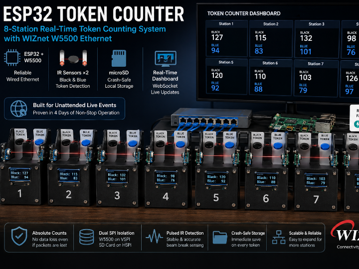
ESP32 + W5500 Token Counter: A Reliable 8-Station Event System
Project Overview
The ESP32 Token Counter is a distributed installation designed to count two types of physical tokens across eight independent stations.
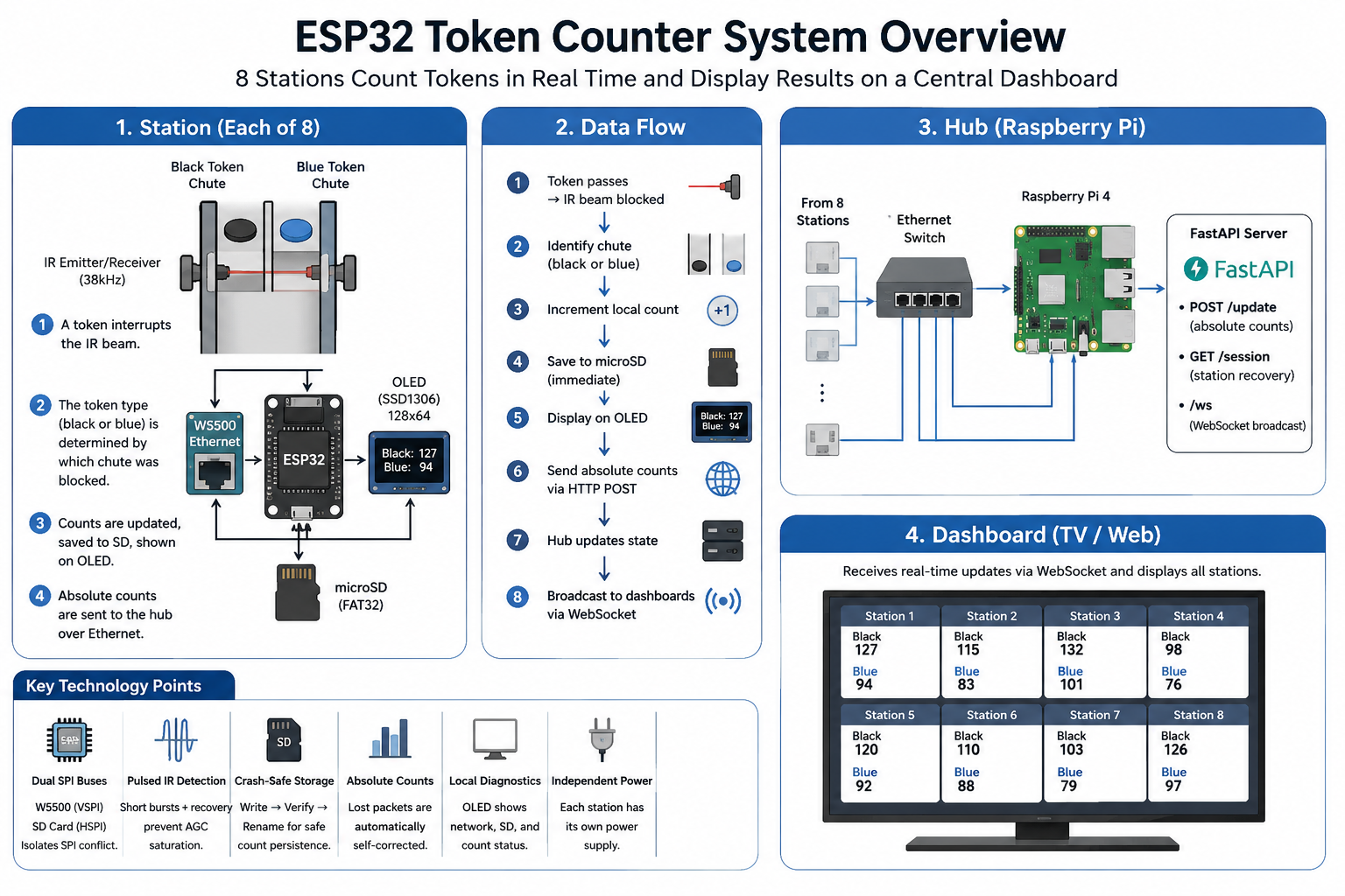
Each station combines an ESP32, two infrared sensors, an SSD1306 OLED, a microSD card, and a WIZnet W5500 Ethernet module. When a black or blue token passes through its chute, the station updates the local count, saves it to the SD card, and sends the latest value to a Raspberry Pi hub.
The Raspberry Pi runs a FastAPI server and broadcasts the combined station data to a browser dashboard using WebSockets. A connected TV can therefore display the results from all eight stations in real time.
The repository is a sanitized reference version of a system that operated unattended for four days at a live event. Client branding, production addresses, and administrative functions were removed, but the core firmware and reliability-related design decisions remain.
System Architecture
Each station includes:
ESP32 development board
WIZnet W5500 Ethernet module
Two 38 kHz IR emitter and receiver pairs
SSD1306 128 × 64 OLED
microSD card and adapter
Individual USB power supply
All eight stations connect through an Ethernet switch to a Raspberry Pi 4.
The hub provides three main interfaces:
POST /update receives absolute counts.
GET /session returns the stored count for a station.
/ws broadcasts updates to connected dashboards.
Data Flow
A token interrupts an IR beam.
The ESP32 identifies the black or blue chute.
The local counter is incremented.
Both counts are saved to the SD card.
The OLED displays the new values.
The ESP32 sends the absolute counts over Ethernet.
The Raspberry Pi updates the shared state.
WebSocket clients receive the latest dashboard data.
Why W5500 Ethernet Was Used
Although the ESP32 supports Wi-Fi, crowded event venues can be difficult RF environments. Smartphones, access points, Bluetooth devices, and other wireless equipment can reduce connection reliability once visitors enter the venue.
Since each station already required a power cable, the developer decided that adding an Ethernet cable was a reasonable trade-off for a more stable network.
The W5500 gives the ESP32 a dedicated hardwired TCP/IP connection and allows the application to use standard HTTP communication without depending on local RF conditions.
For a four-day unattended installation, predictable connectivity was more important than minimizing cable count.
Key Challenge 1: W5500 and SD Card SPI Conflict
The most instructive hardware problem involved the W5500 and microSD adapter sharing an SPI bus.
Normally, inactive SPI devices should release the MISO line. However, the low-cost level-shifting SD adapter did not properly place MISO in a high-impedance state when deselected. Its output buffer continued driving the line, causing the W5500 to appear missing.
Disconnecting only the SD adapter's MISO wire restored W5500 communication, confirming that the Ethernet module itself was not defective.
Dual-SPI Solution
The ESP32's two hardware SPI controllers were used to isolate the devices:
| Device | SPI Bus | SCK | MISO | MOSI | CS |
|---|---|---|---|---|---|
| W5500 | VSPI | GPIO 18 | GPIO 19 | GPIO 23 | GPIO 5 |
| microSD | HSPI | GPIO 14 | GPIO 27 | GPIO 13 | GPIO 15 |
The SD interface is created as a separate SPIClass(HSPI) instance and passed to SD.begin().
This physically isolates the W5500 from the non-compliant SD adapter. The project also recommends keeping SPI wiring short and avoiding GPIO 12 for SD MISO because it is an ESP32 boot-strapping pin.
This is a useful troubleshooting lesson: when a W5500 disappears after another SPI device is added, the cause may be incorrect MISO behavior rather than the W5500 or its software library.
Key Challenge 2: Pulsed IR Detection
The token chutes use 38 kHz infrared receivers originally designed for modulated remote-control signals.
A continuous 38 kHz carrier did not work reliably because the receiver's automatic gain control eventually suppressed the constant signal. After a short period, the beam appeared permanently absent.
The final firmware therefore uses short IR bursts followed by recovery intervals:
38 kHz carrier
600 µs transmission burst
Receiver sampling during the burst
1,400 µs recovery interval
Additional loop pacing and debounce delays
The firmware counts only the transition from an intact beam to a broken beam. A token remaining in the chute does not create repeated counts.
At startup, both sensors must also report a stable clear condition for multiple readings before counting is enabled. This prevents startup transients from being mistaken for tokens.
Key Challenge 3: Crash-Safe Local Storage
Every detected token is immediately written to the microSD card. The station does not wait for a batch or periodic save interval.
The count file uses a simple format:
black,blue
Instead of writing directly to the active file, the firmware:
Writes the new values to a temporary file.
Flushes and closes the file.
Verifies that the file is not empty.
Removes the previous count file.
Renames the temporary file.
If power is lost during the operation, the boot routine can recover the remaining temporary file.
This approach reduces the possibility of accepting a partially written count. Immediate SD writes increase memory wear, but for a temporary event installation, preserving every token was the higher priority.
Absolute Counts Improve Network Reliability
The stations send complete cumulative totals rather than messages such as “add one token.”
Example:
{"station_id":1,"black":127,"blue":94}
This makes the communication naturally tolerant of lost packets.
If an update is missed, the next successful transmission contains the latest total and automatically corrects the hub. Sending the same value again also does not create a duplicate count.
The firmware limits the HTTP response wait time so that a disconnected or slow hub cannot block sensor polling for an extended period.
OLED and Local Diagnostics
The OLED displays:
Station ID
Ethernet status
SD card status
Black token count
Blue token count
This allows installers to identify common faults without connecting a serial terminal.
For example, a station can continue counting and saving locally even when the network is unavailable. Once the connection returns, its latest absolute values can be reported to the hub.
Raspberry Pi Hub and Dashboard
The Raspberry Pi software is intentionally lightweight.
FastAPI stores the latest count for each station and broadcasts the complete state to connected browsers whenever an update arrives. The browser dashboard displays each station as a card containing its black and blue totals.
The system operates entirely on the local network:
No cloud service is required.
Multiple displays can connect simultaneously.
Dashboard values update without page refresh.
The FastAPI server can start automatically through systemd.
Important Recovery Limitation
The intended startup recovery order is:
Restore from the hub.
Otherwise restore from SD.
Otherwise start from zero.
However, the reference code contains an important edge case.
The FastAPI hub stores its state only in RAM. After a Raspberry Pi or server restart, an unknown station receives a valid response containing zero counts. The ESP32 may treat this as authoritative and overwrite a valid SD count with zero.
A safer design would allow the hub to distinguish between:
A valid stored count of zero
No stored record for the station
For example, the hub could return HTTP 404 or:
{"found":false}
When no hub record exists, the ESP32 should restore from SD and upload the recovered value back to the server.
For production use, the hub should also save state to SQLite, Redis, or another persistent storage system.
SD Card Compatibility Issue
The developer ordered 16 GB SD cards but received 64 GB cards instead. The larger cards were supplied with exFAT formatting, which the project's ESP32 SD.h configuration could not mount.
The failure initially appeared to be a firmware problem but was actually caused by a supplier substitution and filesystem mismatch.
The recommended configuration is:
32 GB or smaller microSD card
FAT32 filesystem
Short SPI wiring
Dedicated HSPI connection
Hardware Summary
| Component | Function |
|---|---|
| ESP32 | Sensor processing and system control |
| W5500 | Wired TCP/IP communication |
| Two IR sensor pairs | Detect black and blue tokens |
| SSD1306 OLED | Display counts and status |
| microSD card | Preserve counts during failures |
| Ethernet switch | Connect all stations and the hub |
| Raspberry Pi 4 | Run FastAPI and the dashboard |
| TV or monitor | Display the combined result |
Each station uses an independent power supply so that one power failure does not disable the entire installation.
Possible Applications
The same architecture can be adapted for:
Exhibition voting systems
Donation token counters
Recycling participation displays
Museum interaction systems
School or event scoreboards
Retail campaign counters
Multi-lane object counting
Factory part counters
The IR sensors could also be replaced with push buttons, RFID readers, coin acceptors, magnetic sensors, or industrial proximity sensors.
Why This Is a Useful W5500 Reference
This project demonstrates how W5500 Ethernet can support a practical reliability strategy rather than simply provide network connectivity.
Key design lessons include:
Wired Ethernet avoids congested RF environments.
Absolute values recover automatically from lost packets.
Local SD storage allows operation during network failure.
Dual SPI buses isolate the W5500 from problematic peripherals.
Independent station power limits the impact of hardware failures.
A local Raspberry Pi hub removes dependence on cloud services.
The SPI conflict is particularly valuable because it shows how a non-compliant SD adapter can make a properly functioning W5500 appear defective.
Potential Applications
Although originally developed for a live interactive event, the architecture can be applied to many other applications that require reliable collection of physical user interactions.
Typical use cases include:
Interactive Exhibitions & Museums – Visitor voting, quizzes, and participation-based displays.
Events & Brand Campaigns – Product preference voting, promotional activities, and audience engagement.
Retail & Customer Feedback – In-store satisfaction surveys and product popularity tracking.
Education & STEM Learning – Classroom voting systems and interactive science exhibits.
Donation & Public Campaigns – Charity fundraising events and community participation activities.
Industrial Counting Systems – Counting parts, products, or production events using optical sensors instead of manual recording.
The project demonstrates how a simple combination of ESP32, W5500 Ethernet, and optical sensors can build a reliable distributed data collection system. While this implementation counts physical tokens, the same architecture can easily be adapted to buttons, RFID readers, barcode scanners, proximity sensors, or other industrial sensors that generate countable events.