
DiSoCon
DiSoCon
1) What this project does
DiSoCon2 is designed to manage a domestic solar hot water system with multiple storage tanks. According to the README, it reads four PT1000 sensors for the solar collector, primary tank, secondary tank, and return line, calculates temperature differentials, and drives pumps and 3-way valves accordingly, while exposing live data through Ethernet and MQTT for Home Assistant integration.
2) The most important architectural idea

The strongest design point is the separation of responsibilities.
- ESP32-S3 handles the main control logic, networking, MQTT, display/UI, and ESPHome integration.
- ATmega32U4 handles the analog front-end and PT1000 measurement.
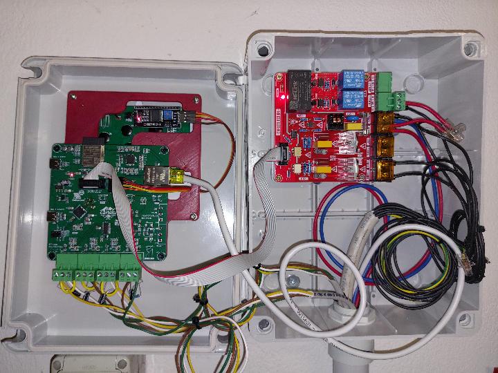
- The hardware is split into a control board and a power board, connected through a 10-pin ribbon cable. The README explicitly shows this two-board architecture, with the control board containing the ATmega32U4, ESP32-S3, W5500, MCP6004, MAX13487, and ADS1115, and the power board hosting the mains supply and actuator-driving section.
This is a very sensible choice for a real thermal-control product because it separates low-level analog measurement and digital control from the high-voltage pump and valve driving section, which helps with noise isolation and maintainability. That is an engineering-oriented architecture, not just a hobby prototype.
3) Software structure
The software is split into two layers:
- ESPHome YAML on the ESP32-S3
- Arduino firmware on the ATmega32U4
The ESPHome side is modular. main.yaml includes many separate packages such as ethernet.yaml, mqtt.yaml, sensor.yaml, switch.yaml, binary_sensor.yaml, interval.yaml, and uart.yaml, which makes the project easier to maintain than one huge monolithic YAML file.
On the ATmega side, the firmware performs the PT1000 readout and then periodically sends channel values over Serial1. The code shows a 15,000 ms read interval, and the transmitted format is an ASCII line protocol such as <index>x<value>\n.
One interesting detail is that the README presents the design as having RS-485 field bus capability, and the ATmega code still contains RS-485-oriented comments and a RS485_DE_PIN, but the ESPHome side currently defines a direct UART link on the ESP32 using rx_pin: GPIO21, tx_pin: GPIO4, and baud_rate: 9600. So the current published implementation looks more like ATmega-to-ESP32 internal UART transport, while RS-485 appears to be part of the broader hardware capability or an earlier design path. That is a reasonable inference from the published code and documentation, but it is worth noting as a documentation/code mismatch.
4) Control logic maturity
This project is more advanced than a basic “if delta-T is high, turn pump on” controller.
The ESPHome logic includes:
- watchdog handling for UART data loss,
- publishing
NANwhen no UART data arrives for 30 seconds, - automatic tank switching logic,
- PWM control logic for the solar pump,
- manual override paths,
- and thermal power estimation.
A particularly good example is the tank switching logic in binary_sensor.yaml. The state named Uso Serbatoio checks the temperatures of the two tanks and switches the active storage path when Tank 2 reaches its setpoint, then returns when Tank 1 is saturated or when Tank 2 cools sufficiently below its threshold. That is much more practical than a fixed single-tank controller and shows the project was built around a real operating use case.
The UART watchdog is also well thought out. If no data is received from the ATmega for more than 30 seconds, the ESPHome logic publishes NAN for the temperature states, which is a safer behavior than silently holding stale values.
