



W5500-Based ESP32-S3 micro-ROS Node Suite for a Distributed Rover Control System
Five ESP32-S3 nodes connect ROS 2 to rover motors, BMS telemetry, and status LEDs through W5500 Ethernet and micro-ROS.
Project Overview
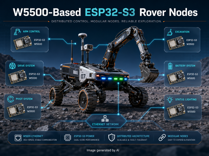
2026_ESP_Nodes is a collection of embedded firmware projects developed for the Swinburne Rover Team’s 2026 rover system. The repository separates the rover electronics into five ESP32-S3 nodes:
Arm_ESP
BMS_ESP
Excavation_ESP
Pivot_ESP
Status_ESP
Each directory is an independent PlatformIO project rather than a single multi-target firmware build. The nodes share a common foundation consisting of the Arduino framework, micro_ros_platformio, ROS 2 Jazzy configuration, custom micro-ROS transport, and the Arduino Ethernet library. The repository README also states that nodes using motor-control libraries require separate imports from the team’s SRT_CAN_MOTOR project.
Project Type
Distributed rover subsystem firmware
ROS 2 edge control and I/O nodes
ESP32-S3 embedded application suite
Ethernet-to-CAN/UART/GPIO gateway architecture
PlatformIO and Arduino-based prototype firmware
Node Composition
Arm_ESP
Arm_ESP receives ROS 2 commands for arm joints, gripper operation, stop, homing, restart, and emergency-stop behavior. It converts these commands into CAN messages for three ODrive motor controllers and two CANopen-compatible motor controllers. The node also defines an Arm_Diagnostics publisher for status reporting.
Main interfaces:
W5500 Ethernet over SPI
micro-ROS subscribers and diagnostics publisher
ESP32 TWAI controller at 500 kbit/s
Three ODrive CAN node IDs
Two CANopen motor node IDs
Pivot_ESP
Pivot_ESP handles the rover’s drive and pivot actuator commands. Its ROS 2 interface includes drive, rotation, stop, home, restart, and kill-switch topics, together with a diagnostics publisher. The source configures four ODrive controllers and four CANopen motor controllers.
A 300 ms communication watchdog is implemented for the GIM motor path. Loss of expected motor communication triggers a stop condition, providing a local protection mechanism independent of normal ROS command flow.
Excavation_ESP
Excavation_ESP is a smaller actuator node dedicated to the excavation fork. It subscribes to the Excavation_Fork topic and controls a CANopen motor through the ESP32 TWAI interface. The source includes motion scaling, gear-ratio configuration, and position bounds for the mechanism.
BMS_ESP
BMS_ESP operates as a gateway between ROS 2 and a JK/Jikong battery management system connected through Serial2. Battery measurements, warnings, connection state, and total voltage are assembled into JSON and published through the BMS_Diagnostics topic.
The node also accepts commands for charge and discharge MOSFET control, battery reset, and emergency battery disconnection. When the kill-switch message is active, the firmware requests both charge and discharge paths to be disabled.
Status_ESP
Status_ESP uses an addressable NeoPixel LED as a rover status indicator. Its active ROS 2 subscriber receives the KillSwitch state, while the LED state machine represents initialization, connection errors, rover errors, manual mode, and other operating conditions.
Several planned topics, including mechanical failure, homing completion, automatic mode, and manual mode, remain commented out. The current implementation therefore provides only part of the status model represented by the source-level state machine.
System Architecture
                    ROS 2 Jazzy Host
                           │
                    micro-ROS Agent
                           │
                 UDP over Wired Ethernet
                           │
              ┌──────── Ethernet Switch ────────┐
              │            │          │          │
         W5500 + ESP32  W5500 + ESP32 ...  W5500 + ESP32
              │
       micro-ROS RCL/RCLC Node
              │
     ┌────────┼───────────┐
     │        │           │
 TWAI/CAN   UART       GPIO/NeoPixel
     │        │           │
 ODrive /   JK BMS     Status Indicator
 CANopen
 Motors
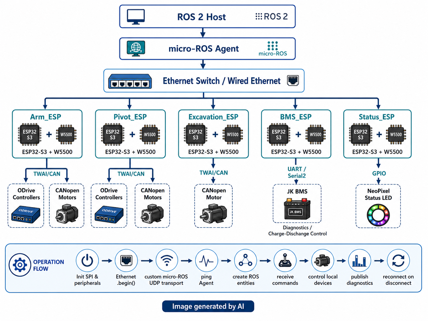
All five applications use the W5500 as the ESP32-S3’s wired network interface. The W5500 is connected through SPI, while local subsystem communication is handled separately through CAN, UART, or GPIO depending on the node.
Operation and Data Flow
Hardware initialization
The ESP32-S3 initializes its serial interface, SPI bus, W5500 chip-select configuration, and subsystem-specific peripherals.
Ethernet configuration
The firmware calls Ethernet.begin() with a fixed MAC address, static IP address, DNS server, and gateway.
micro-ROS custom transport registrationrmw_uros_set_custom_transport() registers callback functions based on EthernetUDP. These callbacks open a UDP endpoint, transmit packets through beginPacket() and endPacket(), and receive incoming micro-ROS data.
Agent discovery and connection
The node periodically calls rmw_uros_ping_agent(). When the agent responds, the firmware creates its RCL allocator, support object, node, publishers, subscribers, and executor.
ROS command processingrclc_executor_spin_some() dispatches incoming messages to node-specific callbacks.
Local device control
The callback converts the ROS message into CAN commands, BMS UART commands, or LED state changes.
Diagnostics and recovery
Diagnostics are published where implemented. If the agent stops responding, the node destroys its micro-ROS entities and returns to the agent discovery state.
WIZnet Product Assessment
WIZnet Product
W5500 Ethernet Controller
WIZnet Product Role
The W5500 provides the SPI-based Ethernet interface for every ESP32-S3 node. It carries the UDP communication path between each micro-ROS client and the external micro-ROS Agent.
micro-ROS RCL/RCLC
        │
Custom transport callbacks
        │
EthernetUDP
        │
Arduino Ethernet library
        │
W5500 hardware socket
        │
10/100 Ethernet
The application code does not directly manipulate W5500 socket registers. Instead, it uses the Arduino Ethernet library and EthernetUDP, which ultimately operate the W5500 hardware socket engine. The inspected transport does not use ESP-IDF esp_eth, esp_netif, or a software lwIP socket path.
TOE Usage
TOE Use: Confirmed
The W5500 integrates a hardwired TCP/IP stack, Ethernet MAC, Ethernet PHY, internal packet memory, and eight hardware sockets. It supports UDP processing inside the controller rather than requiring the ESP32-S3 application processor to execute the complete network stack.
The project accesses this capability indirectly:
Direct W5500 socket-register control: Not used in the inspected application transport
Arduino Ethernet library: Used
EthernetUDP: Used
ESP-IDF esp_eth / esp_netif / lwIP: Not used in the inspected node implementation
MACRAW mode: Not configured in the inspected transport
Actual micro-ROS transport protocol: UDP
TOE classification: W5500 hardware UDP socket processing through a library-mediated interface
This is a TOE-based implementation even though the firmware does not directly call low-level W5500 register functions.
Hybrid Network Assessment
Hybrid Network: No
The inspected nodes use W5500 Ethernet as their ROS 2 network connection. No Wi-Fi initialization, wireless transport, or simultaneous Ethernet/Wi-Fi routing path is implemented in the five node applications.
CAN, UART, and GPIO coexist with Ethernet, but these are local device interfaces rather than a second wireless network. The project therefore does not meet the Hybrid Network criterion of using wired and wireless networking in the same operating system.
Strengths
1. Clear subsystem separation
Arm, pivot, excavation, battery, and status functions are assigned to independent controllers. A fault or firmware change in one subsystem can be isolated from the remaining nodes more easily than in a single-controller design.
2. Consistent ROS 2 communication model
The nodes share a common micro-ROS connection state machine and custom Ethernet transport. This reduces architectural variation between subsystems and makes host-side integration more consistent.
3. Effective use of the W5500 TOE
The W5500 provides a dedicated wired communication interface and performs UDP/IP processing through its hardware socket engine. This reduces the amount of network-stack work assigned to the ESP32-S3 while leaving its processing resources available for CAN, motor-control, BMS, and safety logic.
4. Multiple embedded interface bridges
The project demonstrates several practical ROS 2 gateway patterns:
ROS 2 to ODrive CAN
ROS 2 to CANopen motor control
ROS 2 to JK BMS UART communication
ROS 2 to an addressable status indicator
5. Connection recovery and local protection
The nodes monitor the micro-ROS Agent and recreate their entities after a disconnection. Kill-switch callbacks, stop commands, BMS MOSFET shutdown, and the pivot communication watchdog provide local fault-response mechanisms.
Limitations
1. Minimal repository documentation
The root README only identifies the project as the 2026 ESP node collection and briefly mentions the external motor library requirement. Wiring diagrams, node deployment instructions, ROS 2 launch configuration, topic contracts, and commissioning procedures are not provided.
2. Fixed network configuration
MAC addresses, static IP addresses, gateway settings, and the micro-ROS Agent endpoint are embedded in the source. Changing the rover network requires recompilation unless a separate configuration mechanism is added.
3. Repeated transport and connection code
Each PlatformIO project contains a similar Ethernet transport and micro-ROS connection implementation. This structure simplifies independent builds but increases the risk of behavioral differences when fixes are applied to only some nodes.
4. Incomplete status functionality
Several Status_ESP inputs and LED states are present only as commented or future-season code. The implemented status node does not yet expose the complete operating-state model suggested by the source.
5. External motor-library dependency
The motor-control nodes depend on libraries that must be imported separately from another repository. A clean checkout is therefore not necessarily sufficient to reproduce all firmware builds without additional manual setup.
6. Validation evidence
Repository-level results for Ethernet latency, packet-loss behavior, CAN bus saturation, emergency-stop response time, long-duration operation, or hardware-in-the-loop testing are not documented.
Application Value
This project provides a practical reference for distributing ROS 2 control across multiple embedded nodes in a mobile robot. Its strongest reusable elements are:
W5500-based micro-ROS UDP transport on ESP32-S3
Separation of high-level ROS 2 control from local actuator interfaces
Ethernet-to-CAN gateway implementation
Ethernet-to-BMS UART gateway implementation
Agent monitoring and automatic reconnection
Local safety handling outside the central ROS 2 computer
The architecture can be adapted to competition rovers, autonomous mobile robots, industrial mobile platforms, agricultural machines, and other systems that require multiple embedded controllers connected to a central ROS 2 host.
The repository is more suitable as a code-level subsystem reference than as a ready-to-deploy firmware package because network provisioning, hardware integration, dependency installation, and validation procedures require additional project-specific work.
Final Assessment
2026_ESP_Nodes presents a coherent distributed control architecture in which W5500-equipped ESP32-S3 nodes connect ROS 2 to motors, battery electronics, and status hardware.
Its primary technical value lies in the combination of:
W5500 hardware TCP/IP offload
micro-ROS over UDP
ESP32 TWAI/CAN motor control
UART-based battery telemetry
Subsystem-level recovery and safety logic
The implementation contains substantial subsystem code, but repository documentation and reproducible deployment support remain limited.
Author Information
Repository owner: SwinRoverTeam
Organization: Swinburne Rover Team
Team profile: A student-led engineering team associated with Swinburne University of Technology that develops rover systems for simulated lunar environments and rover competitions.
Individual subsystem authors: Repository README does not specify individual ownership.
W5500 기반 ESP32-S3 멀티 서브시스템 로버 micro-ROS 노드
프로젝트 개요
2026_ESP_Nodes는 Swinburne Rover Team의 2026년 로버 시스템에 사용되는 ESP32-S3 펌웨어 모음이다. 하나의 MCU가 전체 장치를 제어하지 않고 다음 5개 노드가 기능을 분담한다.
Arm_ESP: 로봇 팔과 그리퍼 제어
Pivot_ESP: 주행 및 피벗 구동계 제어
Excavation_ESP: 굴착 포크 제어
BMS_ESP: 배터리 상태 수집과 충·방전 제어
Status_ESP: 로버 상태 LED 표시
각 노드는 독립된 PlatformIO 프로젝트이며, Arduino framework, ESP32-S3, micro_ros_platformio, ROS 2 Jazzy 설정, Arduino Ethernet library, 사용자 정의 micro-ROS 전송 계층을 공통으로 사용한다. 모터 제어 노드는 별도의 SRT_CAN_MOTOR 라이브러리를 개별적으로 가져와야 한다.
프로젝트 유형
로버용 분산 임베디드 제어 펌웨어
ROS 2 엣지 제어 및 I/O 노드
ESP32-S3 기반 멀티 노드 시스템
Ethernet-CAN/UART/GPIO 게이트웨이
PlatformIO·Arduino 기반 프로토타입
노드별 구성
Arm_ESP
Arm_ESP는 관절, 그리퍼, 정지, 원점 복귀, 재시작, 비상 정지와 관련된 ROS 2 명령을 수신한다. 수신한 명령은 ESP32의 TWAI 인터페이스를 통해 CAN 프레임으로 변환되며, 세 개의 ODrive와 두 개의 CANopen 계열 모터 컨트롤러에 전달된다.
상태 보고를 위한 Arm_Diagnostics publisher도 정의되어 있다.
주요 인터페이스:
SPI 기반 W5500 Ethernet
micro-ROS subscriber 및 diagnostics publisher
500 kbit/s ESP32 TWAI/CAN
ODrive 모터 컨트롤러 3개
CANopen 모터 컨트롤러 2개
Pivot_ESP
Pivot_ESP는 로버의 주행 및 피벗 구동계를 담당한다. ROS 2 인터페이스에는 주행, 회전, 정지, 원점 복귀, 재시작, Kill Switch 명령과 진단 publisher가 포함된다.
코드에는 네 개의 ODrive와 네 개의 CANopen 모터 컨트롤러가 구성되어 있다. GIM 모터 통신을 감시하는 300 ms watchdog도 포함되어 있으며, 지정 시간 안에 통신이 확인되지 않으면 모터 정지 상태로 전환한다.
Excavation_ESP
Excavation_ESP는 굴착 포크 구동에 특화된 단일 액추에이터 노드이다. Excavation_Fork 토픽에서 명령을 수신하고, TWAI 인터페이스를 통해 CANopen 모터를 제어한다.
소스에는 감속비, 조이스틱 입력 배율, 이동 범위 제한이 포함되어 있어 굴착 장치의 물리적 조건을 펌웨어 수준에서 반영한다.
BMS_ESP
BMS_ESP는 ROS 2와 JK/Jikong BMS 사이의 게이트웨이로 동작한다. BMS는 ESP32-S3의 Serial2에 연결되며, 셀과 배터리 상태, 경고 정보, 연결 상태, 전체 전압 등이 JSON 문자열로 구성되어 BMS_Diagnostics 토픽으로 전송된다.
ROS 2에서는 충전 및 방전 MOSFET 상태 변경, BMS 재시작, 비상 배터리 차단 명령을 전달할 수 있다. Kill Switch가 활성화되면 충전과 방전 경로를 모두 비활성화하도록 요청한다.
Status_ESP
Status_ESP는 주소 지정형 NeoPixel LED로 로버 상태를 표현한다. 연결 초기화, ROS 통신 오류, 로버 오류, 수동 운전 등의 상태가 LED 상태 머신에 정의되어 있다.
현재 활성화된 ROS 2 입력은 KillSwitch이며, 기계적 고장, 원점 복귀 완료, 자동 모드, 수동 모드와 관련된 subscriber는 주석 처리되어 있다. 따라서 소스에 설계된 전체 상태 표시 기능 가운데 일부만 실제 동작 코드에 연결되어 있다.
시스템 구조
                      ROS 2 Jazzy 호스트
                              │
                       micro-ROS Agent
                              │
                       UDP / Ethernet
                              │
                    ┌──── Ethernet Switch ────┐
                    │            │             │
              W5500 + ESP32  W5500 + ESP32  W5500 + ESP32
                    │
              micro-ROS RCL/RCLC
                    │
          ┌─────────┼──────────┐
          │         │          │
       TWAI/CAN    UART     GPIO/NeoPixel
          │         │          │
       ODrive·    JK BMS     상태 표시 LED
       CANopen
       모터
모든 노드에서 W5500은 ESP32-S3의 유선 네트워크 인터페이스로 사용된다. W5500과 ESP32-S3는 SPI로 연결되며, 각 노드의 로컬 하드웨어는 CAN, UART 또는 GPIO를 통해 제어된다.
동작 및 데이터 흐름
하드웨어 초기화
ESP32-S3가 Serial, SPI, W5500 chip-select 설정과 노드별 주변 장치를 초기화한다.
Ethernet 설정Ethernet.begin()에 MAC 주소, 고정 IP 주소, DNS, gateway 정보를 전달한다.
micro-ROS 사용자 정의 전송 계층 등록rmw_uros_set_custom_transport()를 통해 EthernetUDP 기반 open, close, read, write callback을 micro-ROS에 등록한다.
micro-ROS Agent 탐색rmw_uros_ping_agent()를 반복 호출하여 Agent 응답 여부를 확인한다.
ROS 2 entity 생성
Agent 연결이 확인되면 RCL allocator, support, node, publisher, subscriber, executor를 생성한다.
명령 처리rclc_executor_spin_some()이 수신 메시지를 각 callback에 전달한다.
로컬 장치 제어
callback이 메시지를 CAN 명령, BMS UART 명령 또는 LED 상태로 변환한다.
연결 복구
Agent 응답이 중단되면 기존 micro-ROS entity를 제거하고 다시 Agent 탐색 상태로 돌아간다.
WIZnet 제품 사용 여부
사용 제품
W5500 Ethernet Controller
WIZnet Product Role
W5500은 5개 ESP32-S3 노드 모두에서 SPI 기반 유선 Ethernet 인터페이스로 사용된다. 각 micro-ROS client와 외부 micro-ROS Agent 사이의 UDP 통신 경로를 담당한다.
micro-ROS RCL/RCLC
        │
Custom Transport Callback
        │
EthernetUDP
        │
Arduino Ethernet Library
        │
W5500 Hardware Socket
        │
10/100 Ethernet
애플리케이션은 W5500 socket register를 직접 제어하지 않는다. 사용자 정의 micro-ROS 전송 코드는 EthernetUDP와 Arduino Ethernet library를 이용하며, 이 라이브러리 아래에서 W5500의 하드웨어 socket이 동작한다.
ESP-IDF의 esp_eth, esp_netif 또는 일반적인 소프트웨어 lwIP socket 계층을 사용하는 구조는 확인되지 않는다.
TOE 사용 여부
TOE 사용: 확인됨
W5500은 TCP/IP stack, Ethernet MAC, PHY, 패킷 메모리와 8개의 하드웨어 socket을 내장한 Hardwired TCP/IP Ethernet Controller이다. 이 프로젝트에서 사용되는 UDP/IP 처리는 ESP32-S3의 소프트웨어 네트워크 스택이 아니라 W5500의 하드웨어 socket을 통해 수행된다.
세부 경로는 다음과 같다.
W5500 socket register 직접 제어: 확인되지 않음
Arduino Ethernet library 경유: 사용
EthernetUDP 경유: 사용
ESP-IDF esp_eth / esp_netif / lwIP socket 경유: 확인되지 않음
MACRAW 모드: 사용하지 않음
micro-ROS 전송 프로토콜: UDP
TOE 판단: Arduino Ethernet library를 경유한 W5500 하드웨어 UDP socket 사용
저수준 socket register를 애플리케이션이 직접 조작하지 않더라도, 실제 UDP/IP 처리가 W5500 내부의 하드웨어 socket에서 수행되므로 TOE 사용에 해당한다.
Hybrid Network 여부
Hybrid Network: 해당 없음
확인된 5개 노드는 ROS 2 네트워크 연결에 W5500 Ethernet만 사용한다. Wi-Fi 초기화, 무선 전송 계층 또는 Ethernet과 Wi-Fi를 동시에 운용하는 경로는 코드에서 확인되지 않는다.
Ethernet과 CAN, UART가 함께 사용되지만 CAN과 UART는 로컬 장치용 인터페이스이며 무선 네트워크가 아니다. 따라서 유선과 무선을 하나의 시스템에서 병행한다는 Hybrid Network 기준에는 해당하지 않는다.
장점
1. 명확한 서브시스템 분리
로봇 팔, 구동계, 굴착 장치, 배터리, 상태 표시 기능을 독립 MCU로 분리했다. 특정 노드의 장애나 펌웨어 변경이 전체 시스템에 직접 확산되는 범위를 줄일 수 있다.
2. 일관된 ROS 2 연결 구조
노드들이 공통 micro-ROS 연결 상태 머신과 W5500 전송 구조를 사용한다. 각 서브시스템의 ROS 2 연결 방법이 통일되어 호스트 측 구성과 문제 분석이 단순해진다.
3. W5500 TOE의 실질적 활용
UDP/IP 처리를 W5500 하드웨어 socket에 맡기고, ESP32-S3는 CAN, 모터 제어, BMS 처리와 안전 로직에 집중한다. 단순히 Ethernet PHY만 추가한 구조가 아니라 W5500의 Hardwired TCP/IP 기능을 실제 통신 경로에서 사용한다.
4. 다양한 ROS 2 임베디드 게이트웨이 구현
하나의 저장소에서 다음 인터페이스 변환 사례를 확인할 수 있다.
ROS 2-CAN-ODrive
ROS 2-CANopen 모터
ROS 2-UART-JK BMS
ROS 2-NeoPixel 상태 표시
5. 연결 복구와 로컬 안전 처리
micro-ROS Agent 연결 상태를 주기적으로 감시하고, 연결이 끊어지면 entity를 제거한 뒤 재접속한다. Kill Switch, 모터 정지, BMS MOSFET 차단, Pivot 통신 watchdog 등 일부 위험 대응은 중앙 ROS 2 호스트와 별도로 노드 내부에서도 처리된다.
한계
1. 저장소 문서 부족
루트 README에는 프로젝트 명칭과 외부 모터 라이브러리 의존성만 간략히 기록되어 있다. 배선도, 전체 네트워크 구성, ROS 2 Agent 실행 방법, 토픽 명세, 빌드 및 배포 순서, 초기 시운전 절차는 제공되지 않는다.
2. 소스에 고정된 네트워크 설정
MAC 주소, 고정 IP, gateway, micro-ROS Agent 주소와 포트가 코드에 직접 정의되어 있다. 네트워크 구성을 변경하려면 별도의 설정 저장 구조를 추가하거나 펌웨어를 다시 빌드해야 한다.
3. 노드별 중복 코드
각 PlatformIO 프로젝트가 Ethernet transport와 micro-ROS 연결 관리 코드를 개별적으로 보유한다. 노드를 독립적으로 빌드하기에는 편리하지만, 공통 오류를 수정할 때 모든 프로젝트에 같은 변경을 반영해야 한다.
4. 미완성 상태 표시 기능
Status_ESP에 다수의 상태와 subscriber가 설계되어 있으나 일부는 주석 처리되어 있다. 현재 구현은 소스에 정의된 전체 로버 상태 모델을 완전히 반영하지 않는다.
5. 외부 모터 라이브러리 의존성
모터 제어 노드는 별도 저장소의 라이브러리를 수동으로 가져와야 한다. 현재 저장소만 복제해서는 모든 노드를 동일한 상태로 빌드하지 못할 가능성이 있다.
6. 검증 자료
다음 항목에 대한 저장소 내 시험 결과는 확인되지 않는다.
Ethernet 지연 시간과 jitter
패킷 손실 시 동작
CAN bus 부하 및 충돌 조건
비상 정지 응답 시간
장시간 연속 운전
Hardware-in-the-loop 시험
실제 로버 통합 시험 절차
적용 가치
이 프로젝트는 중앙 ROS 2 컴퓨터와 여러 임베디드 제어기를 유선 Ethernet으로 연결하는 로봇 시스템의 실용적인 코드 사례를 제공한다.
재사용 가치가 높은 부분은 다음과 같다.
ESP32-S3와 W5500을 이용한 micro-ROS UDP 전송
ROS 2 명령과 로컬 모터 제어의 분리
Ethernet-CAN 제어 게이트웨이
Ethernet-UART BMS 게이트웨이
micro-ROS Agent 감시 및 자동 재연결
중앙 컴퓨터 연결 상태와 별도로 실행되는 로컬 안전 처리
동일한 구조는 경기용 로버, 자율주행 이동 로봇, 산업용 이동 장비, 농업 로봇처럼 여러 제어 노드를 중앙 ROS 2 시스템에 연결해야 하는 장비에 적용할 수 있다.
다만 네트워크 설정, 하드웨어 배선, 외부 의존성, 설치 절차와 검증 자료가 충분히 패키징되어 있지 않아 완제품 펌웨어보다는 서브시스템 구현 참고 자료에 가깝다.
최종 평가
2026_ESP_Nodes는 W5500이 장착된 ESP32-S3 노드를 이용해 ROS 2와 모터, 배터리 장치, 상태 표시 장치를 연결하는 분산 로버 제어 시스템이다.
주요 기술 구성은 다음과 같다.
W5500 Hardwired TCP/IP Offload
UDP 기반 micro-ROS
ESP32 TWAI/CAN 모터 제어
UART 기반 BMS 상태 수집 및 제어
노드별 연결 복구와 안전 로직
서브시스템 구현 코드는 구체적이며 W5500 TOE가 실제 ROS 2 통신 경로에 사용된다. 반면 문서화, 공통 설정 관리, 외부 의존성 통합과 시험 결과는 보완이 필요하다.
저자 정보
저장소 소유자: SwinRoverTeam
조직: Swinburne Rover Team
조직 성격: Swinburne University of Technology를 기반으로 모의 달 탐사 환경과 로버 대회를 위한 시스템을 개발하는 학생 주도 엔지니어링 팀
서브시스템별 개인 저자: 저장소 README 내 명시 없음
-
2026_ESP_Nodes
