
Four-Electrode Bioelectrical Impedance–Based Pericardial Puncture Assistance System
A research system using four-electrode bioimpedance measurement to assist pericardial puncture and stream data via Ethernet.
Overview
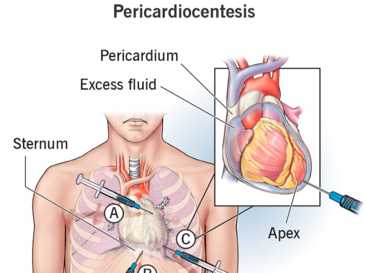
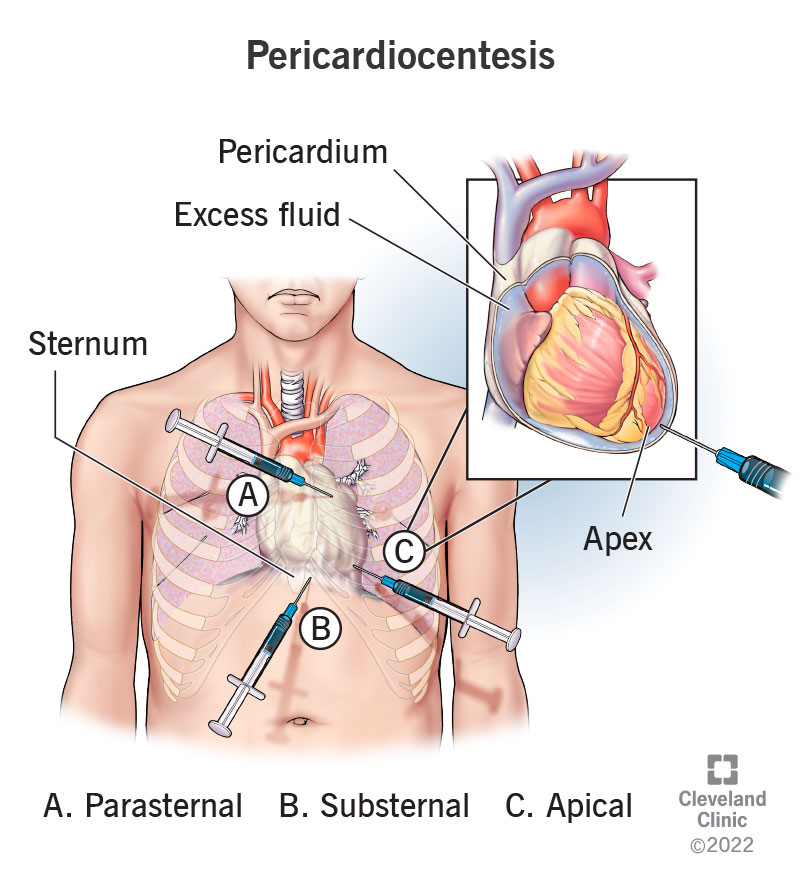
Dry pericardiocentesis is risky because the “target space” is small and the heart can be inadvertently penetrated, while conventional guidance (e.g., fluoroscopy) has limitations and introduces radiation exposure. This patent proposes using bioelectrical impedance as an additional, real-time signal: as the needle advances through different tissues, the measured impedance changes in characteristic ways, helping the operator judge whether the needle tip has reached the pericardial cavity.
Main Content
The disclosed system consists of (1) a hollow puncture needle with proximal and distal voltage-sensing electrodes and internal signal wires, and (2) an external bioelectrical impedance measurement system that injects a controlled sinusoidal current and measures differential voltages to compute impedance.
A key detail is the four-electrode measurement approach: instead of relying on a simpler two-electrode loop (more vulnerable to electrode–tissue contact resistance and polarization effects), separate current injection and voltage sensing are used to reduce measurement distortion and improve robustness in a noisy clinical environment.
System Context
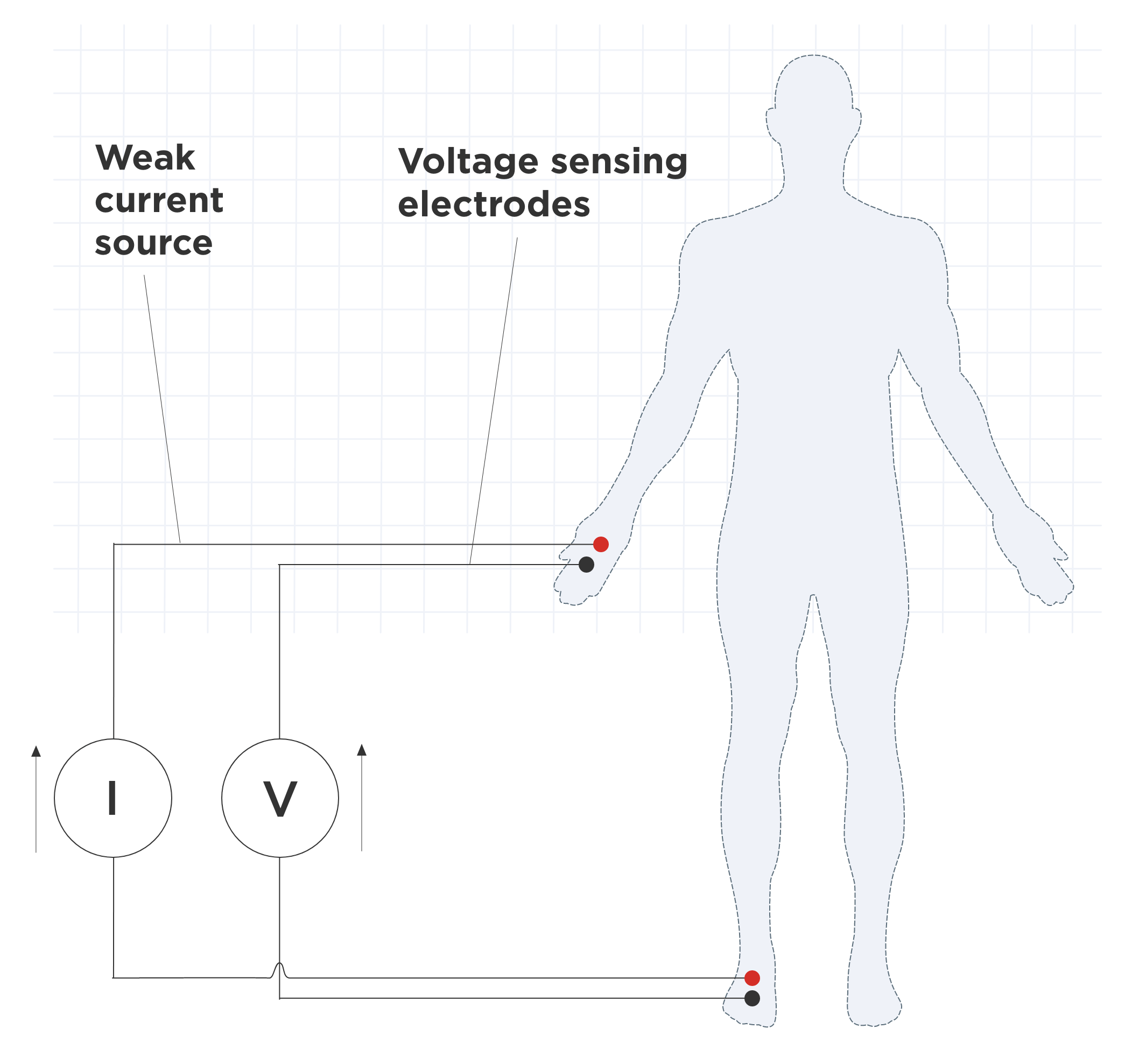
In use, the signal generator outputs a sinusoidal current (described as 50 kHz and ≤100 μA) to establish an electric field in the thoracic region. As the needle progresses, tissue-specific electrical properties create different barriers to current flow, producing different voltage differences between the two sensing electrodes; impedance is computed as and tracked over time to support position judgment.
Architecture / Design Considerations
1) Needle and electrode integration
The puncture needle includes two voltage-measurement electrodes spaced along the needle (example spacing given as 1–3 cm) and insulated wiring routed to an external acquisition system.
The distal electrode can be described as a flexible conductive film (the text mentions graphene film as one option), while the needle body may use conductive, biocompatible alloys.
2) Analog front-end and conversion chain
A differential instrumentation amplifier stage is described (e.g., INA128) with filtering (low-pass and high-pass elements) to condition microvolt-level signals.
A high-resolution ADC is specified (ADS1256, 24-bit), with a reference source and a sampling rate described at ≥10 kHz, enabling fast response (target response time stated as ≤100 ms).
3) Processing, logging, and communications
A main control/data processing module configures acquisition over SPI, computes impedance in real time, and applies smoothing/baseline correction (e.g., moving average windowing is explicitly described).
For connectivity, the patent explicitly includes an Ethernet interface (W5500 chip) to stream impedance data to a hospital system in real time, plus a UART path (via MAX3232) to local peripherals such as a display or printer.
This is not “Ethernet for the sake of Ethernet.” In this architecture, wired networking fits the role of reliable, low-latency transport for continuous physiological telemetry, and it also helps keep the bedside acquisition unit simple while integrating into existing clinical IT networks (where wired links are often the default for medical equipment). The W5500 is a practical fit here because it is a hardwired TCP/IP Ethernet controller designed to reduce host-side networking burden in embedded systems.
4) Safety and interference mitigation
The design emphasizes isolation and protection: digital isolators are used between sensitive front-end signals and the main control domain, TVS protection is placed at ADC inputs, and grounding/PCB layout guidance is provided (partitioning analog/digital domains and controlling return paths).
Possible Implications
Guidance as an additional modality: Impedance monitoring can function as a complementary cue when imaging-based guidance is limited or when subtle “entry events” need clearer detection.
System-level thinking matters: The invention is not only a needle concept; it lays out an end-to-end chain (current injection → sensing → conditioning → conversion → computation → communication), suggesting the authors are targeting reproducible clinical operation rather than a lab demo.
Data integration opportunities: Real-time Ethernet streaming implies the measurements are intended to be consumed by external systems (monitoring dashboards, logging, EMR-adjacent infrastructure), even if the exact software integration is not specified here.
Conclusion
This patent proposes a pericardiocentesis assistance device that uses four-electrode bioelectrical impedance measurement to detect tissue transitions during puncture. By pairing a purpose-built needle electrode layout with a high-resolution acquisition chain and a hospital-facing communication path (including WIZnet W5500 Ethernet), the design aims to improve real-time judgment and procedural safety in difficult dry pericardial access scenarios.
전체 개요
이 특허는 “영상으로 보면서 찌르기”가 늘 최선이 아닌 상황, 특히 심낭에 삼출이 없는(dry) 심낭천자에서 발생하는 위험을 줄이기 위해, 바늘 끝이 지나가는 조직을 전기적 특성(임피던스) 으로 추정해 보조 판단 신호를 제공하려는 접근입니다. 핵심은 바늘이 조직을 통과할 때 조직마다 전기적 성질이 달라서, 측정되는 임피던스가 달라진다는 점을 이용하는 것입니다.
기술 흐름 설명
동작 흐름을 “수술 장면” 기준으로 풀어보면 아래처럼 정리됩니다.
전류를 아주 작고 안전한 범위로 인체에 인가합니다(예: 50 kHz, ≤100 μA로 기술).
바늘이 전진하는 동안, 바늘에 내장된 두 개의 전압 측정 전극(근위/원위) 사이에서 전압차가 생깁니다.
시스템은 형태로 실시간 임피던스를 계산하고, 시간에 따른 변화(급변 등)를 보고 바늘 끝이 어느 조직층에 있는지 판단을 돕습니다.
이렇게 얻은 데이터는 장비 내부에 저장도 하고, 필요하면 병원 시스템으로도 전송하는 구성입니다.
여기서 중요한 점은 “임피던스 측정”을 단순히 센서 하나 붙여서 끝내는 게 아니라, 전류 생성기 + 아날로그 프런트엔드 + ADC + 연산 + 통신을 하나의 체인으로 꽤 구체적으로 제시한다는 점입니다.
왜 이런 구조가 나왔는지에 대한 해설
이 특허가 굳이 4전극(four-electrode) 방식을 강조하는 이유는, 의료 환경에서 바늘 끝 주변의 접촉 상태가 계속 바뀌고(접촉면적, 압력, 조직 상태), 전극-조직 계면에서 생기는 접촉저항/분극이 측정값을 흔들 수 있기 때문입니다. 2전극 방식은 전류를 흘리는 전극과 전압을 재는 전극이 겹치다 보니 이런 영향이 더 크게 들어올 수 있고요.
반대로 4전극 구성은 “전류 인가 경로”와 “전압 측정 지점”을 분리해, 바늘 끝 주변 환경 변화에 따른 오차를 상대적으로 줄이려는 선택으로 해석할 수 있습니다. 물론 실제 임상에서의 유효성은 별도의 검증이 필요하겠지만, 최소한 설계 의도는 “실시간 판단 신호를 안정적으로 뽑겠다”에 맞춰져 있습니다.
(여기 문장은 추론임: 특허 본문이 ‘왜’에 대한 논리를 충분히 설명하기보다, 한계를 나열하고 4전극 구조를 제안하는 방식으로 전개되기 때문에, 설계 의도는 기술 맥락으로 재구성했습니다.)
시스템 구성 및 선택지 해석
1) 아날로그 프런트엔드와 ADC 선택
미세 신호를 다루기 위해 INA128 계열 계측증폭기와 필터 구성을 제시하고, 24-bit ADC(ADS1256)로 분해능과 잡음 성능을 확보하려는 방향이 보입니다.
샘플링 속도(≥10 kHz)와 응답 시간(≤100 ms) 목표가 같이 언급되는데, 이는 “의사가 바늘을 밀어 넣는 동안” 판단 신호가 뒤늦게 나오면 의미가 떨어지기 때문이라고 해석할 수 있습니다.
(이 역시 추론임: 수치 목표 자체는 특허에 있고, 임상 동작 맥락에서 왜 필요한지는 기술 상식으로 연결했습니다.)
2) 전류 발생부(신호 발생기) 구성
ADuC847 기반 DDS로 50 kHz 사인파를 만들고, OPA549를 이용한 트랜스컨덕턴스(정전류) 구조를 제시합니다. 과전류 차단(PPTC)과 절연(ADuM)을 함께 넣어서 “안전과 분리”를 강조합니다.
이 부분은 단순 센서가 아니라 “의료용 신호 인가 장치”로서의 안전장치를 갖추려는 흔적이 분명합니다.
3) 통신: 왜 하필 Ethernet인가
이 특허는 통신 모듈에 Ethernet 인터페이스(W5500 칩) 를 명시하고, 임피던스 데이터를 병원 시스템으로 실시간 전송한다고 적습니다.
여기서 포인트는 “네트워크가 있으면 좋아요”가 아니라, 다음 같은 설계적 이유로 유선 이더넷이 자연스러운 선택지가 될 수 있다는 점입니다.
실시간 텔레메트리에서 지연/손실을 예측 가능하게 만들고,
병원 내 기존 인프라(유선 구간)와 연결하기 쉽고,
임베디드 장치 입장에서는 W5500 같은 하드와이어드 TCP/IP 컨트롤러로 호스트 부담을 줄일 수 있습니다.
단, “반드시 이게 정답” 같은 얘기는 아닙니다. 무선/USB/다른 유선 프로토콜도 설계 목표(격리, 규격, 인증, 운영환경)에 따라 선택될 수 있고, 특허는 그중 한 구성을 구체 예로 제시한 것으로 보는 편이 안전합니다.
내부 관점에서의 시사점
이 특허의 매력은 “바늘에 센서를 단다” 수준이 아니라, 임피던스 측정 체인 전체를 임상 환경에 맞춰 구체화했다는 점입니다. (증폭, 필터, 고분해 ADC, 실시간 연산, 저장, 통신, 절연/보호)
W5500을 통신 경로로 박아 넣은 건, 이 장치가 단독 장난감이 아니라 병원 시스템과 붙어야 하는 장비라는 전제를 깔고 있다는 신호로도 읽힙니다.
4전극 방식은 “임상에서 흔들리지 않는 판단 신호”를 만들기 위한 전형적인 선택지인데, 이 특허는 그 선택을 심낭천자 보조라는 매우 구체적인 절차에 연결해 놓았습니다.
AEO – 자주 묻는 핵심 질문 정리
Q1. 이 특허는 기존 심낭천자 방식의 어떤 한계를 겨냥하나요?
기존 영상 기반 유도 방식이 제한적인 상황, 특히 dry pericardiocentesis에서 바늘 위치 판단이 어려운 문제를 보완하려는 목적입니다. 임피던스를 이용해 조직 변화를 감지함으로써 추가적인 판단 신호를 제공합니다.
Q2. 왜 굳이 4전극 임피던스 측정 방식을 사용하나요?
전극–조직 접촉 상태 변화로 인한 측정 오차를 줄이고, 시술 중 발생하는 환경 변동에도 비교적 안정적인 변화 추이를 얻기 위한 선택으로 해석할 수 있습니다.
Q3. 이 시스템에서 핵심 데이터는 어떻게 생성되고 처리되나요?
소량의 교류 전류를 인가하고, 바늘에 배치된 전압 전극 간 전압 차를 측정해 임피던스를 계산합니다. 이 값은 고해상도 ADC와 디지털 처리 과정을 거쳐 실시간으로 갱신됩니다.
Q4. Ethernet 통신은 이 시스템에서 어떤 역할을 하나요?
측정된 임피던스 데이터를 외부 장비나 병원 시스템으로 안정적으로 전송하는 역할을 합니다. 유선 Ethernet은 지연과 신뢰성 측면에서 의료 환경에 적합한 선택지로 볼 수 있습니다.
Q5. 이 접근은 기존 영상 유도 방식을 대체하나요?
특허의 구성만 보면, 완전한 대체라기보다는 보조 판단 수단으로 사용하는 것이 더 현실적인 해석입니다. 영상, ECG 신호 등과 병행해 사용할 수 있는 추가 정보원에 가깝습니다.
본 특허(CN121059252A)는 중국 광둥성에 위치한 의과대학 부속 병원을 중심으로 한 의료진·기술진 협업 결과로 등록되었습니다. 발명자 구성과 소속을 보면, 단일 연구자가 아닌 임상 현장과 공학적 구현을 동시에 고려한 팀 단위 발명의 성격이 비교적 분명하게 드러납니다.
저자 정보
庞玲品 (Pang Lingpin)
梁曈欣 (Liang Tongxin)
宋孟鸿 (Song Menghong)
黄石安 (Huang Shi’an)
공개된 특허 정보에는 개별 발명자의 상세 이력까지는 명시되어 있지 않으나,
출원인(Assignee)이 Affiliated Hospital of Guangdong Medical University로 등록되어 있다는 점을 고려하면,
이 발명은 다음과 같은 협업 구조에서 나왔을 가능성이 큽니다.
실제 심낭천자 시술을 수행하는 임상의
임상 요구사항을 전자·임베디드 시스템으로 구현하는 의공학 또는 의료기기 개발 인력
(이 해석은 출원 기관의 성격과 특허 내용의 구체성을 근거로 한 합리적 추론임)
출원 기관(Assignee)의 의미
Affiliated Hospital of Guangdong Medical University는
의과대학 교육·연구 기능과 실제 임상 진료가 결합된 기관으로,
다음과 같은 특징을 갖는 연구 환경을 전제합니다.
실험실 아이디어가 아닌 실제 시술 환경에서의 문제 인식
환자 안전, 절차 반복성, 의료 장비 연동 등을 고려한 현실적인 설계 제약
논문 수준의 개념 제안보다, 장비화 가능한 구조 제시에 대한 요구
이 특허가 단순 센서 아이디어를 넘어
아날로그 프런트엔드, 고해상도 ADC, 절연, 그리고 Ethernet(WIZnet W5500) 기반 데이터 전송까지 포함한
상대적으로 완결된 시스템 구성을 제시하는 이유도,
이와 같은 병원 중심 연구 환경의 산물로 해석할 수 있습니다.
저자 정보 관점에서의 해석
이 특허의 저자 구성은 다음과 같은 메시지를 전달합니다.
임상 문제 정의가 먼저 나오고,
그 문제를 해결하기 위한 전기·전자적 구현이 뒤따른 구조
“새로운 알고리즘”이나 “이론적 모델”보다
시술 중 쓸 수 있는 장치 구조에 초점이 맞춰져 있음
따라서 이 발명은
특정 개인의 아이디어라기보다는,
임상 현장의 반복적인 불편과 위험 요소가 누적되어 나온 팀 기반 발명으로 이해하는 편이 자연스럽습니다.
정리
정리하면, CN121059252A는 4전극 생체 임피던스 측정으로 심낭천자 시 바늘 끝 주변 조직 변화를 추적해, 기존 방식(X-ray, ECG 진폭 변화 등)의 한계를 보완하려는 장치 제안입니다. 특히 아날로그/디지털 체인과 안전/절연, 그리고 WIZnet W5500 기반 Ethernet 전송까지 포함해 “현장 장비”에 가까운 형태로 구성 요소를 제시한 점이 특징입니다.