



STM32F103 Multi-Axis Motion Controller with W5500 Ethernet and Industrial I/O
An STM32F103VBTx board combining six isolated stepper axes, 16 sensor inputs, CAN/RS-485, relays, and W5500 Ethernet.
Project Overview
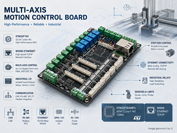
This project is a hardware-centric industrial motion-control board designed for multi-axis point positioning, automated production equipment, industrial manipulators, and coordinated machine control.
The controller integrates an STM32F103VBTx MCU, six optically isolated stepper-driver interfaces, 16 sensor inputs, three relay outputs, CAN, isolated RS-485, and W5500-based Ethernet. The design separates logic, communication, motor-control, and high-power relay sections to reduce interference between control and execution circuits.
The project is best classified as a robotics and industrial automation controller board, rather than a complete robot or finished motion-control product. Motors, external stepper drivers, sensors, mechanical structures, host software, and application-specific firmware must be added separately.
Hardware Architecture
| Module | Confirmed Configuration |
|---|---|
| Main MCU | STM32F103VBTx, LQFP100, identified in the published pin-assignment image |
| Main power input | 15–36 V DC wide-input range |
| Logic supply | 3.3 V |
| Execution supply | 24 V for relays and external actuator circuits |
| Stepper control | Up to six pulse/direction/enable interfaces |
| Stepper isolation | LTV-247 four-channel optocouplers |
| Sensor input | 16 inputs for limit, origin, proximity, and photoelectric sensors |
| Relay output | Three SRD-24VDC-SL-A 24 V relays |
| CAN | SIT1050T high-speed CAN transceiver, described as CAN 2.0A/B compatible |
| RS-485 | Electrically isolated RS-485 interface |
| Ethernet | W5500 hardware TCP/IP Ethernet controller connected through SPI |
| Development environment | FreeRTOS-related attachment, VS Code, STM32CubeMX, and CMake are mentioned |
The project page identifies seven schematic sections covering power, MCU, industrial communication, implementation circuitry, stepper control, sensor inputs, and relay outputs.
System Architecture
15–36 V DC Input
        │
        ├── Power Regulation ──> 3.3 V Logic Domain
        │                         │
        │                         └── STM32F103VBTx
        │                              │
        │                              ├── SPI ──> W5500 ──> Ethernet Host
        │                              ├── CAN ──> Industrial CAN Devices
        │                              ├── Isolated RS-485 ──> Field Devices
        │                              ├── Pulse / Direction / Enable
        │                              │       └── Optocouplers
        │                              │             └── External Stepper Drivers
        │                              ├── 16 Sensor Inputs
        │                              └── 3 Relay-Control Outputs
        │
        └── 24 V Execution Domain
                ├── Relay Coils
                └── External Motion-Control Equipment
The STM32 serves as the central controller. It receives commands through Ethernet, CAN, RS-485, or local serial interfaces, processes sensor and control states, generates stepper-driver control signals, and switches relay-connected field loads.
The published documentation does not confirm whether Ethernet, CAN, and RS-485 operate concurrently in the supplied firmware. Their simultaneous use is supported by the hardware architecture but remains a firmware-dependent capability.
Operation Flow
Motion-Control Path
Host Command
    ↓
Ethernet / CAN / RS-485 / Serial
    ↓
STM32 Command Processing
    ↓
Motion State and Interlock Evaluation
    ↓
Pulse, Direction, and Enable Signals
    ↓
LTV-247 Optical Isolation
    ↓
External Stepper Driver
    ↓
Stepper Motor
Feedback and Execution Path
Limit / Origin / Proximity Sensor
    ↓
16-Channel Sensor Input
    ↓
STM32 Input Processing
    ↓
Motion Stop, Position Sequence, or Equipment Interlock
    ↓
Relay Output or Communication Response
The hardware provides the interfaces required for point-to-point motion and equipment sequencing. However, acceleration profiles, multi-axis interpolation, kinematics, trajectory planning, and encoder-based closed-loop control are not confirmed in the publicly accessible materials.
WIZnet Product Role
WIZnet Product
W5500 Hardware TCP/IP Ethernet Controller
Role in the System
The W5500 provides the wired Ethernet communication path between the STM32 controller and an external host, supervisory computer, or industrial network.
The documented MCU-side signals include an SPI interface and dedicated Ethernet interrupt and reset signals. The W5500 therefore operates as a network coprocessor rather than as a simple Ethernet PHY.
Host PC or Supervisory System
              │
         Ethernet
              │
            W5500
              │
       SPI + INT + RESET
              │
       STM32F103VBTx
              │
   Motion and I/O Control
WIZnet specifies that the W5500 integrates a hardwired TCP/IP stack, 10/100 Ethernet MAC and PHY, socket memory, and an SPI host interface. This architecture reduces the amount of TCP/IP protocol processing required from the STM32.
TOE Assessment
TOE Usage: Yes, at the hardware architecture level
The W5500 performs TCP/IP protocol processing in hardware and is therefore classified as a hardware TCP/IP offload path.
| Implementation Path | Assessment |
|---|---|
| Direct W5500 socket-register control | Not confirmed |
| Arduino Ethernet library | Not indicated |
ESP-IDF esp_eth, esp_netif, or lwIP socket layer | Not applicable and not indicated |
| WIZnet ioLibrary or another framework | Not confirmed |
| Hardware TCP/IP offload | Confirmed by the use of W5500 |
| Ethernet application protocol | Not confirmed |
The accessible project materials do not expose sufficient Ethernet firmware to determine whether the application uses TCP server, TCP client, UDP, Modbus TCP, a proprietary protocol, or another network protocol.
Hybrid Network Assessment
Hybrid Network: No
The board combines Ethernet, CAN, RS-485, serial communication, and local digital I/O, but all confirmed communication paths are wired.
No Wi-Fi, Bluetooth, cellular, LoRa, or other wireless interface is identified in the project. Multiple wired protocols alone do not meet the wired-and-wireless Hybrid Network definition.
Strengths
High Interface Integration
One board combines motion outputs, sensor feedback, relay execution, fieldbus communication, and Ethernet connectivity. This reduces the number of separate interface boards required for small and medium-sized automation systems.
Industrial Communication Coverage
W5500 Ethernet, CAN, and isolated RS-485 provide connections for supervisory systems, distributed equipment, and conventional industrial devices.
Isolation-Oriented Design
Optocouplers are used on the stepper-control paths, while the documentation describes isolation or domain separation for RS-485, Ethernet-related power, and high-power execution circuits. This is relevant in environments containing motors, relays, and long signal cables.
Practical I/O Scale
Six motion-control channels, 16 sensor inputs, and three relay outputs are sufficient for multi-axis fixtures, positioning equipment, feeders, indexing mechanisms, and compact manipulators.
Limitations
Incomplete Firmware Verification
An attachment titled “Code Analysis and Logic Flow” is listed, and the description mentions FreeRTOS code for serial control of MOS and relay outputs. A complete source tree and detailed Ethernet implementation were not available in the accessible project view.
The following items remain unconfirmed:
- W5500 initialization and socket-control implementation
- Host communication protocol
- CAN and RS-485 application protocols
- Multi-axis synchronization accuracy
- Acceleration and deceleration algorithms
- Homing sequence implementation
- Fault recovery and watchdog strategy
- Concurrent network and motion-processing behavior
Open-Loop Motion Interface
The documented motor channels provide pulse, direction, and enable signals to external stepper drivers. Encoder inputs, servo feedback, and closed-loop position control are not explicitly documented.
Limited Validation Data
Network throughput, command latency, pulse jitter, maximum step frequency, input response time, EMC performance, ESD protection level, thermal behavior, and long-term operating results are not published.
Productization Requirements
Emergency-stop architecture, safety relays, safe torque off, redundant limit detection, certified isolation distances, and functional-safety compliance are not confirmed. External safety circuitry would be required for machinery with personnel risk.
Documentation Consistency
The public page and indexed page expose different levels of BOM information, while no 3D model is listed. Component availability and complete manufacturing data should therefore be verified before reproduction.
The project metadata specifies GPL 3.0, while the platform also displays a general notice restricting uploaded projects to learning and research use. Commercial reuse conditions require separate confirmation.
Application Value
This project has practical reference value for:
- Multi-axis point-positioning equipment
- Industrial manipulators and small robotic mechanisms
- Automated production-line fixtures
- Conveyor, feeder, and indexing systems
- Remote industrial I/O controllers
- Educational motion-control platforms
- Ethernet-connected machine-control prototypes
Its principal value lies in the integration of motion control and industrial communication. The W5500 enables deterministic MCU-side network integration without requiring the STM32F103 to run a full software TCP/IP stack.
The board should be regarded as an open hardware controller platform and prototype reference, not as a deployment-ready CNC, PLC, or safety-certified robot controller.
Final Assessment
The project combines a conventional STM32F103 motion-control architecture with a useful range of industrial interfaces. Its six isolated stepper channels, 16 sensor inputs, relay outputs, CAN, RS-485, and W5500 Ethernet provide a strong foundation for compact automation and robotic equipment.
The hardware design is substantially more complete than the publicly verifiable firmware. Its technical value is highest as an expandable controller platform whose communication protocol, motion algorithms, safety functions, and reliability validation can be developed according to the target machine.
Author Information
- OSHWHub account path:
cos90 - Listed project member:
Clouds_are_deep - Platform: OSHWHub / LCSC Open-Source Hardware Platform
- Hardware version: V1.0
- Created: March 1, 2026
- Project page updated: April 2, 2026
- Declared license: GPL 3.0
- Additional author profile information: Not confirmed
W5500 Ethernet과 산업용 I/O를 통합한 STM32F103 다축 모션 제어 보드
프로젝트 개요
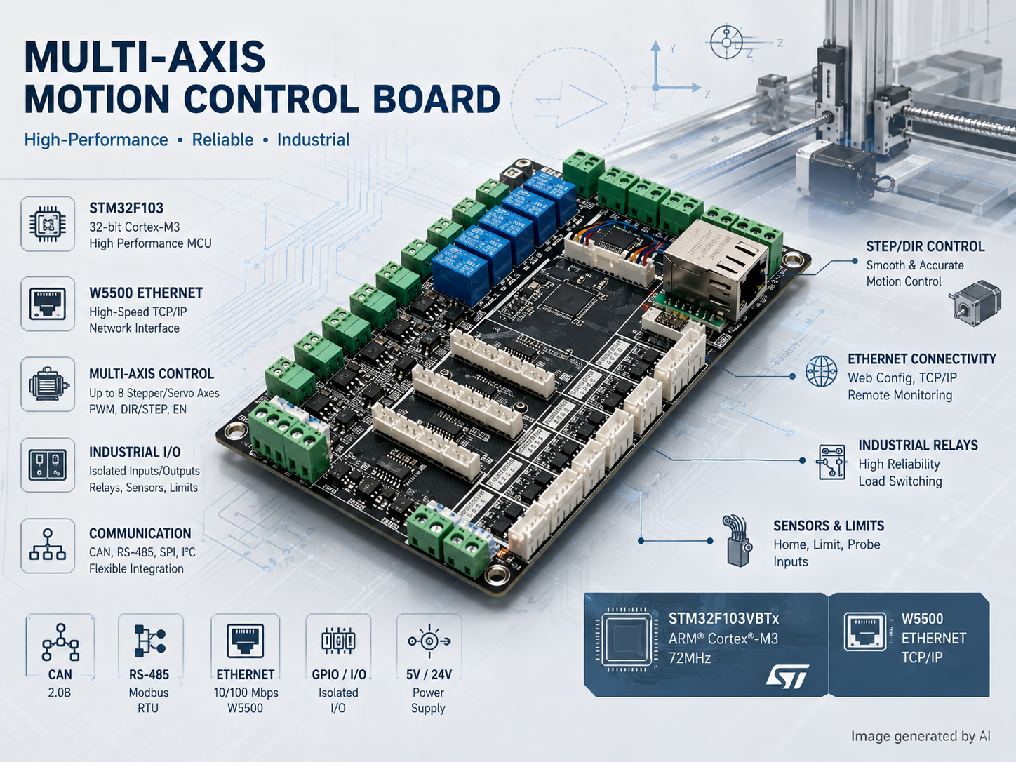
이 프로젝트는 다축 위치 제어, 자동화 생산 장비, 산업용 매니퓰레이터, 설비 연동 제어를 목적으로 설계된 하드웨어 중심의 모션 컨트롤러이다.
STM32F103VBTx MCU를 중심으로 6채널 절연형 스테퍼 드라이버 인터페이스, 16채널 센서 입력, 3채널 릴레이 출력, CAN, 절연형 RS-485, W5500 기반 Ethernet을 하나의 보드에 통합했다. 논리 회로, 통신 회로, 모터 제어 회로, 릴레이 실행 회로를 분리해 모터와 릴레이에서 발생하는 간섭을 줄이는 구조를 사용한다.
완성형 로봇이라기보다 로봇 및 산업 자동화 장비에 장착되는 모션·I/O 제어 보드에 해당한다. 실제 시스템을 구성하려면 외부 스테퍼 드라이버, 모터, 센서, 기구부, 상위 제어 소프트웨어와 목적별 펌웨어가 추가로 필요하다.
주요 하드웨어 구성
| 모듈 | 확인된 구성 |
|---|---|
| 메인 MCU | STM32F103VBTx, LQFP100 |
| 주 전원 입력 | 15–36V DC 광범위 입력 |
| 논리 전원 | 3.3V |
| 실행부 전원 | 릴레이 및 외부 구동 회로용 24V |
| 스테퍼 제어 | 최대 6채널 Pulse·Direction·Enable 출력 |
| 스테퍼 신호 절연 | LTV-247 4채널 포토커플러 |
| 센서 입력 | 16채널 |
| 지원 센서 | 리미트, 원점, 근접 및 광전 센서 등 |
| 릴레이 출력 | SRD-24VDC-SL-A 기반 3채널 |
| CAN | SIT1050T 고속 CAN 트랜시버 |
| RS-485 | 전기적 절연형 RS-485 인터페이스 |
| Ethernet | SPI로 연결되는 W5500 하드웨어 TCP/IP 컨트롤러 |
| 개발 환경 | FreeRTOS 관련 첨부자료, VS Code, STM32CubeMX, CMake 언급 |
공개 자료에는 전원, MCU, 산업 통신, 구현 회로, 스테퍼 제어, 센서 입력, 릴레이 출력으로 구성된 7개 회로도 페이지가 명시되어 있다.
시스템 구조
15–36V DC 입력
        │
        ├── 전원 변환 ──> 3.3V 논리 전원
        │                  │
        │                  └── STM32F103VBTx
        │                       │
        │                       ├── SPI ──> W5500 ──> Ethernet 상위 시스템
        │                       ├── CAN ──> CAN 현장 장비
        │                       ├── 절연 RS-485 ──> 산업용 필드 장비
        │                       ├── Pulse / Direction / Enable
        │                       │       └── 포토커플러
        │                       │             └── 외부 스테퍼 드라이버
        │                       ├── 16채널 센서 입력
        │                       └── 3채널 릴레이 제어
        │
        └── 24V 실행부 전원
                ├── 릴레이 코일
                └── 외부 모션 제어 장비
STM32는 보드 전체의 중앙 제어기로 동작한다. Ethernet, CAN, RS-485 또는 직렬 통신으로 명령을 받고, 센서 상태와 제어 조건을 처리한 뒤 스테퍼 드라이버용 제어 신호와 릴레이 출력을 생성하는 구조이다.
Ethernet, CAN, RS-485를 펌웨어에서 동시에 운용하는지는 확인되지 않았다. 하드웨어는 병행 사용이 가능한 구조이지만, 실제 동시 운용 여부는 펌웨어 구현에 의존한다.
동작 흐름
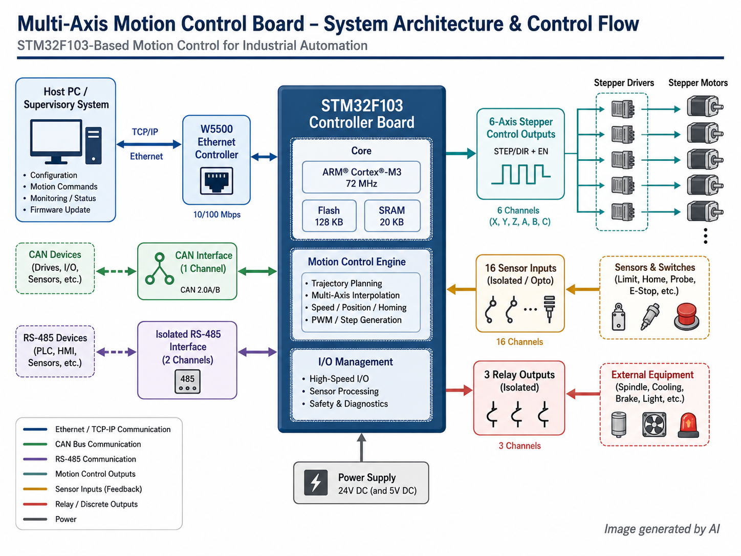
모션 제어 경로
상위 제어 명령
    ↓
Ethernet / CAN / RS-485 / Serial
    ↓
STM32 명령 처리
    ↓
동작 상태 및 인터록 조건 판단
    ↓
Pulse, Direction, Enable 신호 생성
    ↓
LTV-247 광절연
    ↓
외부 스테퍼 드라이버
    ↓
스테퍼 모터 구동
센서 피드백 및 실행 경로
리미트 / 원점 / 근접 센서
    ↓
16채널 센서 입력
    ↓
STM32 입력 처리
    ↓
정지, 원점 복귀, 위치 시퀀스 또는 설비 인터록
    ↓
릴레이 출력 또는 통신 응답
하드웨어는 다축 점 위치 제어와 설비 시퀀스에 필요한 기본 입출력을 제공한다.
다만 다음 기능은 공개 자료에서 확인되지 않는다.
- 가감속 프로파일
- 다축 보간 제어
- 로봇 기구학 계산
- 궤적 계획
- 엔코더 기반 폐루프 위치 제어
- 축간 정밀 동기화 알고리즘
WIZnet 제품 사용 여부와 역할
사용 제품
W5500 Hardware TCP/IP Ethernet Controller
시스템 내 역할
W5500은 STM32 제어 보드와 상위 PC, 감독 제어 시스템 또는 유선 산업 네트워크를 연결하는 Ethernet 통신 경로를 담당한다.
MCU와 W5500 사이에는 SPI 통신과 별도의 Interrupt 및 Reset 신호가 배치되어 있다. 따라서 W5500은 단순 Ethernet PHY가 아니라 TCP/IP 통신을 처리하는 네트워크 보조 프로세서 역할을 수행한다.
상위 PC 또는 감독 제어 시스템
              │
           Ethernet
              │
            W5500
              │
       SPI + INT + RESET
              │
       STM32F103VBTx
              │
      모션 및 I/O 제어
W5500은 TCP/IP 프로토콜 처리 로직, 10/100 Ethernet MAC·PHY, 소켓 버퍼와 SPI 호스트 인터페이스를 내부에 통합한다. 이에 따라 STM32가 전체 소프트웨어 TCP/IP 스택을 직접 처리해야 하는 부담을 줄일 수 있다.
TOE 사용 여부
TOE 사용 여부: 사용
W5500이 TCP/IP 프로토콜을 하드웨어에서 처리하므로 하드웨어 TCP/IP Offload 구조에 해당한다.
다만 공개된 소프트웨어 자료가 제한되어 있어 W5500에 접근하는 구체적인 드라이버 계층은 확인할 수 없다.
| 구현 방식 | 판단 |
|---|---|
| W5500 Socket Register 직접 제어 | 코드상 확인되지 않음 |
| Arduino Ethernet Library 경유 | 사용 근거 없음 |
ESP-IDF esp_eth / esp_netif / lwIP 경유 | 해당 없음 |
| WIZnet ioLibrary 사용 | 코드상 확인되지 않음 |
| 기타 Framework 또는 Driver | 확인되지 않음 |
| W5500 하드웨어 TCP/IP Offload | 확인됨 |
| TCP·UDP 등 실제 응용 프로토콜 | 확인되지 않음 |
W5500 하드웨어는 포함되어 있지만 TCP Server, TCP Client, UDP, Modbus TCP 또는 독자 프로토콜 중 어떤 방식으로 상위 시스템과 통신하는지는 공개 자료에서 확인되지 않는다.
Hybrid Network 여부
Hybrid Network 여부: 해당 없음
이 보드는 Ethernet, CAN, RS-485, Serial 및 로컬 디지털 I/O를 함께 제공하지만, 확인된 통신 방식은 모두 유선이다.
Wi-Fi, Bluetooth, 이동통신, LoRa 등 무선 네트워크 구성은 확인되지 않는다. 여러 종류의 유선 통신을 통합한 것은 산업용 멀티프로토콜 구조이지만, 유선과 무선을 함께 사용하는 Hybrid Network에는 해당하지 않는다.
장점
높은 기능 통합도
모션 출력, 센서 피드백, 릴레이 실행, 필드버스 및 Ethernet을 하나의 보드에 통합했다. 소규모 및 중규모 자동화 장비에서 별도 인터페이스 보드 수를 줄일 수 있다.
산업용 통신 인터페이스
W5500 Ethernet, CAN, 절연형 RS-485를 제공하므로 상위 제어 시스템, 분산 장치 및 기존 산업용 장비와 연결할 수 있다.
절연 중심의 회로 구성
스테퍼 제어 신호에는 포토커플러가 적용되어 있으며, RS-485, Ethernet 관련 전원 영역과 강전 실행부에도 절연 또는 전원 영역 분리 구조가 설명되어 있다. 모터, 릴레이와 장거리 케이블이 함께 사용되는 환경에서 의미가 있는 구성이다.
실용적인 입출력 규모
6채널 모션 제어, 16채널 센서 입력, 3채널 릴레이 출력은 다축 위치 결정 장비, 지그, 피더, 인덱싱 장비 및 소형 매니퓰레이터에 적용할 수 있는 규모이다.
한계
펌웨어 확인 범위 제한
프로젝트에는 ‘코드 해석 및 논리 흐름’이라는 첨부파일이 등록되어 있으며, 설명에는 FreeRTOS 기반의 직렬 통신, MOS 및 릴레이 제어 코드가 포함된 것으로 기재되어 있다. 그러나 공개 페이지에서 전체 소스 트리와 Ethernet 구현을 직접 검증하기는 어렵다.
다음 항목은 확인되지 않는다.
- W5500 초기화 및 Socket 제어 코드
- 상위 시스템 통신 프로토콜
- CAN 및 RS-485 응용 프로토콜
- 다축 동기화 정밀도
- 가감속 제어 알고리즘
- 원점 복귀 시퀀스
- Watchdog 및 오류 복구 구조
- 네트워크 통신과 모션 제어의 동시 실행 방식
개방형 스테퍼 제어 구조
모터 제어부는 외부 스테퍼 드라이버에 Pulse, Direction, Enable 신호를 전달하는 구조이다. 엔코더 입력, 서보 피드백 및 폐루프 위치 제어는 명시되어 있지 않다.
성능 검증 자료 부족
다음 정량 자료는 공개되지 않았다.
- Ethernet 처리량 및 명령 지연
- 스테퍼 펄스 지터
- 최대 출력 펄스 주파수
- 센서 입력 응답 시간
- EMC 및 ESD 내성
- 열 특성
- 장시간 연속 운전 결과
- 통신 오류 발생 시 복구 시간
제품화 시 추가 안전 설계 필요
비상 정지, Safety Relay, Safe Torque Off, 이중화 리미트, 인증된 절연 거리 및 기능 안전 규격 적용은 확인되지 않는다. 사람과 함께 동작하는 산업 기계에 적용하려면 별도의 안전 회로가 필요하다.
제조 자료와 라이선스 확인 필요
접근 방식에 따라 BOM 표시 내용이 다르게 나타나며 3D 모델은 제공되지 않는다. 복제 제작 전 전체 BOM, 부품 수급 가능성 및 제조 파일을 다시 확인해야 한다.
라이선스 항목에는 GPL 3.0이 표시되어 있지만, 플랫폼의 일반 지식재산권 문구에는 학습과 연구 목적에 관한 제한이 함께 표시된다. 상업적 활용 조건은 별도 확인이 필요하다.
적용 가치
이 프로젝트는 다음 분야에서 활용 가능성이 있다.
- 다축 점 위치 제어 장비
- 산업용 매니퓰레이터 및 소형 로봇 기구
- 자동화 생산라인용 지그
- 컨베이어, 피더 및 인덱싱 시스템
- 원격 산업용 I/O 컨트롤러
- 모션 제어 교육 플랫폼
- Ethernet 기반 기계 제어 시제품
핵심 가치는 모션 제어와 산업용 통신의 통합에 있다. W5500을 통해 STM32F103에서 전체 소프트웨어 TCP/IP 스택을 운용하지 않고도 유선 네트워크 기능을 구현할 수 있다.
다만 완성형 CNC, PLC 또는 안전 인증 로봇 컨트롤러보다는 확장 가능한 오픈 하드웨어 제어 플랫폼 및 시제품 레퍼런스에 가깝다.
종합 평가
STM32F103 기반의 전통적인 모션 제어 구조에 W5500 Ethernet, CAN, RS-485와 다양한 산업용 I/O를 결합한 프로젝트이다.
6채널 절연형 스테퍼 제어, 16채널 센서 입력, 릴레이 출력 및 다중 통신 인터페이스는 소형 자동화 장비와 로봇 제어용 기반 하드웨어로 충분한 구성을 제공한다.
하드웨어 설계의 공개 수준에 비해 펌웨어와 성능 검증 자료는 제한적이다. 상위 통신 프로토콜, 모션 알고리즘, 안전 기능 및 장기 신뢰성 검증을 추가하면 산업 자동화용 통합 컨트롤러로 확장할 수 있다.
저자 정보
- OSHWHub 계정 경로:
cos90 - 프로젝트에 표시된 멤버:
Clouds_are_deep - 등록 플랫폼: OSHWHub / 立创开源硬件平台
- 하드웨어 버전: V1.0
- 생성일: 2026년 3월 1일
- 프로젝트 페이지 업데이트: 2026년 4월 2일
- 표시된 라이선스: GPL 3.0
- 추가 저자 프로필: 확인되지 않음
-
yun-dong-kong-zhi-ban
