



[future extend] STM32 Industrial Fault Detection with FFT and Modbus RTU
STM32 monitors vibration, temperature, and current, detects equipment faults with FFT and thresholds, and reports them via Modbus RTU.
1. English Version
Industrial Equipment Fault Detection System: STM32-Based Multi-Sensor Condition Monitoring with FFT and Modbus RTU
One-Line Summary
An STM32-based condition-monitoring design combining vibration FFT, temperature, and current analysis with Modbus RTU reporting for industrial machinery.
Recommended Korean Category: 산업 자동화 / 예지보전(Predictive Maintenance) / 상태 모니터링(Condition Monitoring)
Project Overview
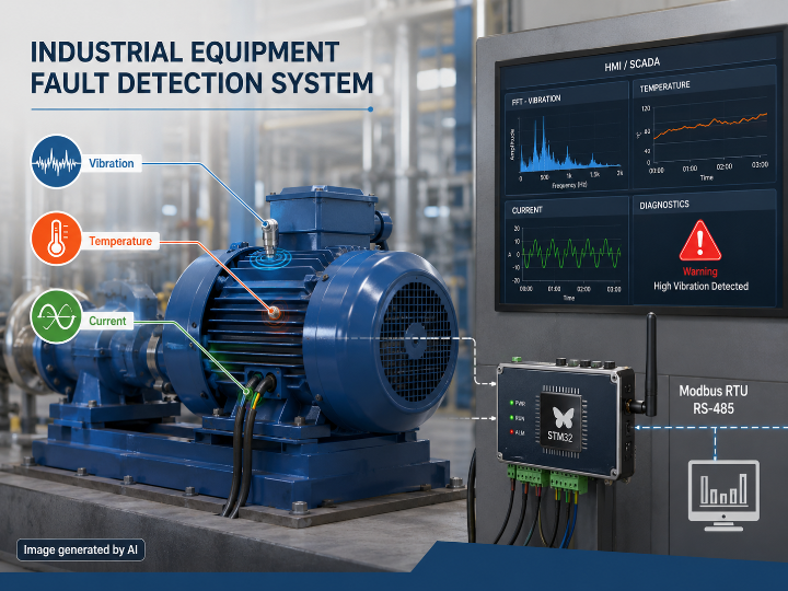
The Industrial Equipment Fault Detection System is designed to monitor rotating machinery such as electric motors, pumps, and conveyor drives. Its proposed architecture acquires vibration, winding-temperature, and phase-current signals, processes them on an STM32F303RE, classifies abnormal conditions, and reports status to a supervisory HMI or SCADA station through Modbus RTU over RS-485.
The system targets four main fault categories:
Bearing degradation based on vibration frequency signatures
Winding overtemperature
Motor overload / overcurrent
Sensor failure caused by open, short, or out-of-range conditions
This is a rule- and signal-processing-based condition-monitoring system, not a machine-learning fault detector in its current documented form. Machine-learning anomaly detection is listed only as a future improvement.
Implementation Status
A significant distinction exists between the architecture described in the README and the files currently published in the repository.
The README describes a complete firmware tree containing STM32 drivers, FFT processing, a fault engine, Modbus RTU, ring-buffer handling, and a Python monitoring application. However, the actual code/ directory currently contains only:
fault_detection_logic.md
modbus_register_map.md
monitor.py
The published monitor.py contains five fixed print() statements rather than the live pymodbus monitoring implementation shown inside the README.
Assessment (inference): the repository currently represents a detailed system design and demonstration reference more strongly than a fully reproducible STM32 firmware implementation.
Hardware Architecture
| Component | Role | Interface |
|---|---|---|
| STM32F303RE | Main fault-detection controller and DSP processor | MCU |
| ADXL345 | Three-axis vibration measurement | SPI |
| PT100 + MAX31865 | Motor winding temperature measurement | SPI |
| ACS712-20A | Motor phase-current measurement | Analog ADC |
| MAX485 | RS-485 physical-layer interface | UART / RS-485 |
| LED + Buzzer | Local fault annunciation | GPIO |
| PC / SCADA / HMI | Remote monitoring and fault-history interface | Modbus RTU |
The README selects the STM32F303RE, an ARM Cortex-M4 MCU with an FPU, for real-time signal processing and CMSIS-DSP FFT operations.
Signal Processing and Fault Detection
Vibration Channel
The proposed ADXL345 path samples vibration at 1600 Hz and processes a 512-sample window. A Hanning window is applied before a real FFT using ARM CMSIS-DSP. The frequency spectrum is then checked around configured BPFO and BPFI bearing frequencies.
For the documented example of a 6205 bearing at approximately 1450 RPM:
BPFO: approximately 86.9 Hz
BPFI: approximately 111.1 Hz
Frequency-band tolerance: ±5 Hz
The README defines vibration severity levels at:
Warning: RMS > 2.0 g
Critical: RMS > 4.5 g
Temperature Channel
The PT100/MAX31865 path evaluates both absolute winding temperature and rate of temperature rise.
Documented thresholds include:
Warning: > 80°C or > 5°C/min
Critical: > 105°C or > 15°C/min
This allows the proposed fault engine to identify not only sustained overheating but also rapid thermal escalation.
Current Channel
The ACS712-20A measures phase current through the STM32 ADC. Current RMS is compared with the configured motor Full Load Current (FLC):
Warning: > 110% FLC
Critical: > 125% FLC
The README also describes averaging 100 ADC samples and applying a first-order IIR filter to reduce ACS712 noise.
System Architecture and Operation Flow
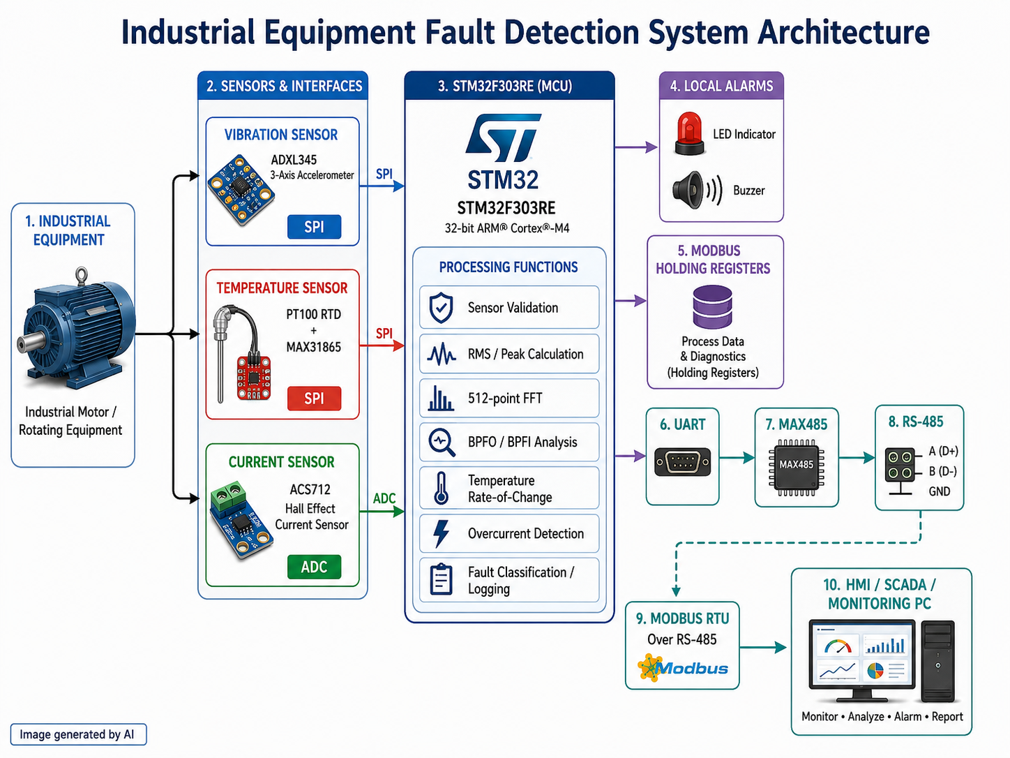
Rotating Equipment
      │
      ├── ADXL345 ─────── Vibration / SPI
      ├── PT100+MAX31865 ─ Temperature / SPI
      └── ACS712 ───────── Phase Current / ADC
      │
      ▼
STM32F303RE
      │
      ├── Sensor validation
      ├── RMS / peak calculation
      ├── 512-point FFT
      ├── BPFO / BPFI analysis
      ├── Temperature rate-of-change
      ├── Overcurrent threshold detection
      └── Fault classification / logging
      │
      ├─────────────► LED / Buzzer
      │
      ▼
Modbus Holding Registers
      │
      ▼
UART → MAX485 → RS-485
      │
      ▼
Modbus RTU
      │
      ▼
SCADA / HMI / Monitoring PC
The documented runtime design begins with sensor self-tests, followed by high-rate vibration and current acquisition and lower-rate temperature sampling. Fault processing updates status registers and local alarms while Modbus RTU requests are intended to run through interrupt-driven UART handling.
The README specifically describes moving Modbus communication away from polling and into UART interrupt-driven operation with a 128-byte ring buffer to avoid interference with sensor acquisition.
Modbus Data Interface
The published modbus_register_map.md exposes six holding-register functions:
| Register | Data |
|---|---|
| 40001 | Temperature |
| 40002 | Current |
| 40003 | Vibration RMS |
| 40004 | Fault Code |
| 40005 | Fault Severity |
| 40006 | System Status |
The documented fault codes are Normal, Overtemperature, Overcurrent, Excessive Vibration, and Bearing Fault Signature.
The README contains a more extensive register map with additional peak-frequency, fault-count, uptime, and fault-log fields. This differs from the smaller register map currently published as a standalone file.
WIZnet Product / TOE / Hybrid Network Assessment
WIZnet Product Role
WIZnet Product Role: No WIZnet product is implemented in the currently published repository.
The active communication architecture is:
STM32F303RE
    │ UART
    ▼
MAX485
    │ RS-485
    ▼
Modbus RTU
    ▼
SCADA / HMI
No W5500, W5100S, W6100, W6300, ioLibrary, Ethernet driver, or TCP/IP socket implementation is present in the currently published code tree.
The README mentions W5500 only as a future improvement, proposing migration from Modbus RTU to Modbus TCP over an SPI-connected W5500 for plant-wide Ethernet connectivity.
TOE Usage
TOE Usage: No
There is no implemented Ethernet or TCP/IP path and therefore no current WIZnet TCP/IP Offload Engine usage. Communication is based on Modbus RTU over RS-485.
A future W5500-based Modbus TCP implementation could introduce hardware TCP/IP offload, but that functionality is not part of the current repository.
Hybrid Network
Hybrid Network: No
The documented system uses a single wired RS-485/Modbus RTU communication path. Wi-Fi, Bluetooth, cellular, LoRa, or another simultaneous wireless network is not implemented.
The proposed W5500 migration would replace or extend the wired communication path with Ethernet, but Ethernet alone would still not constitute a Hybrid Network.
Strengths
Multi-Parameter Fault Detection
The architecture combines three different physical indicators instead of relying on a single threshold:
Mechanical vibration
Thermal behavior
Electrical current
This allows bearing, winding, overload, and sensor faults to be represented through different signal domains.
Embedded Frequency-Domain Analysis
The proposed use of a 512-point FFT and BPFO/BPFI frequency analysis moves bearing-condition detection onto the MCU rather than relying entirely on an external PC.
Industrial Communication Model
Modbus RTU and a defined register map provide a recognizable interface between the embedded fault node and conventional HMI/SCADA systems.
Attention to Real-Time Acquisition
The README documents DMA-based acquisition and interrupt-driven Modbus communication to reduce blocking between measurement and supervisory communication.
Limitations
Incomplete Published Firmware
The largest limitation is reproducibility. The README describes source files such as main.c, sensor drivers, fft_analysis.c, fault_engine.c, and modbus_rtu.c, but these files are not present in the currently visible code/ directory.
Monitoring Software Gap
The README presents a Python pymodbus live-monitoring example, while the actual monitor.py only prints fixed example values. Live serial acquisition and plotting therefore cannot be verified from the published Python file.
Validation Evidence
The README lists test scenarios including vibration, heating, overcurrent, Modbus, ring-buffer, and 30-minute GUI tests. However, the detailed firmware and test implementation needed to independently reproduce these results is not currently available in the repository tree.
WIZnet Integration
W5500 integration exists only in the future roadmap. There is currently no Ethernet hardware implementation, Modbus TCP source, socket code, or WIZnet driver.
Application Value
Assessment (inference): the project has value primarily as an architectural reference for embedded condition monitoring and industrial predictive-maintenance concepts.
Its combination of multi-sensor acquisition, embedded FFT, threshold-based fault classification, local alarm handling, and Modbus register mapping demonstrates how a compact field monitoring node can be structured. The architecture can be extended toward Ethernet-based industrial monitoring by replacing or supplementing the RS-485 communication layer.
From a WIZnet perspective, the most relevant path is the explicitly proposed STM32 + W5500 + Modbus TCP evolution. This remains a future design direction rather than an implemented WIZnet application.
Author Information
The repository is maintained by MUHAMMAD UMAIR AHMED, GitHub account aaka71056. The author's GitHub profile also contains STM32 and industrial-automation projects, while this repository is described as an industrial automation engineering portfolio project focused on condition monitoring and predictive maintenance.
Final Summary
The Industrial Equipment Fault Detection System defines an STM32F303RE-based condition-monitoring architecture using ADXL345 vibration sensing, PT100/MAX31865 temperature measurement, ACS712 current monitoring, embedded FFT processing, and Modbus RTU over RS-485.
Its technical concept is relatively detailed, including bearing-frequency analysis, fault thresholds, register mapping, event logging, and non-blocking communication design. However, much of the firmware shown or referenced in the README is not currently present as executable source files in the repository, so the project should be regarded as a partially published engineering reference rather than a fully reproducible implementation.
WIZnet: Not currently used
TOE: No
Hybrid Network: No
W5500: Mentioned only as a future Modbus TCP/Ethernet migration option.
STM32 기반 산업 설비 고장 감지 시스템: 다중 센서·FFT 분석과 Modbus RTU 기반 상태 모니터링
프로젝트 개요
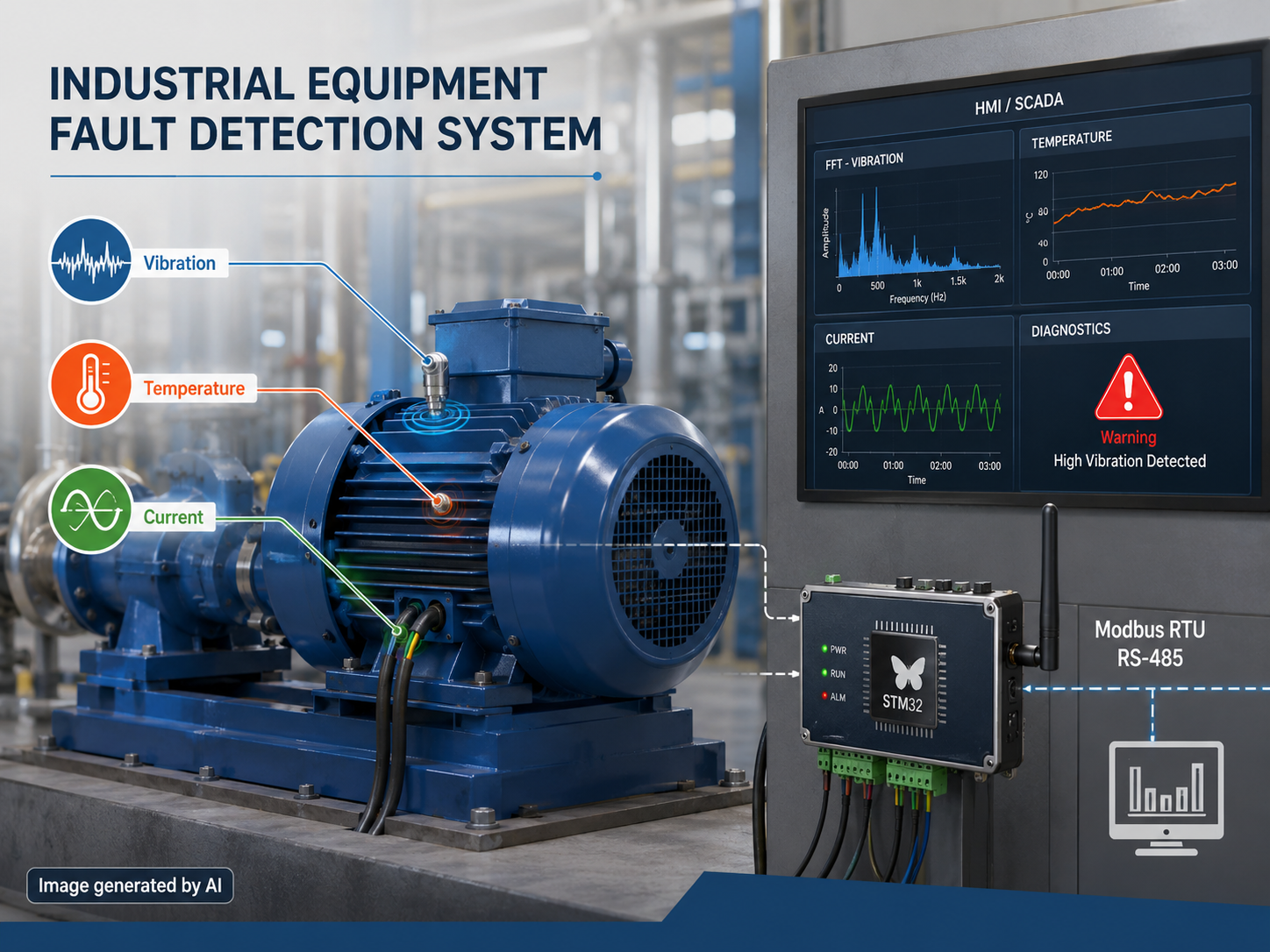
Industrial Equipment Fault Detection System은 전동기, 펌프, 컨베이어 드라이브와 같은 회전 설비의 상태를 감시하기 위한 시스템이다. ADXL345로 진동, PT100/MAX31865로 권선 온도, ACS712로 상전류를 측정하고 STM32F303RE에서 데이터를 처리한 뒤 RS-485 기반 Modbus RTU를 통해 HMI 또는 SCADA로 상태를 전달하는 구조가 제시되어 있다.
주요 감지 대상은 다음 네 가지다.
베어링 열화 및 이상 진동
모터 권선 과열
모터 과부하 및 과전류
센서 단선·단락·비정상 범위에 의한 센서 고장
현재 구조는 AI나 머신러닝 기반 고장 예측 시스템이 아니라 신호 처리와 임계값 기반의 Condition Monitoring 시스템이다. 머신러닝 기반 이상 탐지는 향후 개선 항목으로만 제시되어 있다.
공개 구현 범위
README에 설명된 구조와 실제 저장소에 공개된 파일 사이에는 차이가 있다.
README에는 main.c, 센서 드라이버, fault_engine.c, fft_analysis.c, modbus_rtu.c, 링 버퍼, Python GUI 등을 포함한 상당한 규모의 소스 구조가 제시되어 있다. 그러나 현재 실제 code/ 디렉터리에서 확인되는 파일은 다음 세 개다.
fault_detection_logic.md
modbus_register_map.md
monitor.py
또한 README 안에는 pymodbus를 이용한 실시간 모니터링 코드가 제시되어 있지만, 실제 저장소의 monitor.py는 온도·전류·진동·상태를 고정 문자열로 출력하는 5줄짜리 예제다.
판단(추론): 현재 공개 상태만 기준으로 하면 완성된 STM32 펌웨어 프로젝트라기보다는 상세한 시스템 설계 및 구현 컨셉을 정리한 엔지니어링 레퍼런스 성격이 강하다.
하드웨어 구성
| 구성 요소 | 역할 | 인터페이스 |
|---|---|---|
| STM32F303RE | 센서 처리 및 고장 판단 메인 MCU | MCU |
| ADXL345 | 3축 진동 측정 | SPI |
| PT100 + MAX31865 | 모터 권선 온도 측정 | SPI |
| ACS712-20A | 모터 상전류 측정 | Analog ADC |
| MAX485 | RS-485 물리 계층 | UART / RS-485 |
| LED + Buzzer | 현장 경고 표시 | GPIO |
| PC / SCADA / HMI | 원격 상태 및 고장 모니터링 | Modbus RTU |
STM32F303RE는 Cortex-M4와 FPU를 갖춘 MCU로 제시되며, ARM CMSIS-DSP를 이용한 실시간 FFT 분석을 담당하도록 설계되어 있다.
고장 감지 방식
1. 진동 및 베어링 이상
ADXL345에서 진동 데이터를 1600 Hz로 수집하고 512개 샘플 단위로 처리하는 구조가 제시되어 있다. FFT 전에 Hanning Window를 적용하고 CMSIS-DSP의 Real FFT를 수행한 뒤 스펙트럼에서 베어링의 BPFO/BPFI 주파수 영역을 검색한다.
README의 6205 베어링 및 약 1450 RPM 예에서는 다음 주파수가 사용된다.
BPFO: 약 86.9 Hz
BPFI: 약 111.1 Hz
탐색 허용 범위: 기준 주파수 ±5 Hz
진동 RMS 기준은 다음과 같이 제시된다.
Warning: 2.0 g 초과
Critical: 4.5 g 초과
2. 권선 온도
PT100과 MAX31865를 통해 권선 온도를 측정하며 절대 온도와 온도 상승률을 함께 검사한다.
Warning: 80°C 초과 또는 5°C/min 초과
Critical: 105°C 초과 또는 15°C/min 초과
따라서 단순 과열뿐 아니라 짧은 시간에 온도가 급격하게 증가하는 상황도 감지 대상으로 삼는다.
3. 과전류
ACS712-20A의 아날로그 출력을 STM32 ADC로 수집하여 RMS 전류를 계산하고 모터 명판상의 Full Load Current(FLC)와 비교한다.
Warning: FLC의 110% 초과
Critical: FLC의 125% 초과
README에는 ACS712의 저부하 구간 노이즈를 줄이기 위해 100개 ADC 샘플 평균과 1차 IIR 필터를 적용한 것으로 설명되어 있다.
시스템 구조와 동작 흐름
산업용 회전 설비
      │
      ├── ADXL345 ─────── 진동 / SPI
      ├── PT100+MAX31865 ─ 온도 / SPI
      └── ACS712 ───────── 전류 / ADC
      │
      ▼
STM32F303RE
      │
      ├── 센서 Self-Test
      ├── RMS / Peak 계산
      ├── 512-point FFT
      ├── BPFO / BPFI 분석
      ├── 온도 변화율 계산
      ├── 과전류 임계값 검사
      └── Fault 분류 및 로그 저장
      │
      ├─────────────► LED / Buzzer
      │
      ▼
Modbus Holding Register
      │
      ▼
UART → MAX485 → RS-485
      │
      ▼
Modbus RTU
      │
      ▼
SCADA / HMI / Monitoring PC
시스템 시작 시 ADXL345, MAX31865, ACS712 상태를 검사하고 정상인 경우 센서 수집을 시작하도록 구성되어 있다. 진동은 512-sample 버퍼, 전류는 ADC DMA, 온도는 상대적으로 낮은 주기로 수집하는 흐름이 README에 설명되어 있다.
센서 데이터 처리가 완료되면 진동 RMS와 FFT, 온도 변화율, 전류 RMS를 계산하고 임계값을 검사한 뒤 Fault 상태와 Modbus Register를 갱신한다. Critical 상태에서는 LED와 Buzzer 등 로컬 경고 장치도 동작하도록 구성되어 있다.
통신 처리로 센서 샘플링이 지연되는 문제를 줄이기 위해 Modbus RX/TX를 UART Interrupt와 128-byte Ring Buffer 기반으로 변경했다는 설계 설명도 포함되어 있다.
Modbus 데이터 구조
현재 공개된 modbus_register_map.md에는 다음 Holding Register가 정의되어 있다.
| Register | 데이터 |
|---|---|
| 40001 | Temperature |
| 40002 | Current |
| 40003 | Vibration RMS |
| 40004 | Fault Code |
| 40005 | Fault Severity |
| 40006 | System Status |
Fault Code는 Normal, Overtemperature, Overcurrent, Excessive Vibration, Bearing Fault Signature로 구성된다.
다만 README에는 Peak Frequency, Fault Count, Uptime, Fault Event Log 등을 추가한 더 큰 Register Map이 제시되어 있어 실제 modbus_register_map.md와 내용에 차이가 있다.
WIZnet 제품 사용 여부
WIZnet Product Role
WIZnet Product Role: 저장소 내 실제 WIZnet 제품 사용은 확인되지 않음
현재 제시된 통신 구조는 다음과 같다.
STM32F303RE
     │ UART
     ▼
MAX485
     │
     ▼
RS-485
     │
     ▼
Modbus RTU
     │
     ▼
SCADA / HMI
실제 공개된 code/ 트리에는 W5500, W5100S, W6100, W6300, ioLibrary, Ethernet Driver 또는 TCP/IP Socket 구현이 존재하지 않는다.
다만 README의 Future Improvements에는 향후 통신을 W5500 SPI 모듈 기반 Modbus TCP over Ethernet으로 확장한다는 계획이 명시되어 있다.
즉, W5500은 현재 프로젝트 구성품이 아니라 향후 Ethernet 확장 후보다.
TOE 사용 여부
TOE 사용 여부: No
현재 구현은 TCP/IP가 아닌 RS-485 기반 Modbus RTU 구조이므로 WIZnet의 TCP/IP Offload Engine을 사용하는 경로가 없다.
향후 W5500을 적용해 Modbus TCP로 전환할 경우 W5500의 Hardware TCP/IP Stack을 활용할 수 있지만, 해당 구현은 현재 저장소에서 확인되지 않는다.
Hybrid Network 여부
Hybrid Network: No
현재 시스템에서 확인되는 통신 네트워크는 RS-485 기반 유선 Modbus RTU 하나다. Wi-Fi, Bluetooth, LoRa, Cellular 등의 무선 네트워크가 Ethernet 또는 RS-485와 함께 동작하는 구조는 확인되지 않는다.
향후 W5500을 추가하더라도 Ethernet만 추가되는 경우 유선 네트워크 확장일 뿐 Hybrid Network로 분류되지는 않는다.
장점
다중 물리량 기반 상태 판단
진동, 온도, 전류라는 서로 다른 특성의 데이터를 함께 사용하므로 단일 센서 기반 시스템보다 다양한 고장 현상을 표현할 수 있는 구조다.
MCU 내부 FFT 분석
진동 데이터를 외부 서버에 전송한 뒤 분석하는 방식이 아니라 STM32에서 512-point FFT와 BPFO/BPFI 분석을 수행하도록 설계되어 Edge Condition Monitoring 구조를 갖는다.
산업 현장과 연결하기 쉬운 데이터 모델
Modbus RTU와 Holding Register 구조를 사용하므로 전통적인 HMI·SCADA 시스템과 연결하기 쉬운 구조를 갖는다.
Blocking 최소화를 고려한 구조
README에는 DMA 센서 수집과 UART Interrupt 기반 Modbus 처리를 병행하는 구조가 설명되어 있어 센서 샘플링과 통신이 서로 간섭하는 문제를 고려하고 있다.
한계
실제 펌웨어 소스 부족
README에는 STM32용 C99 펌웨어와 여러 Driver 및 DSP 모듈이 존재하는 것처럼 구성도가 제시되어 있지만, 현재 공개 저장소의 code/ 디렉터리에서는 해당 .c/.h 파일을 확인할 수 없다.
따라서 센서 Driver, DMA 동작, FFT 처리, Fault Engine, Modbus RTU Slave 구현의 실제 코드 수준 완성도는 검증하기 어렵다.
Python Monitoring GUI 미구현
README의 예시는 pymodbus와 matplotlib를 이용해 Modbus 값을 실시간으로 읽고 그래프로 표시하지만, 실제 monitor.py는 고정 값을 출력하는 단순 예제다.
시험 결과 재현성 제한
README에는 베어링 이상, 열풍기 온도 시험, 과전류 시험, Modbus 통신 시험, Ring Buffer 시험, GUI 30분 연속 동작 등의 검증 항목이 기술되어 있다. 그러나 이를 독립적으로 재현할 전체 펌웨어와 테스트 자료는 현재 공개 구조에서 확인하기 어렵다.
WIZnet 구현 부재
W5500은 Future Improvement에만 등장한다. 현재 Ethernet 회로, W5500 SPI Driver, ioLibrary, Socket API 또는 Modbus TCP 구현은 확인되지 않는다.
적용 가치
판단(추론): 현재 프로젝트의 주요 가치는 완제품 코드보다는 산업용 Edge Condition Monitoring 시스템을 어떻게 구성할 수 있는지 보여주는 설계 레퍼런스에 있다.
진동·온도·전류 센서 수집부터 MCU 내부 Signal Processing, Fault Classification, Local Alarm, Modbus Register Mapping, SCADA 연결까지 전체 흐름이 한 구조 안에 정리되어 있어 산업용 예지보전 노드의 기본 아키텍처를 이해하는 데 활용할 수 있다.
WIZnet 관점에서는 향후 다음 구조로 확장할 가능성이 가장 직접적이다.
현재
STM32
  │
MAX485
  │
Modbus RTU
  ▼
SCADA

        ↓ Ethernet 확장

STM32
  │ SPI
  ▼
W5500
  │ Ethernet / TCP
  ▼
Modbus TCP
  │
  ▼
Plant Network / SCADA
이는 RS-485 세그먼트 중심의 설비 감시 노드를 Ethernet 기반 공장 네트워크로 확장하는 전형적인 경로다. 다만 저장소의 현 상태에서는 이 부분이 구현 결과가 아닌 향후 계획이라는 구분이 필요하다.
저자 정보
저장소 관리자는 GitHub 계정 aaka71056, 프로필명 MUHAMMAD UMAIR AHMED다. 해당 계정에는 STM32 환경 모니터링과 PLC 모터 제어 등 임베디드·산업 자동화 관련 프로젝트도 공개되어 있다.
README에서는 이 프로젝트를 Condition Monitoring과 Predictive Maintenance 설계 역량을 보여주기 위한 Industrial Automation Engineering Portfolio의 일부로 설명한다.
-
industrial-fault-detection-system
