
STM32 Bootloader Workspace for Multi-Image Firmware Isolation
A STM32 firmware architecture workspace showing bootloader handoff, multi-image partitioning, and team-level binary isolation, with W5500 only partially prepare
STMicroelectronics - STM32H533RE
x 1

WIZnet - W5500
x 1
1. Project Overview
STM32-Bootloader-DFU-project is best read as a STM32 firmware-update and bootloader experimentation workspace rather than as one single polished DFU product. The repository contains many separate STM32 projects, including classic bootloader/application examples, UART/IAP-related experiments, USB-related folders, an eth_w5500 hardware-preparation project, and a more coherent Phase-2 multi-application proof of concept. GitHub shows the repository as public, with 44 commits, C as the dominant language, and no published releases at the time checked.
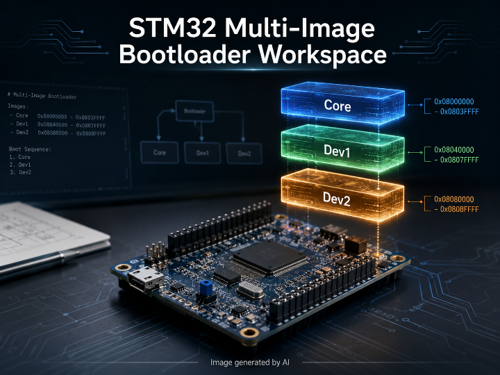
The strongest technical center is the Phase-2 multi-app design. It addresses a practical firmware ownership problem: when one developer or team changes one feature, the full source tree should not have to be shared with every other contributor. The README describes three physically separate firmware images produced by separate teams, where each team receives only the headers and binary interfaces it needs rather than all implementation code.
The result is a useful firmware architecture study: a Core image owns HAL, board initialization, common services, and boot flow; Dev1 and Dev2 are independent binary modules placed in fixed flash regions. The system is less about field OTA delivery and more about controlled firmware partitioning, binary handoff, and API-level separation inside one STM32 device. Tiny tragedy of engineering: the repo name says DFU, the folder list says “everything everywhere all at once,” and the actual best idea is hidden in the middle like buried treasure under auto-generated Cube files.
2. System Structure and Operation Flow
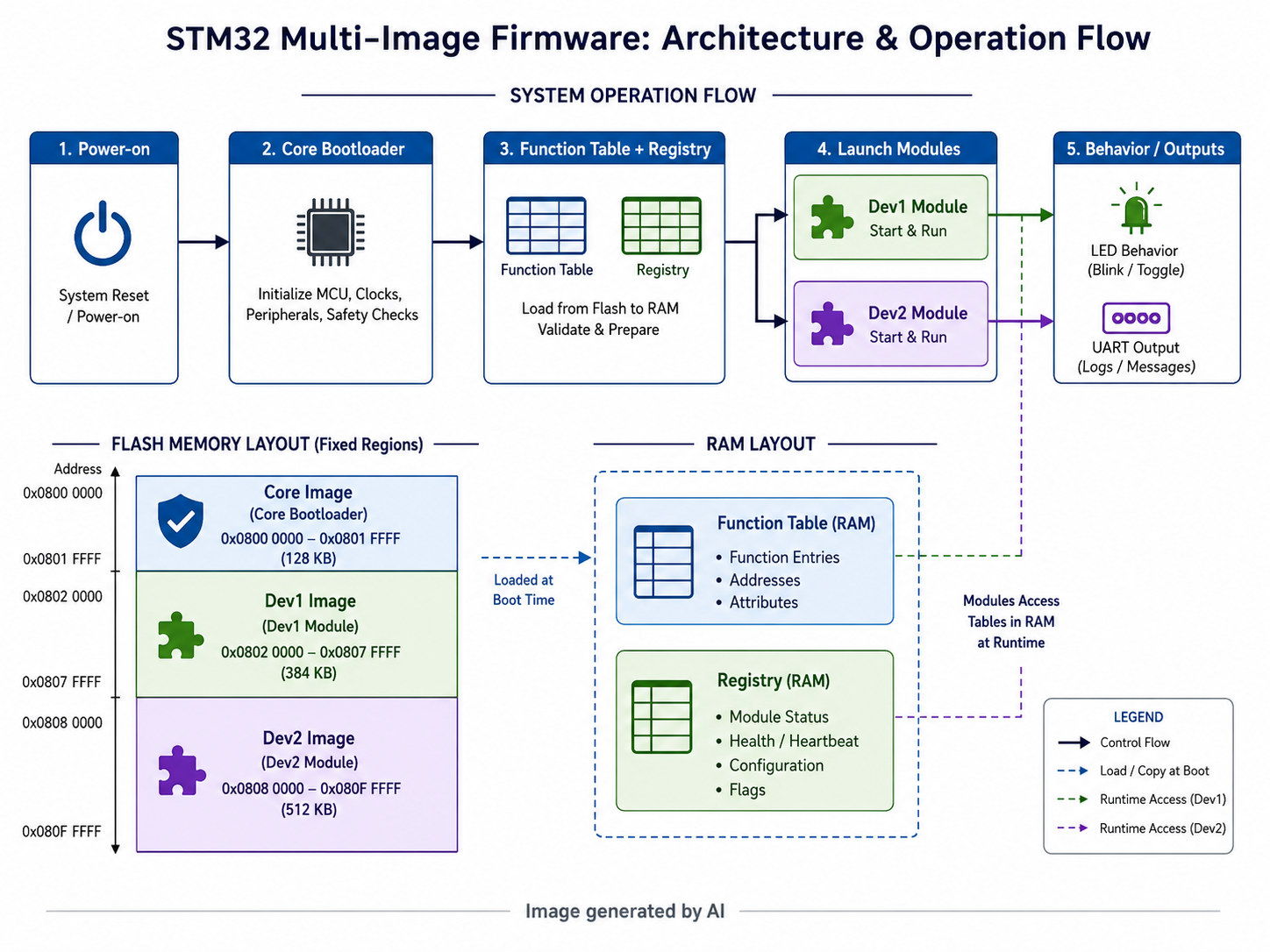
The Phase-2 design divides the STM32H533RE flash into fixed ownership windows. The Core image occupies 0x08000000-0x08019FFF, Dev1 occupies 0x0801A000-0x08029FFF, and Dev2 occupies 0x0802A000-0x08039FFF; RAM also has fixed regions for the function table, registry, Core state, Dev1 .bss, and Dev2 .bss.
The boot process is built around a module entry convention. Each module places the absolute address of its startup function in the first four bytes of its flash region. The Core reads that first word and jumps through it, so the module does not need to be linked into the Core firmware image.
The Core firmware initializes HAL, GPIO, UART, the function table, and the registry, prints a boot message, dumps the registry, and then launches Dev1 and Dev2. The raw main.c confirms this flow: HAL_Init(), peripheral setup, CoreAPI_Init(), Registry_DumpAll(), and CoreAPI_LaunchModules() form the execution spine.
Dev1 publishes a switch-reading service into the shared function table and registry. Dev2 consumes that function table slot without knowing the HAL implementation or Dev1 internals. Dev2 then polls Switch_GetState, drives the LED through the function table, and prints UART state changes.
A simpler classic bootloader path also exists. In bootloader_project, the bootloader reads an application stack pointer and reset handler from 0x08004000, checks a magic value at 0x08004200, and jumps to the application when the magic value matches 0xDEADBEEF. The paired Application_Project places that magic value in a dedicated section and runs a basic UART/LED loop.
3. Core Technical Context
The most important technical idea is not DFU itself, but binary boundary management inside embedded firmware.
The Phase-2 architecture uses three mechanisms:
- Fixed flash ownership
Each firmware image has its own flash window. A team can rebuild and reflash one binary without overwriting the others. - Function table dispatch
The Core exposes primitive services such as LED, UART, delay, GPIO read, and GPIO write through a function table at a fixed RAM address. Dev modules call those function pointers instead of linking HAL code directly. The shared API explicitly says Dev1 and Dev2 receive only headers and do not link against HAL. - Registry-based visibility
A registry at a fixed RAM address records component ownership, version, build number, date, and function address. This makes the demo observable over UART without requiring every module to expose its internal implementation.
This structure gives the repository a different character from ordinary “jump to application” bootloader examples. The simpler bootloader/app pair proves basic vector-table handoff and application validation. The Phase-2 work moves toward modular firmware ownership, where binary interfaces matter more than a single firmware file. The README is honest about the boundary: the design demonstrates distribution-side source separation, but it does not protect against physical flash dumping or reverse engineering; secure boot, signed firmware, TrustZone, and RDP are outside the Phase-2 scope.
4. WIZnet Role and Network Perspective
The repository contains an eth_w5500 project, and the CubeMX configuration shows SPI1 plus CS and RESET GPIO signals suitable for preparing a W5500-style SPI Ethernet hardware connection. The generated main.c initializes SPI1, UART2, GPIO, CS, and RESET pins.
That is where the confirmed WIZnet path stops. The checked eth_w5500 source does not show WIZnet ioLibrary headers, W5500 register access, socket APIs, TCP/UDP calls, firmware download logic, or integration with the Phase-2 multi-image boot flow. Therefore, W5500 should be described as a hardware-preparation or early Ethernet experiment inside the workspace, not as the confirmed transport layer of the main bootloader architecture.
TOE use is also not confirmed. A TOE-based W5500 implementation would normally expose calls such as WIZnet socket operations, chip initialization, network configuration, send, recv, connect, or equivalent ioLibrary paths. The visible eth_w5500 code only confirms SPI/GPIO setup, so the current evidence does not support a claim that W5500’s TCP/IP offload engine is used in the bootloader or module-update flow. Painfully inconvenient, yes, but evidence continues to be annoyingly superior to wishful thinking.
5. Comparison with Existing Maker Content
- STM32_OTA_Bootloader_W5500
- Link: https://maker.wiznet.io/matthew/projects/stm32-ota-bootloader-w5500/?serob=rd&serterm=year
- Similarity: Both deal with STM32 bootloader architecture and firmware update concepts. Both can be discussed around firmware image staging, boot control, and update reliability.
- Difference: The Maker project is a confirmed W5500 Ethernet OTA design. It describes STM32F103 receiving firmware from a PC TCP server through W5500, storing it in W25Q64 external flash, validating it, and installing it after reset. It also explicitly describes W5500 socket-level use and TOE-style operation.
- Connection Value: Reading both together separates two topics that are often mixed up: W5500-based firmware transport versus internal firmware partitioning. The Maker project shows the network update path; the target repository shows modular firmware ownership and binary separation.
- STM32 W5500 OTA功能 - bootloader及app的設計和實現
- Link: https://maker.wiznet.io/ssekim/projects/stm32-w5500-ota-bootloaderapp/
- Similarity: Both are centered on STM32 bootloader/app separation. Both involve boot handoff, flash areas, and firmware replacement logic.
- Difference: The Maker content argues for W5500 because a hardware TCP/IP stack can reduce bootloader memory and code burden. It discusses TCP/IP support, memory constraints, and W5500’s built-in stack as the reason network bootloaders become practical.
- Connection Value: The comparison makes the target repository’s boundary clearer. Its current strength is firmware image separation and module dispatch, while the Maker content explains why W5500 matters when the missing piece is network transport.
- How to flash the OTA update from the STM32 Bootloader
- Link: https://maker.wiznet.io/jaden/projects/how-to-flash-the-ota-update-from-the-stm32-bootloader/?page=2&serob=rd&serterm=year
- Similarity: Both address STM32 bootloader update flows and firmware image management.
- Difference: The Maker content presents W5500 as a TCP transport option for Ethernet OTA and frames the architecture around repeated firmware delivery over a wired network.
- Connection Value: This gives a useful ladder: first understand STM32 bootloader logic, then understand W5500 Ethernet delivery, then compare that with the target repository’s multi-binary isolation model.
6. Position Compared with Existing Cases
Against W5500 OTA examples, the target repository sits one layer inward. Existing Maker W5500 OTA cases focus on how firmware reaches the device over Ethernet. The target repository focuses on what happens once firmware is split into multiple independently owned regions inside the device.
Functionally, the target repository is closer to a modular firmware ownership demo than to a complete OTA bootloader. Implementation-wise, it uses fixed addresses, linker scripts, a function table, registry entries, and binary module entry points. WIZnet’s role is not central in the confirmed main flow. The eth_w5500 folder indicates a possible direction toward Ethernet hardware, but no confirmed W5500 firmware transfer path appears in the visible implementation.
This makes the repository useful as a companion case for engineers thinking beyond “download firmware and jump.” It raises the harder organizational firmware question: how can separate teams update parts of an embedded application without exposing every source file and without reflashing the whole image every time?
7. Usage Perspective and Practical Boundaries
The Phase-2 implementation is suitable for explaining modular firmware partitioning, binary contracts, and controlled team boundaries in embedded systems. It can also help frame why function pointer tables and registries are dangerous if treated casually: fixed addresses, binary layout, function table order, and flash/RAM partitioning become part of the ABI. Break that contract and the firmware does not merely “fail gracefully.” It takes the traditional embedded route and becomes a tiny silent brick.
The current evidence supports the following boundaries:
- It demonstrates binary separation and per-module reflashing.
- It demonstrates Core-owned HAL services exposed through a fixed function table.
- It demonstrates Dev1 and Dev2 interaction without direct source sharing.
- It does not demonstrate cryptographic firmware authentication.
- It does not demonstrate secure IP protection against physical extraction.
- It does not demonstrate a confirmed W5500 OTA transport path.
The repository can therefore be positioned as a firmware-architecture PoC, not as a finished secure bootloader product or a complete WIZnet OTA system.
8. Frequently Asked Questions
What is this project?
It is a STM32 bootloader and modular firmware workspace, with the Phase-2 multi-app demo as the strongest readable architecture.
Does it use W5500?
A W5500-oriented hardware setup folder exists, but the confirmed main bootloader and multi-app flows do not show W5500-based data transfer.
Does it use TOE?
No confirmed TOE use appears in the checked source. The visible eth_w5500 path shows SPI/GPIO preparation, not WIZnet socket-level networking.
How is it different from W5500 OTA Maker examples?
W5500 OTA examples focus on receiving firmware over Ethernet. This repository focuses more on internal firmware partitioning, binary module boundaries, and team-level source isolation.
Is it production-ready?
The Phase-2 README itself describes it as a non-secure PoC and excludes secure boot, signed firmware, TrustZone, and RDP from the current scope.
KR Full Version
STM32 멀티 이미지 부트로더와 팀 단위 펌웨어 분리 구조
1. 프로젝트 개요
STM32-Bootloader-DFU-project는 하나의 완성된 DFU 제품이라기보다, STM32 부트로더·IAP·펌웨어 분리 구조를 여러 방식으로 실험한 작업 공간에 가깝습니다. 저장소에는 Application_Project, bootloader_project, eth_w5500, stm32h5_core_app, stm32h5_dev1_module, stm32h5_dev2_module 등 여러 폴더가 함께 들어 있으며, GitHub 기준 44개 커밋과 C 중심 코드 구성이 확인됩니다. 릴리스는 공개되어 있지 않습니다.
가장 설명력이 높은 중심 구현은 Phase-2 멀티 앱 구조입니다. README는 “개발자 한 명이 한 기능을 바꿀 때마다 전체 코드베이스를 모두 넘겨야 한다”는 문제를 출발점으로 삼습니다. 이를 해결하기 위해 Core, Dev1, Dev2가 각각 독립된 펌웨어 이미지를 만들고, 서로 필요한 헤더와 바이너리 인터페이스만 공유하는 구조를 제시합니다.
따라서 핵심은 단순한 “펌웨어 업데이트”가 아니라, 한 MCU 안에서 여러 팀의 바이너리를 어떻게 분리하고, 어떤 계약으로 서로 연결할 것인가에 있습니다. 이름에는 DFU가 들어가지만, 실제로 가장 읽을 만한 부분은 부트로더보다 “팀 단위 바이너리 분리와 함수 테이블 기반 연결”입니다. 이름과 실체가 한 번에 안 맞는 건 개발 저장소의 오랜 전통이니, 인류는 또 한 번 폴더명을 믿지 않는 법을 배웁니다.
2. 시스템 구조와 동작 흐름
Phase-2 구조는 STM32H533RE의 Flash와 RAM을 고정 영역으로 나눕니다. Core는 0x08000000-0x08019FFF, Dev1은 0x0801A000-0x08029FFF, Dev2는 0x0802A000-0x08039FFF 영역을 사용합니다. RAM에는 함수 테이블, 레지스트리, Core 상태, Dev1 .bss, Dev2 .bss 영역이 따로 배치됩니다.
각 모듈의 Flash 시작 4바이트에는 해당 모듈의 시작 함수 주소가 들어갑니다. Core는 이 값을 읽어 함수 포인터처럼 호출합니다. 즉 Dev1과 Dev2는 Core 펌웨어에 정적으로 링크되는 것이 아니라, 정해진 주소에 놓인 독립 바이너리로 실행됩니다.
Core의 실행 흐름은 비교적 명확합니다. main.c에서 HAL 초기화, GPIO/UART 초기화, CoreAPI_Init(), Registry_DumpAll(), CoreAPI_LaunchModules()가 순서대로 호출됩니다. Core는 HAL과 보드 제어 서비스를 소유하고, Dev1과 Dev2가 사용할 수 있는 함수 테이블과 레지스트리를 준비합니다.
Dev1은 스위치 상태를 읽는 함수를 함수 테이블에 등록합니다. Dev2는 Dev1 내부 구현을 직접 알지 않고, 함수 테이블에 등록된 Switch_GetState를 호출해 버튼 상태를 읽습니다. 버튼이 눌리면 Core가 제공한 LED 제어 함수를 통해 LED를 켜고, 상태 변화는 UART로 출력합니다.
별도로 bootloader_project와 Application_Project에는 더 단순한 부트로더 예제가 들어 있습니다. 부트로더는 0x08004000에서 애플리케이션의 Stack Pointer와 Reset Handler를 읽고, 0x08004200 위치의 Magic 값이 0xDEADBEEF인지 확인한 뒤 애플리케이션으로 점프합니다. 애플리케이션 쪽은 .magic 섹션에 같은 값을 배치하고 UART 출력과 LED 토글을 수행합니다.
3. 핵심 기술 맥락
핵심 기술은 세 가지입니다.
첫째, 고정 Flash 영역 기반 바이너리 분리입니다. 각 팀의 코드가 하나의 거대한 펌웨어로 합쳐지는 대신, Core/Dev1/Dev2가 각자 정해진 Flash 영역을 갖습니다. 이 구조에서는 Dev1만 수정되면 Dev1 바이너리만 다시 빌드하고 해당 주소에 다시 기록할 수 있습니다.
둘째, 함수 테이블 기반 서비스 호출입니다. Dev 모듈은 HAL을 직접 링크하지 않습니다. 대신 Core가 RAM 고정 주소에 배치한 함수 테이블을 통해 LED, UART, Delay, GPIO Read/Write 같은 서비스를 호출합니다. common_api.h는 Dev1과 Dev2가 헤더만 받고 HAL에 직접 링크하지 않는다는 점을 명시합니다.
셋째, 레지스트리 기반 상태 표시입니다. 각 컴포넌트의 ID, 이름, 소유자, 버전, 빌드 번호, 빌드 날짜, 함수 주소를 레지스트리에 기록합니다. 이 레지스트리는 디버깅과 데모에서 “현재 어떤 모듈이 어떤 기능을 제공하는지”를 보여주는 관찰 지점입니다.
이 구조의 장점은 소스 공유 범위를 줄이면서도 바이너리 간 호출 구조를 유지할 수 있다는 점입니다. 반대로 실패 비용이 큰 지점도 분명합니다. 함수 테이블 순서, 고정 주소, 링커 스크립트, RAM 배치, 모듈 시작 주소가 모두 ABI처럼 작동하기 때문에, 이 중 하나가 어긋나면 디버깅이 꽤 고약해집니다. 임베디드가 언제 친절했던 적이 있느냐는 별개의 문제입니다.
README도 현재 구조의 경계를 분명히 둡니다. Phase-2는 배포 측면의 소스 분리를 보여주는 비보안 PoC이며, 물리적으로 Flash를 덤프하는 공격자에 대한 보호는 제공하지 않습니다. RDP, Secure Boot, Signed Firmware, TrustZone은 현재 범위 밖으로 설명됩니다.
4. WIZnet 역할과 네트워크 관점
저장소에는 eth_w5500 폴더가 있으며, CubeMX 설정에는 STM32F446RE, SPI1, USART2, CS 핀, RESET 핀이 확인됩니다. main.c에서도 SPI1, UART2, GPIO, CS, RESET 초기화가 확인됩니다. 이 정도면 W5500 같은 SPI Ethernet 컨트롤러를 연결하기 위한 하드웨어 초기 설정으로 볼 수 있습니다.
하지만 현재 확인 가능한 코드만 보면 W5500이 실제 네트워크 데이터 경로에 들어갔다고 말하기는 어렵습니다. WIZnet ioLibrary 헤더, W5500 초기화 함수, 네트워크 설정, socket API, TCP/UDP 송수신, 펌웨어 다운로드 흐름이 보이지 않습니다. 따라서 W5500은 이 저장소의 중심 구현이라기보다, 별도로 남아 있는 Ethernet 하드웨어 준비 또는 초기 실험 경로에 가깝습니다.
TOE 사용도 확인되지 않습니다. W5500의 TOE를 활용한다고 판단하려면 WIZnet socket API, register 접근, socket(), connect(), send(), recv() 같은 하드웨어 소켓 기반 송수신 흐름이 보여야 합니다. 현재 eth_w5500에서는 SPI/GPIO 초기화까지만 확인되므로, W5500 TOE를 사용하는 STM32 OTA 구조라고 단정하면 안 됩니다. 단정은 편하지만, 틀리면 발표장에서 조용히 망합니다.
5. 기존 Maker 콘텐츠와의 비교
- STM32_OTA_Bootloader_W5500
- 링크: https://maker.wiznet.io/matthew/projects/stm32-ota-bootloader-w5500/?serob=rd&serterm=year
- 유사점: STM32 부트로더, 펌웨어 업데이트, 애플리케이션 교체 흐름을 다룹니다.
- 차이점: 기존 Maker 사례는 W5500을 통한 Ethernet OTA가 명확히 구현되어 있습니다. PC 서버가 TCP로 펌웨어를 보내고, STM32가 W5500을 통해 수신한 뒤 W25Q64 외부 Flash에 저장하고, 리셋 후 부트로더가 검증 및 설치를 수행하는 구조입니다. W5500 socket API와 TOE 성격도 명확히 설명됩니다.
- 연결 가치: 기존 Maker 사례는 “펌웨어가 네트워크를 통해 어떻게 들어오는가”를 보여주고, 이 저장소는 “들어온 또는 분리된 펌웨어를 내부에서 어떻게 나누어 관리할 수 있는가”를 보여줍니다.
- STM32 W5500 OTA功能 - bootloader及app的設計和實現
- 링크: https://maker.wiznet.io/ssekim/projects/stm32-w5500-ota-bootloaderapp/
- 유사점: STM32 부트로더와 애플리케이션 분리, Flash 영역 관리, 펌웨어 갱신 흐름을 다룹니다.
- 차이점: 기존 Maker 사례는 부트로더에서 TCP/IP를 다룰 때 코드 크기와 메모리 제약이 커지며, W5500의 하드웨어 TCP/IP 스택이 그 부담을 줄인다는 관점을 제시합니다.
- 연결 가치: W5500이 왜 부트로더와 잘 맞는지 설명하는 비교 기준이 됩니다. 반면 대상 저장소는 아직 W5500 전송 경로가 아니라 바이너리 분리 구조에 무게가 있습니다.
- How to flash the OTA update from the STM32 Bootloader
- 링크: https://maker.wiznet.io/jaden/projects/how-to-flash-the-ota-update-from-the-stm32-bootloader/?page=2&serob=rd&serterm=year
- 유사점: STM32 부트로더 업데이트 흐름과 펌웨어 이미지 관리 관점이 겹칩니다.
- 차이점: 기존 Maker 콘텐츠는 Ethernet/TCP OTA에서 W5500을 전송 계층으로 다루고, 유지보수용 펌웨어 배포 구조를 중심에 둡니다.
- 연결 가치: STM32 OTA를 설명할 때 “부트로더 구조”, “Ethernet 전송”, “내부 바이너리 분리”를 단계별로 나눠 설명할 수 있습니다.
6. 기존 사례와 비교한 위치
기존 W5500 OTA 사례들이 네트워크를 통해 펌웨어를 장치로 전달하는 구조에 집중한다면, 이 저장소의 Phase-2 구조는 장치 내부에서 펌웨어를 어떻게 나누고 연결할지에 집중합니다.
기능 관점에서는 “Ethernet OTA 장치”보다 “멀티 이미지 펌웨어 분리 PoC”에 가깝습니다. 구현 관점에서는 STM32Cube/HAL 기반 Core와 Makefile 기반 Dev 모듈, 고정 Flash/RAM 주소, 함수 테이블, 레지스트리, 모듈 시작 포인터가 핵심입니다. WIZnet 관점에서는 아직 중심 데이터 경로가 아니며, eth_w5500은 W5500 사용 가능성을 암시하는 별도 실험으로 보는 편이 안전합니다.
기존 Maker 콘텐츠와 함께 보면 설명 축이 분명해집니다. W5500 OTA 사례는 “업데이트 파일을 어떻게 안정적으로 받아올 것인가”를 보여주고, 이 저장소는 “기능 단위 바이너리를 어떻게 분리하고 연결할 것인가”를 보여줍니다. 두 축이 합쳐지면 Ethernet 기반 업데이트와 모듈형 펌웨어 구조를 함께 생각할 수 있지만, 현재 저장소만으로 그 통합 구현이 완성되었다고 말할 수는 없습니다.
7. 적용 관점과 주의할 경계
이 구조는 제품형 보안 부트로더라기보다, 임베디드 펌웨어를 팀 단위로 나누어 관리하는 구조를 설명하기에 적합합니다. 특히 다음 내용을 설명하기 좋습니다.
- Core 팀과 기능 팀의 코드 소유권 분리
- HAL을 Core에 숨기고 Dev 모듈에는 함수 테이블만 제공하는 방식
- 고정 Flash/RAM 주소를 ABI처럼 다루는 구조
- 특정 모듈만 다시 빌드하고 다시 기록하는 방식
- 레지스트리를 통한 런타임 관찰과 버전 표시
주의할 경계도 분명합니다. 현재 구조는 물리적 공격에 대한 IP 보호를 증명하지 않습니다. 서명 검증, Secure Boot, 암호화된 펌웨어, TrustZone, RDP 같은 장치는 현재 핵심 구현으로 확인되지 않습니다. 또한 W5500 OTA 경로가 완성되어 있지 않으므로, WIZnet 기반 원격 업데이트 사례로 포장하면 안 됩니다.
발표에서는 “W5500 OTA 프로젝트”로 잡기보다 “STM32 멀티 이미지 펌웨어 분리 구조”로 잡는 것이 정확합니다. W5500은 비교 섹션에서 기존 Maker OTA 사례와 연결해 설명하고, 이 저장소 자체에서는 아직 통합되지 않은 네트워크 확장 가능 경로로 제한해서 말하는 편이 안전합니다.
8. 자주 묻는 질문
이 프로젝트는 무엇인가요?
STM32 부트로더, IAP, 멀티 이미지 펌웨어 분리 구조를 실험한 저장소입니다. 가장 중심이 되는 설명 축은 Phase-2 멀티 앱 구조입니다.
W5500을 실제로 사용하나요?eth_w5500 폴더에서 SPI와 CS/RESET 기반 하드웨어 준비는 확인됩니다. 그러나 메인 부트로더나 Phase-2 멀티 앱 흐름에서 W5500 데이터 송수신은 확인되지 않습니다.
TOE를 사용하나요?
확인되지 않습니다. W5500 하드웨어 socket API나 TCP/UDP 송수신 경로가 보이지 않습니다.
기존 W5500 OTA 콘텐츠와 무엇이 다른가요?
기존 W5500 OTA 콘텐츠는 펌웨어를 Ethernet으로 받는 구조를 설명합니다. 이 저장소는 내부 펌웨어 이미지를 팀별로 분리하고 함수 테이블로 연결하는 구조를 설명합니다.
완성형 보안 부트로더로 볼 수 있나요?
아닙니다. README에서도 Phase-2는 비보안 PoC이며, 물리적 Flash 덤프나 역공학 방어는 현재 범위 밖이라고 설명합니다.
9. 저자 및 원문 작성 특징
저장소 소유자는 jaiwantD로 표시되며, GitHub 검색 결과에서는 작성자명이 JAIWANT D로 노출됩니다. 저장소 자체에는 상세한 개인 이력이나 조직 설명은 확인되지 않았습니다.
원문 작성 특징은 비교적 실무 데모 중심입니다. README_Phase2_3App.md는 고객 불만, 팀별 폴더 구조, Flash/RAM 맵, 빌드 절차, 데모 스크립트, 현재 증명하지 않는 범위까지 적고 있어 단순 코드 덤프보다는 시연 목적의 문서에 가깝습니다. 반면 저장소 전체는 여러 실험 폴더가 함께 남아 있어, 처음 보는 사람이 메인 구현을 바로 파악하기는 어렵습니다. README와 코드의 중심축을 잡지 않으면 “DFU인지, IAP인지, W5500인지, 멀티 앱인지”가 한꺼번에 튀어나오는 구조입니다. 컴퓨터 파일 시스템도 가끔은 인간의 마음처럼 정리가 필요합니다.
-
STM32-Bootloader-DFU-project
