



RP2040 + W5500 P1 Smart Meter Serial-to-Ethernet Bridge
An RP2040/W5500 bridge that forwards Dutch smart-meter P1 serial telegrams to multiple TCP clients with web, logging, NTP and OTA services.
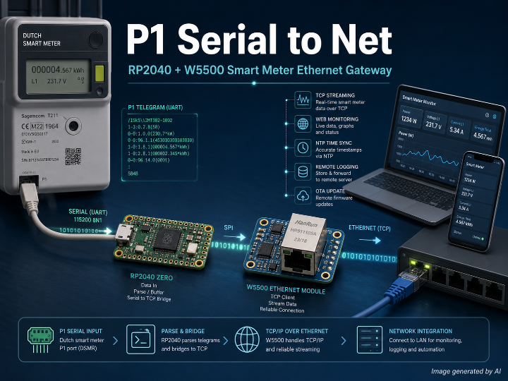
Project Overview
p1_serial_to_net is an embedded Serial-to-Ethernet gateway built with a Waveshare RP2040 Zero and a W5500 Lite Ethernet module. Its primary purpose is to receive P1 telegrams from a Dutch smart meter through UART and expose the data to Ethernet-connected applications through a TCP server. The firmware is implemented as a PlatformIO Arduino project using Arduino Ethernet 2.0.2.
The project goes beyond a minimal serial bridge. It includes a P1 TCP service, a separate remote log service, an HTTP status and monitoring interface, HTTP-based firmware update functions, NTP synchronization, DHCP configuration, and WS2812 status indication.
Technical Assessment
| Item | Assessment |
|---|---|
| Project Type | Embedded Serial-to-Ethernet gateway / smart-meter data bridge |
| MCU | Waveshare RP2040 Zero |
| Ethernet | W5500 Lite via SPI0 |
| P1 Interface | UART1, 115200 baud, 8N1 |
| Main TCP Service | Port 2000 |
| P1 Clients | Up to 3 simultaneous connections |
| Remote Logging | TCP port 2001, one client |
| HTTP Service | Port 80 |
| Address Configuration | DHCP |
| Wireless Network | Not implemented |
| Hybrid Network | No |
| WIZnet Product | W5500 Ethernet Controller |
| TOE | Assessment: Yes, through the W5500 hardwired TCP/IP stack via Arduino Ethernet library |
The MCU application does not directly manipulate W5500 socket registers. It uses EthernetServer, EthernetClient, EthernetUDP, Ethernet.begin() and related Arduino Ethernet APIs. The library subsequently operates the WIZnet hardware sockets. The W5500 itself implements TCP, UDP, IPv4 and related protocols in hardware and provides eight independent hardware sockets. Therefore, TOE usage is classified as library-mediated hardware TCP/IP offload rather than direct socket-register programming by the application.
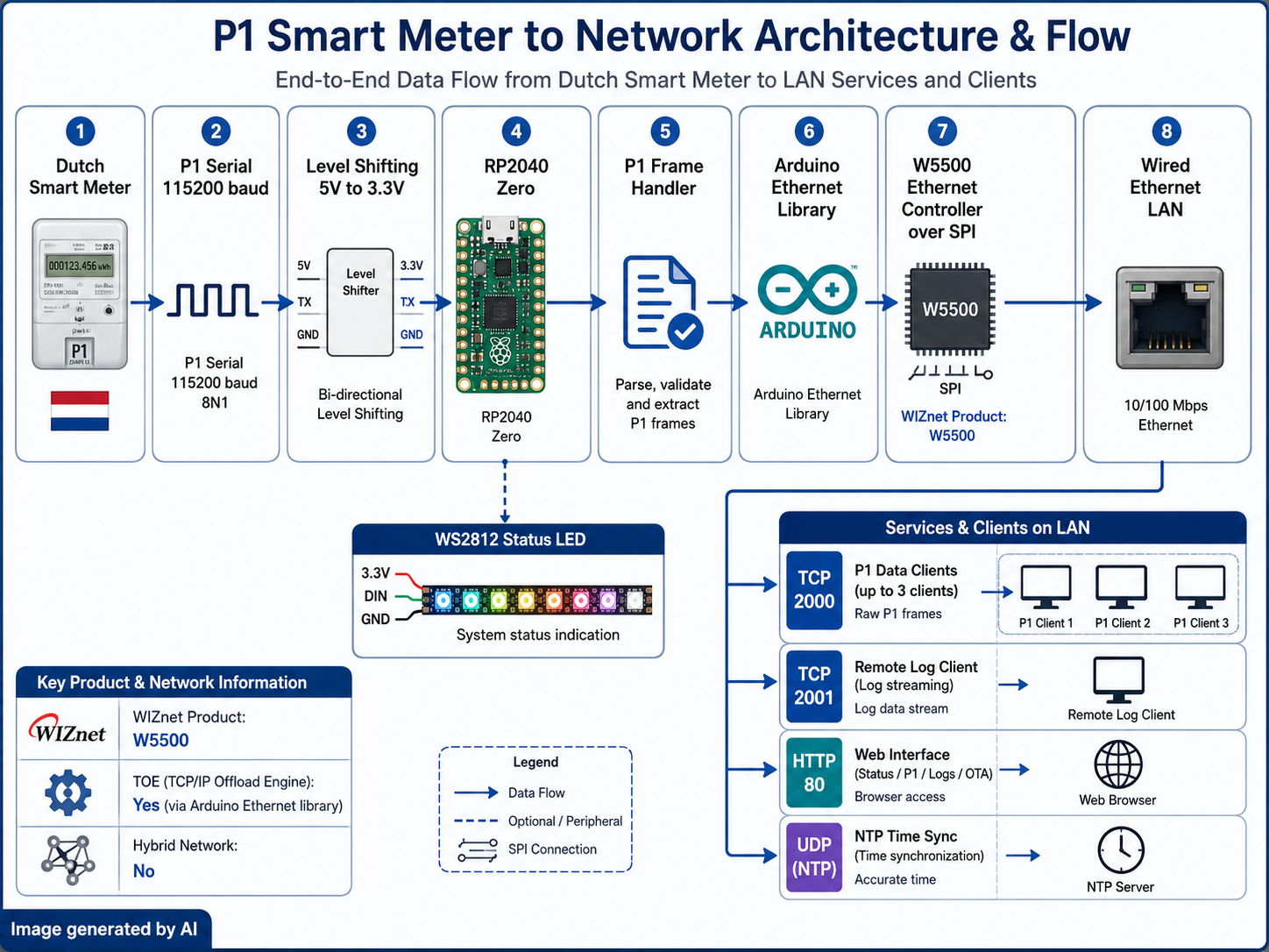
System Architecture
Dutch Smart Meter
      │
      │ P1 serial data
      │ 115200 baud
      ▼
P1 Port Pin 5
      │
      │ 5 V → 3.3 V level shifting
      ▼
RP2040 Zero
  UART1 RX : GPIO1
      │
      ▼
P1 Frame Handler
  '/' → telegram start
  '!' → telegram end
  + 4 checksum characters
      │
      ├─────────────► WS2812 Status LED
      │
      ▼
sendToAllClients()
      │
      ▼
Arduino Ethernet Library
      │
      │ SPI0
      ▼
W5500 Lite
      │
      ▼
Wired Ethernet LAN
      │
      ├─ TCP 2000 → P1 Client 1
      ├─ TCP 2000 → P1 Client 2
      ├─ TCP 2000 → P1 Client 3
      ├─ TCP 2001 → Remote Log Client
      ├─ HTTP 80  → Status / P1 / Logs / OTA
      └─ UDP      → NTP synchronization
The W5500 is connected through SPI0 using GPIO2 for SCK, GPIO3 for MOSI, GPIO4 for MISO and GPIO5 for chip select. GPIO6 controls W5500 reset and GPIO7 is assigned to the W5500 INT signal. The P1 data input uses GPIO1. Because the documented P1 data signal is 5 V while the RP2040 operates at 3.3 V, the repository explicitly requires a voltage divider or level-shifter circuit between the meter and MCU.
Operation Flow
- The firmware initializes the debug serial interface, LittleFS, NeoPixel status LED and W5500 network interface. The W5500 is reset, SPI is initialized, and DHCP is requested through
Ethernet.begin(mac). - TCP client management, the remote log server, the HTTP server and NTP synchronization are initialized before the P1 UART interface is started.
- UART1 receives P1 data at 115200 baud. The handler recognizes
/as the beginning of a telegram and!as its end marker, then collects the following four checksum characters and line termination characters. A 2048-byte buffer limit protects against unbounded message growth. - Once a complete telegram is assembled,
sendToAllClients()transmits the same telegram to every active P1 TCP client. The server allows three simultaneous P1 client slots and disconnects the oldest client if a new connection arrives while all slots are occupied. - The TCP client handler also contains a reverse path that reads incoming TCP data and writes it to
Serial1. However, the hardware documentation describes UART TX/GPIO0 as unused for the P1 connection, so the practical role of this reverse serial path is not fully defined by the repository.
Network and Management Services
The main data interface is a TCP server on port 2000. A separate TCP server on port 2001 provides remote firmware logs. The HTTP service on port 80 exposes information, P1 data, P1 streaming, logs, status pages and firmware upload functions through routes including /info, /p1, /p1/stream, /logs, /logs/stream, /status and /ota.
NTP uses a temporary EthernetUDP socket so that a hardware socket is not permanently consumed by time synchronization. The implementation opens UDP port 8888 locally, sends NTP requests to port 123 and releases the socket after completion.
WIZnet Product Role
WIZnet Product: W5500
The W5500 is the project's complete wired network interface rather than a secondary peripheral. The RP2040 sends network commands and payloads to the W5500 over SPI, while the W5500 provides the Ethernet MAC/PHY, hardware TCP/IP processing and hardware socket resources used by the TCP, HTTP, DHCP and UDP services.
The firmware explicitly budgets the W5500 socket resources across the P1 server, remote logging, HTTP/OTA and temporary NTP traffic. This is particularly relevant because the W5500 provides eight independent hardware sockets rather than an unrestricted software socket pool.
TOE Usage
TOE: Yes, library-mediated.
Assessment/inference: The project qualifies as TOE usage because TCP/UDP processing is performed through the W5500's hardwired TCP/IP implementation. The application itself uses the Arduino Ethernet abstraction rather than directly controlling Sn_MR, Sn_CR, socket interrupt registers or other W5500 registers.
Hybrid Network
Hybrid Network: No.
Only wired Ethernet networking is implemented. No Wi-Fi, cellular, LoRa or other wireless network stack is present in the PlatformIO configuration or application initialization path. The P1 UART link is a device-level serial interface and does not constitute a second network interface.
Strengths
- Clear hardware role separation: RP2040 handles P1 serial framing and application logic while W5500 provides Ethernet connectivity and hardware TCP/IP.
- Multi-client data distribution: one smart-meter stream can be delivered to up to three TCP clients.
- Operational visibility: NeoPixel status indication, remote TCP logging and HTTP status pages provide several diagnostic paths.
- Network maintenance functions: DHCP, NTP and HTTP-based OTA are integrated into the same embedded device.
- Practical electrical documentation: the repository explicitly documents the required 5 V-to-3.3 V level shifting on the P1 input.
Limitations and Code-Level Findings
P1 checksum validation is not actually implemented in the reviewed P1 handler. The code reads the four characters following !, but no CRC calculation or comparison occurs before the telegram is forwarded. Therefore the README description of “message validation” should be interpreted as frame assembly and boundary detection rather than verified DSMR checksum validation.
The repository attaches GPIO7 to an interrupt service routine and uses w5500InterruptFlag to trigger network processing. However, explicit W5500 socket/common interrupt-mask register configuration such as SIMR or Sn_IMR is not present in the reviewed network initialization code. The main loop also retains a periodic fallback path, so fully interrupt-driven W5500 operation is not established from the reviewed application code alone.
OTA access uses HTTP Basic authentication. The default username and password are stored in config.h as admin and update123, and the generated unauthorized page even displays these defaults. Because the service is plain HTTP rather than HTTPS, the default configuration is appropriate only for a controlled local network unless the credentials and network exposure are changed.
There is also a configuration inconsistency in NTP handling. config.h defines pool.ntp.org, while the implementation does not reference that macro and instead uses the fixed Google NTP address 216.239.35.0.
Application Value
The project provides a compact reference architecture for turning a legacy or appliance-oriented serial data source into an Ethernet-accessible service. Its strongest reusable element is not P1-specific parsing, but the integration of UART acquisition + W5500 hardware TCP/IP + multiple TCP consumers + embedded diagnostics and maintenance services on a small RP2040 platform.
This structure can be adapted to other serial telemetry systems where a device produces continuous UART data that must be consumed by several applications over a reliable wired LAN.
Author Information
Mark Hendriksen (hendriksen-mark) is based in the Netherlands. His GitHub profile identifies him as a technical specialist for personal cars at Zeekr EU and as a maintainer/support contributor for DiyHue. His public profile also shows work across Python, JavaScript and C++ projects related to DiyHue and connected-device software.
Final Summary
p1_serial_to_net is a practical RP2040-based smart-meter gateway in which the W5500 is a central system component rather than an incidental Ethernet adapter. It converts 115200-baud P1 serial telegrams into multi-client TCP streams while also supporting logging, HTTP monitoring, NTP and OTA functions. The project uses the W5500's hardwired TCP/IP capabilities through the Arduino Ethernet library, so it can be classified as a TOE-based wired Ethernet design, but not as a Hybrid Network implementation.
RP2040과 W5500을 이용한 P1 스마트미터 Serial-to-Ethernet 브리지
프로젝트 개요
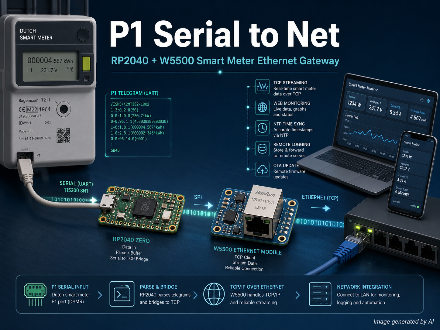
p1_serial_to_net은 Waveshare RP2040 Zero와 W5500 Lite를 조합한 임베디드 Serial-to-Ethernet 게이트웨이이다. 스마트미터의 P1 포트에서 UART로 수신한 데이터를 Ethernet의 TCP 스트림으로 변환하여 네트워크의 여러 클라이언트가 동시에 사용할 수 있도록 구성되어 있다. 개발 환경은 PlatformIO와 Arduino Framework이며, 네트워크 계층에는 Arduino Ethernet 2.0.2 라이브러리를 사용한다.
P1은 네덜란드 계열 스마트미터에서 계량 정보를 외부 장치로 제공하기 위한 직렬 인터페이스다. 이 프로젝트는 단순 UART-to-TCP 변환뿐 아니라 원격 로그, HTTP 상태 페이지, P1 웹 스트림, OTA 펌웨어 업데이트, DHCP, NTP, 상태 LED까지 하나의 RP2040/W5500 시스템에 통합한다.
기술 판단
| 항목 | 내용 |
| 프로젝트 유형 | 임베디드 Serial-to-Ethernet 게이트웨이 / 스마트미터 데이터 브리지 |
| MCU | Waveshare RP2040 Zero |
| Ethernet | W5500 Lite, SPI0 연결 |
| P1 통신 | UART1, 115200 baud, 8N1 |
| P1 TCP 서버 | Port 2000 |
| 동시 P1 클라이언트 | 최대 3개 |
| 원격 로그 | TCP Port 2001 |
| HTTP | Port 80 |
| IP 설정 | DHCP |
| WIZnet 제품 | W5500 Ethernet Controller |
| TOE | 사용으로 판단, Arduino Ethernet Library 경유 |
| Hybrid Network | 아님 |
시스템 구조
스마트미터
   │
   │ P1 Serial / 115200 baud
   ▼
P1 Pin 5
   │
   │ 5 V → 3.3 V Level Shifter
   ▼
RP2040 Zero
 UART1 RX / GPIO1
   │
   ▼
P1 Frame Handler
 '/' : 프레임 시작
 '!' : 프레임 종료
 + checksum 문자 4개
   │
   ├──────────► WS2812 상태 LED
   │
   ▼
sendToAllClients()
   │
   ▼
Arduino Ethernet Library
   │
   │ SPI0
   ▼
W5500 Lite
   │
   ▼
유선 Ethernet
   │
   ├─ TCP 2000 → P1 Client #1
   ├─ TCP 2000 → P1 Client #2
   ├─ TCP 2000 → P1 Client #3
   ├─ TCP 2001 → Remote Log
   ├─ HTTP 80  → Status / P1 / Logs / OTA
   └─ UDP      → NTP
W5500은 GPIO2 SCK, GPIO3 MOSI, GPIO4 MISO, GPIO5 CS로 구성된 SPI0에 연결된다. GPIO6은 W5500 Reset, GPIO7은 INT 신호에 사용된다. P1 데이터는 GPIO1의 UART1 RX로 입력된다. P1 데이터 신호가 5 V이고 RP2040 GPIO가 3.3 V이므로 저장소에서는 저항 분압이나 74LVC1T45, 74LV4050 등의 레벨 시프터 사용을 명시하고 있다.
동작 흐름
- 부팅 후 디버그 Serial, LittleFS, WS2812 상태 LED를 초기화한다. 이어 W5500을 Reset한 뒤 SPI와 Ethernet을 초기화하고
Ethernet.begin(mac)으로 DHCP 주소를 요청한다. - P1 TCP 클라이언트 관리, 원격 로그 서버, HTTP 서버와 NTP 기능을 초기화한 뒤 P1 UART를 시작한다.
- P1 데이터는 UART1에서 115200 baud, 8N1로 수신한다.
/문자를 Telegram 시작으로 인식하고!가 나타나면 뒤따르는 checksum 문자 4개와 CR/LF까지 버퍼에 저장한다. P1 버퍼 크기는 2048 byte로 제한되어 있다. - 하나의 Telegram이 완성되면
sendToAllClients()가 현재 연결된 모든 P1 TCP 클라이언트에 같은 데이터를 전송한다. 최대 3개의 클라이언트를 관리하며, 슬롯이 모두 사용 중일 때 새로운 클라이언트가 접속하면 가장 오래된 연결을 종료하고 새 연결을 수용한다. clients.cpp에는 TCP 클라이언트에서 수신한 데이터를 다시Serial1.write()로 전달하는 역방향 경로도 존재한다. 다만 저장소의 P1 배선 설명에서는 GPIO0/UART TX를 사용하지 않는 것으로 설명하므로, 이 역방향 기능의 실제 하드웨어 사용 방식은 명확하게 정의되어 있지 않다.
네트워크 서비스
핵심 P1 데이터는 TCP 2000번 포트로 제공되며 최대 세 클라이언트가 접속할 수 있다. 별도로 TCP 2001번 포트의 원격 로그 서버가 존재한다. HTTP 서버는 80번 포트를 사용하며 /info, /p1, /p1/stream, /logs, /logs/stream, /status, /ota 등의 경로를 처리한다.
NTP는 지속적으로 UDP 소켓을 점유하지 않고 동기화 시점에만 임시 EthernetUDP 객체를 생성한다. 로컬 UDP 8888번 포트를 사용해 NTP 123번 포트로 요청하고 동기화가 끝나면 소켓을 반환하는 구조다.
WIZnet 제품 사용 여부와 역할
W5500 Ethernet Controller
WIZnet Product Role: 유선 Ethernet 및 Hardwired TCP/IP 통신 경로 담당
W5500은 단순 보조 네트워크 모듈이 아니라 이 프로젝트의 모든 외부 네트워크 통신을 담당한다. RP2040과 SPI로 연결되고, Ethernet MAC/PHY와 TCP/IP 처리는 W5500 내부에서 수행된다. TCP 2000, TCP 2001, HTTP, DHCP와 UDP/NTP 통신이 모두 이 경로를 사용한다.
W5500은 하드웨어 TCP/IP 스택과 8개의 독립 Hardware Socket을 제공한다. 프로젝트 역시 P1 TCP, 로그, HTTP/OTA, NTP 등에 제한된 W5500 소켓 자원을 배분하는 구조를 갖고 있다.
TOE 사용 여부
TOE: 사용으로 판단
추론임: 저장소 자체에서 이를 “TOE”라는 용어로 정의하지는 않는다. 그러나 W5500의 Hardwired TCP/IP 기능을 이용하여 TCP와 UDP 처리를 하므로 WIZnet 관점에서는 TOE 활용 프로젝트로 분류할 수 있다.
애플리케이션 코드가 W5500의 Socket Register를 직접 제어하는 방식은 아니다.
Application
    ↓
EthernetServer / EthernetClient / EthernetUDP
    ↓
Arduino Ethernet Library
    ↓
W5500 Hardware Socket
    ↓
W5500 Hardwired TCP/IP
    ↓
Ethernet
즉, W5500 Socket Register 직접 제어형이 아니라 Arduino Ethernet Library를 통한 TOE 활용형이다. Arduino Ethernet 라이브러리 내부에서는 WIZnet 칩의 Hardware Socket 상태와 레지스터를 제어하여 TCP 서버와 클라이언트 기능을 제공한다.
Hybrid Network 여부
Hybrid Network: 해당 없음
이 프로젝트에서 네트워크 인터페이스는 W5500 기반 유선 Ethernet 하나뿐이다. Wi-Fi, BLE, Cellular, LoRa 등의 별도 무선 네트워크 인터페이스는 PlatformIO 설정과 애플리케이션 초기화 코드에서 확인되지 않는다.
스마트미터와 RP2040 사이의 P1 UART는 장치 간 Serial Interface이므로 유선 Ethernet과 함께 사용되더라도 Hybrid Network로 분류하지 않는다.
장점
- RP2040과 W5500의 역할이 명확하다. RP2040은 UART 데이터 처리와 애플리케이션 로직을 맡고 W5500은 Ethernet과 TCP/IP를 담당한다.
- 하나의 P1 데이터를 최대 3개의 TCP 클라이언트에 동시에 배포할 수 있다.
- 원격 로그, HTTP 상태 페이지, WS2812 LED를 함께 제공하여 동작 상태를 확인하기 쉽다.
- DHCP, NTP, HTTP OTA까지 포함해 독립적으로 운영 가능한 소형 Ethernet 장치 형태를 갖춘다.
- P1의 5 V 출력과 RP2040 3.3 V GPIO 사이의 레벨 변환 회로까지 구체적으로 문서화되어 있다.
한계 및 코드상 확인 사항
P1 checksum은 실제로 검증하지 않는다
README에서는 P1 message validation과 checksum 처리를 기능으로 소개하고 있지만, 실제 p1_handler.cpp는 ! 다음의 checksum 문자 네 개를 수집만 하고 CRC를 계산하거나 비교하지 않는다. 따라서 현재 구현은 P1 Telegram의 경계를 인식해 완성된 프레임을 전달하는 기능에 가깝고, 데이터 무결성을 검증하는 완전한 P1 parser로 보기는 어렵다.
또한 OBIS 항목 등의 계량 데이터를 개별 필드로 해석하는 구조도 확인되지 않는다. P1 Telegram 전체를 TCP로 전달한 뒤 실제 데이터 해석은 외부 클라이언트가 수행하는 구조에 가깝다.
W5500 INT 사용은 추가 검증이 필요하다
코드에서는 GPIO7에 W5500 INT 신호를 연결하고 MCU Interrupt Handler에서 w5500InterruptFlag를 설정한다. 메인 루프는 이 Flag가 설정되면 네트워크 처리를 수행한다.
다만 코드상 확인된 범위에서는 W5500의 SIMR, Sn_IMR 등 내부 Interrupt Mask Register를 설정하는 부분이 없다. 따라서 README에 적힌 “interrupt-driven network processing”이 W5500에서 실제로 활성화되는지는 저장소 코드만으로 확정하기 어렵다. 메인 루프에는 100 ms 주기의 fallback 처리도 함께 존재한다.
OTA 기본 설정의 보안 한계
OTA는 HTTP Basic Authentication을 사용하며 기본 계정이 admin / update123으로 소스에 직접 정의되어 있다. HTTP 서버 역시 TLS가 없는 일반 HTTP이므로 기본 상태에서는 인증 정보가 암호화되지 않는다.
특히 HTTP 401 응답 페이지에서도 해당 기본 계정 정보를 직접 표시하도록 구현되어 있어, 실제 운용 환경에서는 기본 설정을 그대로 사용하는 구조에 제약이 있다.
NTP 설정과 실제 구현이 다르다
config.h에는 NTP 서버가 pool.ntp.org로 설정되어 있지만 ntp_client.cpp에서는 해당 설정값을 사용하지 않고 time.google.com에 해당한다고 주석 처리된 216.239.35.0 주소를 직접 사용한다.
설정 파일과 실제 네트워크 동작 사이에 일부 구현 불일치가 존재하는 사례다.
적용 가치
이 프로젝트의 활용 가치는 P1 스마트미터 자체보다 Serial 장치를 Ethernet 서비스로 변환하는 임베디드 게이트웨이 구조에 있다.
Serial Sensor / Meter
        ↓
      UART
        ↓
      MCU
        ↓
W5500 Hardware TCP/IP
        ↓
   Wired Ethernet
        ↓
Multiple TCP Applications
UART로 지속적으로 데이터를 출력하는 계측기, 산업용 센서 또는 기존 Serial 장치를 네트워크에 연결하면서 여러 소비자가 동시에 데이터를 받아야 하는 시스템에 응용할 수 있다. 특히 MCU에서 전체 TCP/IP 소프트웨어 스택을 직접 운용하기보다 W5500 Hardware Socket을 이용하는 구조의 실제 예제로 활용 가치가 있다.
저자 정보
저자는 **Mark Hendriksen (hendriksen-mark)**이다. GitHub 프로필에는 네덜란드 기반으로 표시되어 있으며 Zeekr EU의 Personal Cars Technical Specialist이자 DiyHue의 Maintainer & Support 역할을 수행하는 것으로 소개되어 있다. 공개 저장소에서도 Python, JavaScript, C++ 기반의 DiyHue 및 연결형 디바이스 관련 활동을 확인할 수 있다.
-
p1_serial_to_net
