
Microcontroller-Based Encoder Signal Emulator for PLC Interface Testing
A configurable MCU platform simulates incremental and SSI encoder outputs, injects faults, and converts them into industrial differential signals for PLC test.
Overview
This patent describes a programmable encoder signal emulator for industrial automation testing. Instead of relying on a physical rotary encoder and a moving machine, the device computes a virtual shaft position in real time and turns that state into either incremental quadrature pulses or absolute serial encoder output. It is positioned as a test tool for PLC encoder interfaces during development, production-line validation, and field maintenance.
Main Content
The problem it addresses is practical and specific. Traditional PLC encoder-interface testing often depends on a real encoder and some physical motion source, which makes early integration work inconvenient, expensive, and limited in scenario coverage. The patent explicitly argues that existing pulse generators usually cover only incremental signals, while simple MCU circuits lack flexible configuration, realistic motion profiles, fault simulation, and direct compatibility with industrial differential interfaces.
The core idea is to replace the physical encoder with a software-defined virtual axis. A host system sends configuration commands that define signal type, coding rule, motion parameters, and fault-injection mode. The controller then computes the virtual axis position in real time and uses that result to generate either quadrature A/B/Z pulses or absolute serial data such as SSI. After that, the output is electrically isolated and converted into industrial differential signaling.
This matters because the design is not just a pulse source. It is a signal emulator tied to a motion model. That difference changes the role of the device: it is not merely producing waveforms, but reproducing what a control system expects from a rotating axis under defined speed, acceleration, reversal, and fault conditions.
The patent separates the hardware into four main blocks: a core control unit, a communication interface unit, a signal generation and output unit, and an electrical isolation and level-conversion unit. The core control unit runs the virtual-axis model and schedules signal generation. The communication block receives commands from the host. The signal block produces incremental and absolute encoder formats. The final electrical block isolates those signals and converts them into industrial differential outputs.
Within the signal generation block, the incremental path uses advanced timer resources to create 90-degree phase-shifted A and B pulses plus a Z reference pulse. The absolute path simulates encoder-side serial timing and outputs a digital position code representing the current absolute position. In the description, SSI is the concrete example, with the device acting like the encoder-side slave when the external master clock arrives.
The most important design choice is the virtual-axis computation loop. The patent places this calculation in a high-priority timer interrupt so that position is updated in real time from configured motion curves such as constant speed, constant acceleration, S-curve, or custom trajectories. That means the generated signal follows a motion model first and a waveform pattern second, which is why the device can emulate changing operating states instead of repeating a fixed canned output.
A second important choice is industrial output conditioning. The patent does not stop at TTL-style internal logic. It explicitly adds high-speed optocoupler isolation and RS422 differential driving so the generated signals can be sent with better noise resistance and connected more directly to PLC-class equipment. This is where the emulator becomes a practical field or factory tool rather than just a lab bench demonstration.
Fault injection is another major part of the design. The configuration includes modes for signal loss, pulse offset, jitter, or data errors, and the description even mentions simulating an open-circuit fault by disconnecting the signal path through relay control. This is a meaningful difference from a conventional signal generator, because the goal is not only to verify nominal decoding but also to expose the system’s diagnostic behavior and robustness limits.
System Context
In system terms, this device sits in the place normally occupied by a real encoder. Its job is not to replace the full machine, motor, and mechanics, but to replace the encoder-side feedback source so that the control system can be exercised without the real rotating hardware. That is why it is best understood as a support instrument inside a larger automation validation flow, not as the primary motion-control system itself.
If the virtual-axis model were removed, the device would lose much of its character and collapse toward a configurable waveform generator. If the electrical isolation and differential conversion were removed, it would still produce logic-level signals, but it would no longer match the intended industrial integration role nearly as well.
Architecture / Design Considerations
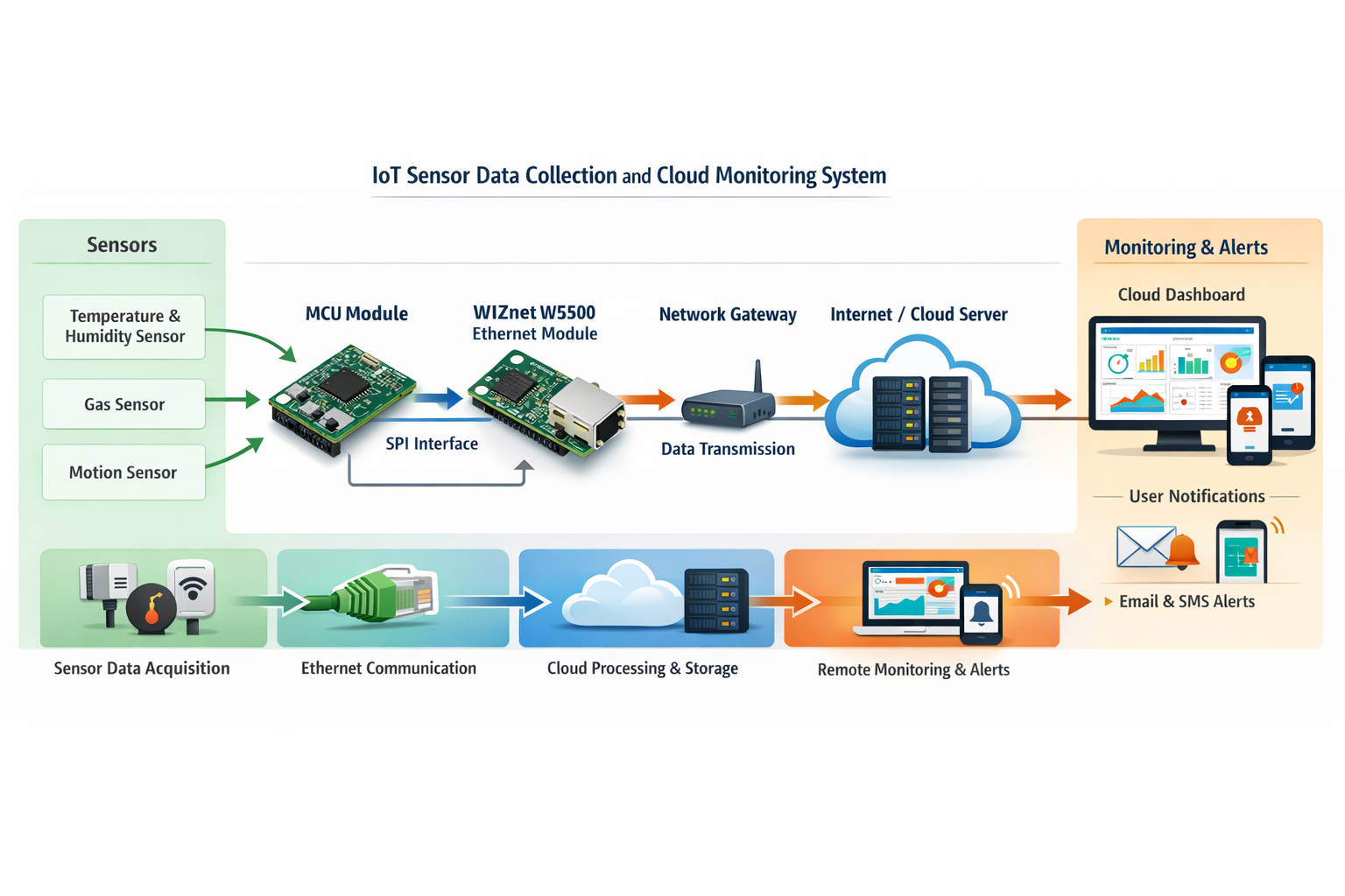
The patent supports USB, Ethernet, RS232, and RS485 as communication options, but Ethernet is not the center of the invention by itself. Its role is to let a host computer configure and supervise the emulator as part of a broader test setup.
In the concrete embodiment, the Ethernet interface is implemented with a WIZnet W5500 hardware TCP/IP chip. The patent does not make W5500 a mandatory claim element, but it does show W5500 as the named Ethernet choice in the implementation example. That matters because it places a real WIZnet Ethernet product inside the system as the network-facing configuration path rather than as the timing-critical signal-generation core.
The likely design reason is straightforward: the control core must preserve timing discipline for virtual-axis updates and encoder-signal output, while Ethernet connectivity is a support function for configuration and monitoring. Using a hardware TCP/IP Ethernet device such as W5500 fits that separation of roles by keeping network handling off the main control path. This interpretation follows the embodiment and the division of functions described in the patent.
The highest-cost failure zone in this architecture is the boundary between virtual-axis computation and deterministic signal emission. If position updates drift, stall, or desynchronize from timer-driven output, the generated encoder feedback stops representing a coherent motion state, and downstream PLC validation can become misleading even when the electrical signal still looks clean.
Possible Implications
This design is useful where teams need one portable platform to emulate multiple encoder styles, motion states, and fault conditions without carrying real motors, couplings, and encoders into every test stage. It can shorten integration work and make negative-case testing more repeatable.
At the same time, the patent stays within a clear boundary. It validates the control system’s encoder-facing input path, but it does not recreate the full physics of a real mechanical load, backlash, vibration, or analog sensor imperfection unless such effects are deliberately abstracted into the virtual model. That boundary is important when interpreting test results.
Conclusion
The technical value of this patent is not that it generates pulses. Plenty of devices can do that. Its real value is the combination of a virtual motion model, multi-format encoder emulation, industrial-grade output conditioning, and configurable fault injection in one test-oriented architecture. That combination shifts the device from being a generic signal source to being a practical encoder-side validation platform for PLC and industrial automation systems.
KR - Internal / Presentation
전체 개요
이 특허는 실제 회전 엔코더를 연결하지 않고도, PLC나 산업 자동화 제어기가 받는 엔코더 입력을 시험할 수 있도록 만든 엔코더 신호 시뮬레이터에 관한 것입니다. 공개 문서 기준으로 장치는 가상축 위치를 계산하고, 그 계산 결과를 증분형 A/B/Z 펄스나 절대형 SSI 같은 신호로 바꾼 뒤, 절연과 차동 변환을 거쳐 산업 장비가 받을 수 있는 형태로 출력하도록 설계되어 있습니다.
핵심은 “파형을 만드는 장치”가 아니라 “축의 상태를 계산해서 엔코더처럼 보이게 만드는 장치”라는 점입니다. 이 차이 때문에 이 장비는 단순 신호발생기보다 테스트 장비에 더 가깝고, 실제 제어기 검증 단계에서 더 직접적인 의미를 가집니다. 이는 특허 본문에 적힌 가상축 모델, 실시간 위치 계산, 증분/절대 신호 생성 흐름을 기준으로 한 해석입니다. 추론임.
문제의식과 기술적 맥락 재구성
특허가 직접 제기하는 문제는 분명합니다. 기존 PLC 엔코더 입력 시험은 실제 엔코더와 물리적인 회전 장치를 요구하는 경우가 많아서, 초기 통합 단계에서는 번거롭고 비용이 들며, 조건을 다양하게 바꾸어 보기 어렵다고 설명합니다. 또한 시중의 일반 펄스발생기는 주로 증분형만 다루고, 단순 MCU 회로는 설정성, 고장 주입, 산업용 차동 인터페이스 적합성에서 한계가 있다고 적고 있습니다.
이 문제의식은 산업 자동화 시험 장비 관점에서 꽤 현실적입니다. 제어기 쪽에서는 “입력 포트가 정상인가”만 보는 것이 아니라, 속도 변화, 방향 반전, 이상 신호, 타이밍 어긋남 같은 상황에서 얼마나 안정적으로 동작하는지가 중요하기 때문입니다. 그래서 이 특허는 실제 엔코더를 대체하는 것이 목적이 아니라, 실제 엔코더가 연결되었을 때 제어기가 보게 될 피드백 조건을 통제 가능한 방식으로 재현하는 것을 목표로 잡고 있다고 보시면 됩니다. 두 번째 문장은 기술적 목적을 재구성한 설명이며, 추론임입니다.
기존 접근 대비 핵심 차이는 여기 있습니다. 일반 펄스발생기는 보통 “정해진 파형을 얼마나 정확히 내보내는가”에 가까운데, 이 특허는 “가상축의 운동 상태를 먼저 만들고 그 상태를 엔코더 형식으로 변환하는가”에 초점을 둡니다. 즉, 파형 중심이 아니라 운동 상태 모델 중심입니다.
기술 흐름 설명
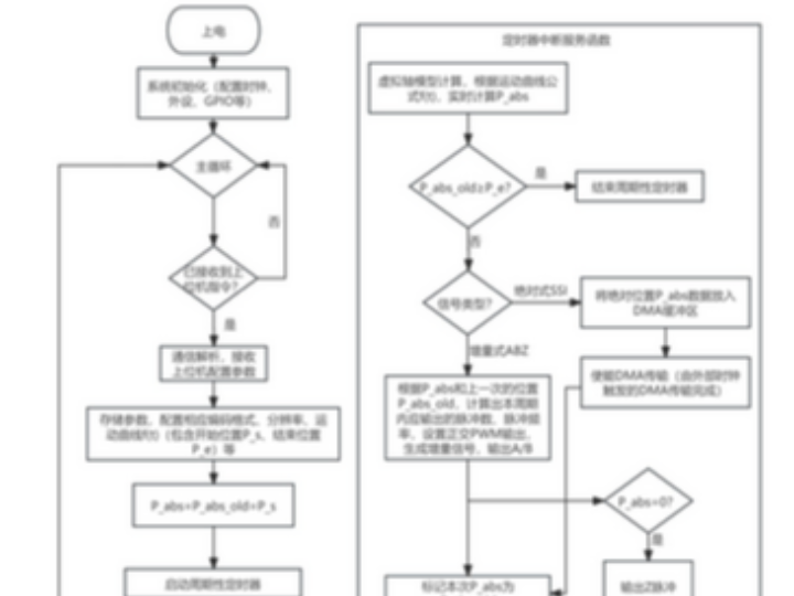
동작 순서는 특허 문서에 거의 그대로 나와 있습니다. 먼저 상위 장치가 통신 인터페이스를 통해 설정 명령을 보냅니다. 이 설정에는 신호 종류, 코딩 규칙, 운동 파라미터, 고장 주입 모드가 포함될 수 있습니다.
그 다음 핵심 제어부는 고우선순위 타이머 인터럽트에서 가상축의 절대 위치를 실시간으로 계산합니다. 문서에는 등속, 등가속, S-curve, 사용자 정의 위치 궤적 같은 운동 곡선이 언급되어 있고, 실시예에서는 1ms 주기로 위치를 갱신하는 구조가 제시됩니다.
그 뒤 신호 생성부가 현재 가상축 위치와 선택된 신호 타입에 따라 출력을 만듭니다. 증분형이면 A/B 90도 위상차 펄스와 Z 펄스를 만들고, 절대형이면 SSI 같은 직렬 위치 데이터를 내보냅니다. SSI 예시에서는 외부 PLC가 마스터 클럭을 주고, 이 장치가 슬레이브처럼 현재 절대위치를 비트열로 응답하는 식입니다.
마지막으로 전기 절연 및 레벨 변환부가 내부 논리 신호를 산업용 차동 신호로 바꿉니다. 특허는 고속 광커플러와 RS422 차동 드라이버를 명시하고 있으며, 이 덕분에 PLC 같은 산업 장비에 더 직접적으로 연결할 수 있는 형태를 지향합니다.
정리하면 흐름은 설정 수신 → 가상 위치 계산 → 엔코더 형식 변환 → 절연/차동 출력입니다. 이 네 단계가 단순해 보이지만, 실제 의미는 “운동 모델, 신호 형식, 산업 인터페이스”를 한 장치 안에서 이어붙였다는 데 있습니다. 두 번째 문장은 구조적 의미를 해석한 설명이며, 추론임입니다.
왜 이런 구조가 나왔는지에 대한 해설
이 구조가 나온 이유는 시험 대상이 PLC나 자동화 제어기의 엔코더 입력부이기 때문이라고 보는 것이 자연스럽습니다. 입력부를 검증하려면 실제 기계 시스템 전체를 재현할 필요는 없지만, 엔코더가 주는 피드백 형식과 타이밍은 어느 정도 사실적으로 재현해야 합니다. 그래서 이 특허는 모터 제어나 기계 구동을 직접 구현하지 않고, 피드백 소스에 해당하는 엔코더 쪽만 가상화한 것으로 읽힙니다. 마지막 문장은 구조 선택 배경에 대한 해석이며, 추론임입니다.
또 하나의 이유는 시험의 반복성과 조건 제어입니다. 실제 엔코더를 손으로 돌리거나 별도 구동계를 붙이면 재현성이 떨어질 수 있는데, 가상축 기반 구조는 같은 조건을 다시 만들어 내기가 쉽습니다. 이는 생산라인 테스트나 현장 유지보수에서 꽤 큰 장점이 됩니다.
보조 수단으로서의 위치도 여기서 분명해집니다. 이 장치는 실제 공정 제어 시스템의 주연이 아니라, 그 시스템이 입력을 제대로 해석하는지 검증해 주는 검증용 보조 장비입니다. 다시 말해 제어기 자신을 대신하는 장치가 아니라, 제어기가 의존하는 피드백 채널을 대신 연기하는 장치입니다. 두 번째 문장은 역할 경계를 정리한 해석이며, 추론임입니다.
설계 선택의 배경, 제약 조건, 대안 가능성
가장 눈에 띄는 설계 선택은 가상축 계산을 고우선순위 인터럽트에 둔 점입니다. 이는 위치 계산과 신호 생성 사이의 시간 일관성을 지키려는 선택으로 읽힙니다. 만약 이 계산이 통신 처리나 화면 갱신 같은 비결정적 작업과 섞이면, 출력 파형은 멀쩡해 보여도 실제 의미상 틀린 위치 정보를 반영할 수 있습니다. 마지막 문장은 설계 리스크에 대한 해석이며, 추론임입니다.
가장 실패 비용이 큰 판단 지점도 바로 여기입니다. 가상축 절대위치 계산과 실제 신호 방출의 동기성이 무너지면, PLC가 받은 데이터는 전기적으로는 정상처럼 보여도 의미적으로는 잘못된 피드백이 됩니다. 시험 장비가 틀리면 시험 결과 전체가 오염되기 때문에, 이 구간의 실패 비용이 가장 큽니다. 이는 특허의 인터럽트 기반 위치 계산과 하드웨어 기반 신호 출력 구조를 근거로 한 분석이며, 추론임입니다.
절연과 RS422 차동 출력도 중요한 선택입니다. 이 부분을 빼면 내부 로직 수준에서는 여전히 신호를 만들 수 있겠지만, 산업 장비에 직접 연결하는 실용성은 크게 떨어집니다. 즉, 이 특허는 “신호를 만들 수 있는가”보다 “산업 현장에서 받아들여질 수 있는 형태인가”까지 포함해 설계하고 있습니다. 마지막 문장은 선택 이유를 정리한 해석이며, 추론임입니다.
대안도 생각해 볼 수 있습니다. 문서 자체가 MCU 외에 FPGA 구현 가능성을 실시예 설명에서 언급하므로, 더 높은 병렬성이나 더 높은 출력 속도가 필요하면 FPGA 쪽으로 무게를 옮길 수 있습니다. 다만 현재 청구항 중심은 MCU 기반 장치이므로, FPGA 구현이 같은 강도로 권리범위를 대표한다고 단정하는 것은 조심해야 합니다. 두 번째 문장은 청구항과 실시예의 관계에 대한 해석이며, 추론임입니다.
생소한 개념에 대한 풀어쓴 설명
“증분형 엔코더”는 현재 절대 위치를 숫자로 보내는 방식이 아니라, 얼마나 움직였는지를 펄스로 알려주는 방식이라고 이해하시면 됩니다. A상과 B상 두 펄스의 위상차를 보면 방향을 알 수 있고, Z펄스는 한 바퀴에 한 번 나오는 기준점 역할을 합니다.
“절대형 엔코더”는 반대로 현재 위치 자체를 코드 값으로 알려주는 방식입니다. 이 특허에서는 SSI가 예시로 제시되며, 외부 마스터 클럭에 맞추어 현재 위치 비트열을 차례대로 내보내는 구조가 설명됩니다.
“가상축 모델”은 실제 축이 돌고 있지 않아도, 소프트웨어 안에서 축의 위치와 속도를 계산해 그 결과를 진짜 축처럼 다루는 개념입니다. 이 특허에서는 그 가상 위치가 엔코더 신호의 원천 데이터가 됩니다.
시스템 구성 및 선택지 해석
통신 인터페이스는 USB, Ethernet, RS232, RS485를 지원할 수 있게 열어 두고 있습니다. 중요한 점은 이 통신 경로가 엔코더 신호의 본체가 아니라 설정과 감시를 위한 상위 연동 경로라는 점입니다.
실시예 1에서는 Ethernet 인터페이스로 WIZnet W5500이 명시되어 있습니다. 문서상 W5500은 독립 청구항의 필수 요소는 아니지만, 실제 구현 예에서는 네트워크 측 구성을 담당하는 구체 부품으로 배치되어 있습니다.
이 배치는 의미가 있습니다. 가상축 계산과 엔코더 신호 출력은 타이밍 민감도가 매우 높기 때문에, 네트워크 처리는 가능하면 보조 경로로 분리하는 편이 설계상 유리합니다. W5500 같은 하드웨어 TCP/IP 칩을 둔 것은 MCU가 시간 민감한 축 계산과 신호 생성에 더 집중하도록 하려는 구조로 읽는 것이 자연스럽습니다. 이 문장은 실시예의 부품 선택과 기능 분리를 바탕으로 한 해석이며, 추론임입니다.
특정 구성요소를 제거했을 때 시스템 성격이 어떻게 바뀌는지도 분명합니다. 가상축 모델이 빠지면 이 장치는 운동 기반 엔코더 시뮬레이터라기보다 단순 파형 발생기에 가까워집니다. 반대로 절연/차동 출력이 빠지면 시뮬레이션 능력은 남아도 산업 현장 적합성이 크게 떨어집니다. 이 문장은 구성요소 제거에 따른 성격 변화를 정리한 해석이며, 추론임입니다.
내부 관점에서의 시사점
내부 검토 관점에서 보면, 이 특허의 진짜 포인트는 “한 장비로 여러 엔코더 규격을 흉내 낸다”보다도 운동 모델, 프로토콜 변환, 산업 인터페이스, 고장 주입을 한 흐름에 엮었다는 데 있습니다. 그래서 장비의 가치는 파형 정확도 단독이 아니라, 제어기 검증 시나리오를 얼마나 폭넓게 재현하느냐에 달려 있습니다. 두 번째 문장은 핵심 가치에 대한 재정리이며, 추론임입니다.
또한 이 특허는 실제 엔코더를 완전히 대체하는 기술이라기보다, 실제 엔코더를 쓰기 전에 제어기 입력 경로를 먼저 검증하는 전단계 장비로 이해하는 편이 안전합니다. 만약 발표나 문서화 시 이 경계를 흐리면, 기계계 오차나 실제 센서 비이상성까지 모두 재현하는 것처럼 오해될 수 있습니다. 두 번째 문장은 적용 경계에 대한 해석이며, 추론임입니다.
FAQ
1) 기존 펄스발생기와 가장 큰 차이는 무엇인가요?
가장 큰 차이는 이 장치가 단순히 파형만 내보내는 것이 아니라, 가상축 위치를 계산한 뒤 그 상태를 엔코더 신호로 변환한다는 점입니다. 그래서 등가속, S-curve, 고장 주입 같은 시험 시나리오를 더 자연스럽게 구성할 수 있습니다. 이는 특허 본문이 설명하는 가상축 계산과 증분/절대 신호 생성 구조를 바탕으로 한 정리입니다.
2) 왜 증분형과 절대형을 한 장치에 같이 넣었을까요?
PLC나 자동화 시스템은 현장마다 피드백 방식이 다르기 때문에, 시험 장비도 여러 인터페이스를 한 플랫폼에서 다루는 편이 실용적입니다. 특허가 말하는 “단일 하드웨어 플랫폼 + 가변 소프트웨어” 방향은 바로 이 범용성 확보를 노린 것으로 보입니다. 마지막 문장은 설계 의도에 대한 재해석이며, 추론임입니다.
3) 이 시스템에서 통신 인터페이스, 특히 Ethernet의 역할은 무엇인가요?
통신 인터페이스는 엔코더 신호 자체를 전송하는 주 경로라기보다, 상위 장치가 시험 조건을 설정하고 상태를 감시하는 관리 경로입니다. 실시예에서는 Ethernet용으로 WIZnet W5500이 들어가며, 이는 네트워크 처리를 보조 경로로 분리하는 설계와 잘 맞습니다. 두 번째 문장은 부품 역할에 대한 해석이며, 추론임입니다.
4) 실패 비용이 가장 큰 구간은 어디인가요?
가장 위험한 구간은 가상축 위치 계산 결과가 실제 신호 출력 타이밍과 어긋나는 순간입니다. 이 경우 전기적 신호는 정상처럼 보여도 의미적으로 틀린 엔코더 피드백이 되고, 결국 시험 대상 PLC보다 시험 장비 쪽이 더 큰 오류 원인이 될 수 있습니다. 이 평가는 문서의 인터럽트 기반 위치 계산과 하드웨어 신호 생성 구성을 근거로 한 분석이며, 추론임입니다.
5) 왜 이 장비를 보조 수단이라고 보아야 하나요?
이 장비는 모터, 기구부, 부하 특성 전체를 대신하지 않습니다. 대신 제어기가 받는 엔코더 피드백 입력만 통제 가능하게 재현하므로, 전체 시스템의 주역이라기보다 검증용 보조 장비로 이해하는 편이 정확합니다. 두 번째 문장은 시스템 내 역할 경계를 정리한 해석이며, 추론임입니다.
6) 특정 구성요소를 빼면 시스템 성격이 어떻게 달라지나요?
가상축 모델이 빠지면 이 장치는 운동 기반 시뮬레이터가 아니라 고급 펄스발생기 쪽에 가까워집니다. 반대로 절연과 RS422 차동 출력이 빠지면 테스트 기능은 남아도 산업 현장 연결성을 크게 잃게 됩니다. 이 설명은 특허의 각 블록 역할을 기준으로 재구성한 것이며, 추론임입니다.
저자 정보
공개 특허 문서에는 발명자로 杨义强, 曹仲禹가 표기되어 있으며, 출원인으로는 Changsha Ketuo Electric Co ltd가 기재되어 있습니다. 따라서 개인 발명자 정보보다 기업 출원 정보가 더 명확하게 공개된 사례로 보입니다.
다만 공개 문서만으로는 발명자 개인의 상세 경력, 세부 전공, 이전 연구 이력까지는 확인되지 않습니다. 따라서 개인 배경에 대해서는 공개된 정보가 제한적임이라고 보는 것이 안전합니다.
출원인은 특허 문서상 기업으로 표시되어 있고, 기술 내용도 산업 자동화 테스트 및 제어 인터페이스 맥락에 놓여 있으므로, 산업용 제어/전기 시스템 성격의 조직일 가능성이 높아 보입니다.