


IndustrialSimulator: ESP32-WROOM32 and W5500 Modbus TCP Process Simulator
An ESP-IDF firmware that turns an ESP32-WROOM32 with a W5500 into a deterministic industrial process simulator served over Modbus TCP on port 502.
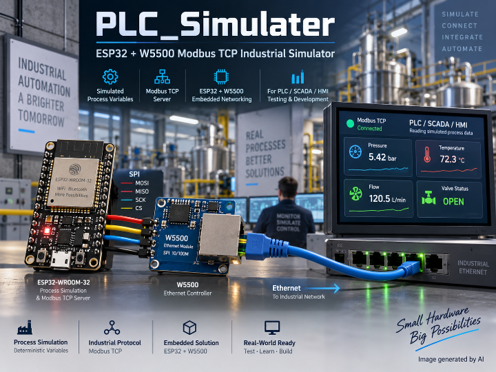

WIZnet - W5500
x 1

https://github.com/Luciferthedevil666/PLC_Simulater
Overview
IndustrialSimulator is an ESP-IDF firmware project for an ESP32-WROOM32 paired with a WIZnet W5500 Ethernet controller. It exposes deterministic industrial process variables through a Modbus TCP server, and it is organized as a set of reusable ESP-IDF components rather than as a single demo application. The purpose is narrow and useful: give SCADA screens, HMI panels, historians, and PLC-facing test scripts a fixed Ethernet endpoint that answers Modbus requests with values that behave like a plant, without a plant being present.
Because those values come from ramps, triangle waves, lag-like evolution, bounded drift, and seeded noise rather than from a free-running random source, two runs of the same profile produce the same curve. That determinism is what turns the board from a demo into a test fixture. The published tree pins a default network identity of 192.168.0.50 with gateway 192.168.0.1, subnet 255.255.255.0, and Modbus TCP port 502, so a client can be aimed at the board once and left alone across reflashes.
The repository is Luciferthedevil666/PLC_Simulater, default branch main, most recently pushed on 2026-07-18. Its own Notes section is candid about maturity: the componentized firmware foundation and the Modbus and process core work, while hardware validation on the target board is still required for W5500 socket-buffer behavior and for long-duration performance measurement. This writeup describes what the published source states, and marks the parts the author has flagged as not yet validated.
Hardware & Software Configuration
The bill of materials is deliberately short. An ESP32-WROOM32 module provides the application processor, a W5500 Ethernet controller sits on the SPI bus and provides wired networking, a USB UART carries logging and flashing, and 5 V USB supplies power. There is no display, no expansion board, and no analog front end, because every process value in this design is computed rather than measured.
Network identity is static by construction. The defaults are IP address 192.168.0.50, gateway 192.168.0.1, subnet mask 255.255.255.0, and Modbus TCP port 502. The README is explicit that the Ethernet identity is forced static at startup after the NVS configuration is loaded, and it gives the reason: this prevents an older saved configuration from moving the simulator back to a different subnet. On a bench where one board is shared, reflashed, and moved between networks, that single rule is the difference between "the simulator is at .50" and an afternoon of ARP scanning.
Pin assignments are centralized in components/bsp/src/industrial_bsp.c rather than scattered across drivers.
W5500 CS    GPIO5     SPI MISO   GPIO19
W5500 RST   GPIO4     SPI MOSI   GPIO23
W5500 INT   GPIO34    SPI SCLK   GPIO18
Status LED  GPIO2
The header components/bsp/include/industrial_bsp.h describes itself as the board support package for ESP32-WROOM32 plus W5500 wiring, and its pin enumeration begins with INDUSTRIAL_BSP_PIN_W5500_CS followed by INDUSTRIAL_BSP_PIN_W5500_RST. Consumers resolve pins through that enumeration instead of embedding numbers: components/spi/src/industrial_spi.c sets its .spics_io_num field from industrial_bsp_get_gpio(INDUSTRIAL_BSP_PIN_W5500_CS), so moving the chip select to a different GPIO is a one-line edit in the board layer rather than a search across the tree.
On the software side the project is a standard ESP-IDF build with no external build system. Install ESP-IDF, select the ESP32 target, and build:
idf.py set-target esp32
idf.py build
Then flash the board and watch the log over the USB UART:
idf.py flash monitor
Additional photos are available in the original repository: https://github.com/Luciferthedevil666/PLC_Simulater
System Architecture
Startup is explicitly ordered, and the order is the architecture. main/app_main.c brings modules up in dependency sequence: (1) logger, (2) NVS storage and configuration, (3) BSP, (4) SPI, (5) register database, (6) process simulator, (7) W5500 Ethernet manager, (8) Modbus TCP server, (9) diagnostics, (10) watchdog, and (11) the FreeRTOS runtime tasks. Nothing that touches the wire starts before the pin map and the SPI bus exist, and the register database exists before anything can serve a read from it.
The same shape is stated twice more in the tree. docs/ARCHITECTURE.md draws the chain as bsp -> spi -> w5500 -> ethernet -> network, and says plainly that W5500 owns Ethernet controller registers and socket commands. The CMake files then enforce it: components/w5500 registers with REQUIRES common bsp spi, components/ethernet with REQUIRES common w5500, and components/tcp with REQUIRES common w5500 modbus. A layering rule that lives only in a document tends to rot; a layering rule that also lives in idf_component_register fails the build when someone reaches across it.
The Modbus component implements MBAP parsing and response generation from scratch, and supports function code 03 read holding registers, 04 read input registers, 06 write single holding register, and 16 write multiple holding registers. The register database provides 1000 holding registers and 500 input registers, which is enough address space to lay out a plausible plant map rather than a handful of demo tags.
The process simulator is what makes those registers worth reading. It generates deterministic values using ramps, triangle waves, lag-like evolution, bounded drift, and seeded noise, and it ships profiles for normal operation, startup, shutdown, emergency stop, sensor failure, high temperature, low pressure, pump failure, valve failure, power failure, and maintenance mode. The failure profiles are the part worth borrowing: an emergency stop, a stuck valve, or a dead sensor is exactly the state an alarm rule or an operator screen is hardest to exercise against real equipment, and here it is a profile selection.
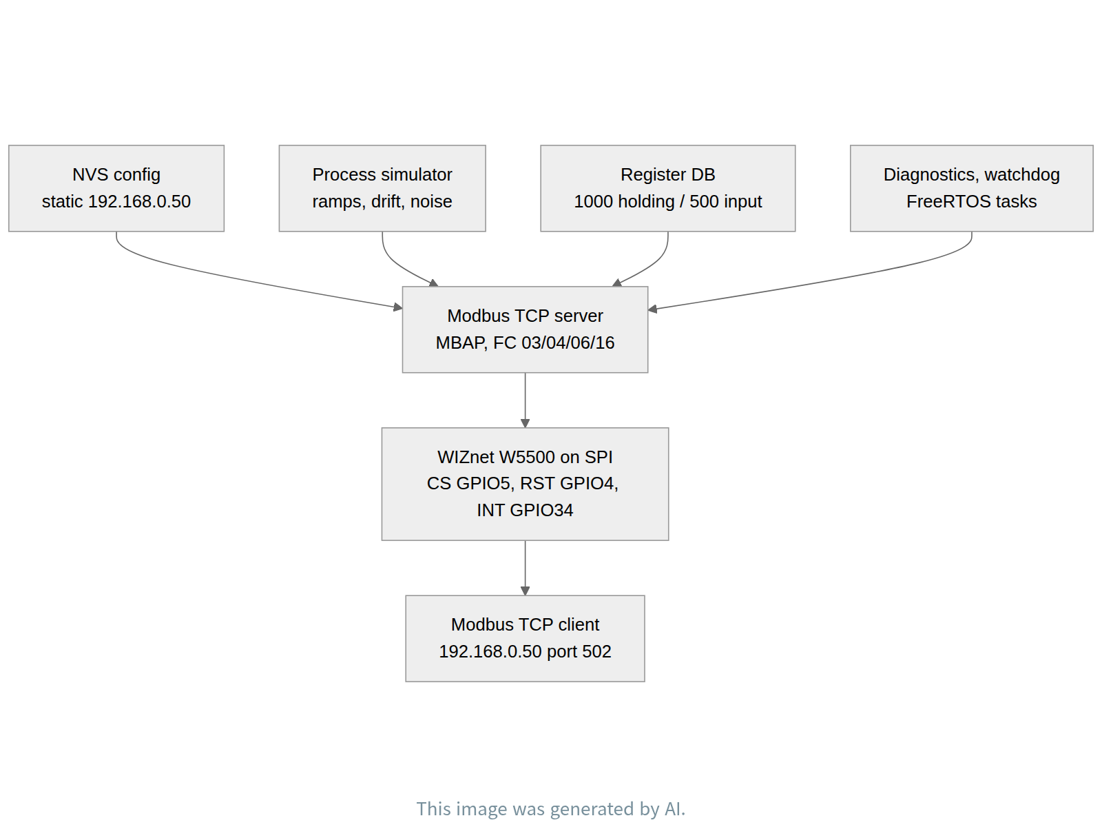
flowchart TB
  NVS["NVS config<br/>static 192.168.0.50"] --> MB
  SIM["Process simulator<br/>ramps, drift, noise"] --> MB
  REG["Register DB<br/>1000 holding / 500 input"] --> MB
  DIAG["Diagnostics, watchdog<br/>FreeRTOS tasks"] --> MB
  MB["Modbus TCP server<br/>MBAP, FC 03/04/06/16"] --> ETH
  ETH["WIZnet W5500 on SPI<br/>CS GPIO5, RST GPIO4, INT GPIO34"] --> CLI
  CLI["Modbus TCP client<br/>192.168.0.50 port 502"]
Role of the WIZnet W5500
The W5500 is not a peripheral bolted on at the end of this design; it is the layer everything above it is written against. components/w5500/include/industrial_w5500.h describes itself as a low-level W5500 register and socket driver, and the implementation in components/w5500/src/industrial_w5500.c works at register granularity, defining W5500_COMMON_BLOCK as 0x00 and W5500_VERSIONR as 0x0039 — the common register block select and the chip version register a driver reads first to prove the SPI link is real. tests/README.md lists W5500 version detection among its checks, which is the same idea expressed as a test rather than as a comment.
Board control is kept separate from protocol logic. components/bsp/src/industrial_bsp.c exposes industrial_bsp_reset_w5500(), so the hardware reset pulse on GPIO4 belongs to the board layer while the driver stays about registers. Above the driver, components/ethernet/src/industrial_ethernet.c includes industrial_w5500.h and calls industrial_w5500_init(&s_eth.mac, &s_eth.ip, &s_eth.gateway, &s_eth.subnet) to program the identity, then industrial_w5500_is_link_up(&s_eth.link_up) to publish carrier state upward to the rest of the firmware.
The most telling calls are in the TCP layer. components/tcp/src/industrial_tcp_server.c iterates over a socket range and calls industrial_w5500_socket_open_tcp((uint8_t)(TCP_SOCKET_BASE + i), s_config.listen_port) to place each socket in TCP mode on the listen port, and industrial_w5500_socket_close((uint8_t)(TCP_SOCKET_BASE + i)) to tear it down. Those are the W5500's own numbered hardware sockets, not descriptors handed out by a host stack: connection state, buffering, and the handshake live inside the controller, and the ESP32 spends its cycles on the process model and on Modbus framing instead. The header components/tcp/include/industrial_tcp_server.h states the intent directly, calling itself a TCP server abstraction isolating application protocols from W5500, so the Modbus code above it never sees a register write.
One caveat belongs here rather than in a footnote. The README states that hardware validation on the target board is still required for W5500 socket-buffer behavior and for long-duration performance measurements. The socket wiring is written and reviewable in source; what has not been signed off is how the multi-socket buffers behave under sustained polling from several clients, which is precisely the load a simulator attracts once a team points its tools at it.
FAQ
Do I need real process hardware to run this? No. Every value served over Modbus is produced by the process simulator inside the firmware. The only hardware needed is an ESP32-WROOM32, a W5500 module on SPI, a USB cable for power and logging, and an Ethernet link to the client.
Which Modbus functions are supported? Function code 03 read holding registers, 04 read input registers, 06 write single holding register, and 16 write multiple holding registers. MBAP parsing and response generation are implemented from scratch in the Modbus component, and the register database provides 1000 holding registers and 500 input registers on the default port 502.
Can I change the IP address? The defaults are 192.168.0.50 with gateway 192.168.0.1 and subnet 255.255.255.0, and the Ethernet identity is forced static at startup after NVS configuration is loaded, specifically so a stale saved configuration cannot relocate the board to another subnet. The README documents the defaults and that startup rule but not a provisioning interface, so treat the address as build and NVS configuration rather than as something a client can renegotiate over the wire.
Which pins does the W5500 use? Chip select on GPIO5, reset on GPIO4, interrupt on GPIO34, with the SPI bus on SCLK GPIO18, MOSI GPIO23, and MISO GPIO19, plus a status LED on GPIO2. All of them are defined once in the board support package and read back through industrial_bsp_get_gpio().
How finished is the firmware? The author's own Notes call it a componentized firmware foundation with a working Modbus and process core, and state that hardware validation on the target board is still required for W5500 socket-buffer behavior and long-duration performance measurements. Treat the Modbus and simulation layers as usable and the sustained-load characteristics as unmeasured.
What are the reuse terms? The repository record used for this writeup carries no license metadata, so anyone planning to reuse the code beyond reading it should ask the author before doing so.
About the Author
The project is published on GitHub by the user Luciferthedevil666, on the default branch main, with the most recent push recorded on 2026-07-18. The profile metadata collected for this writeup lists no display name, public email, blog, or social handle, and the repository carries no description field, so the code and its documentation are the whole of the author's public statement about the work.
That statement is unusually well organized for a single-author firmware repository. The layering is written down in docs/ARCHITECTURE.md, restated in the CMake dependency declarations, and mirrored in the startup order in app_main.c; the tests directory names the checks, including W5500 version detection; and the Notes section says what has not been validated instead of implying that everything has. Questions, issues, and pull requests belong at the original repository.
개요
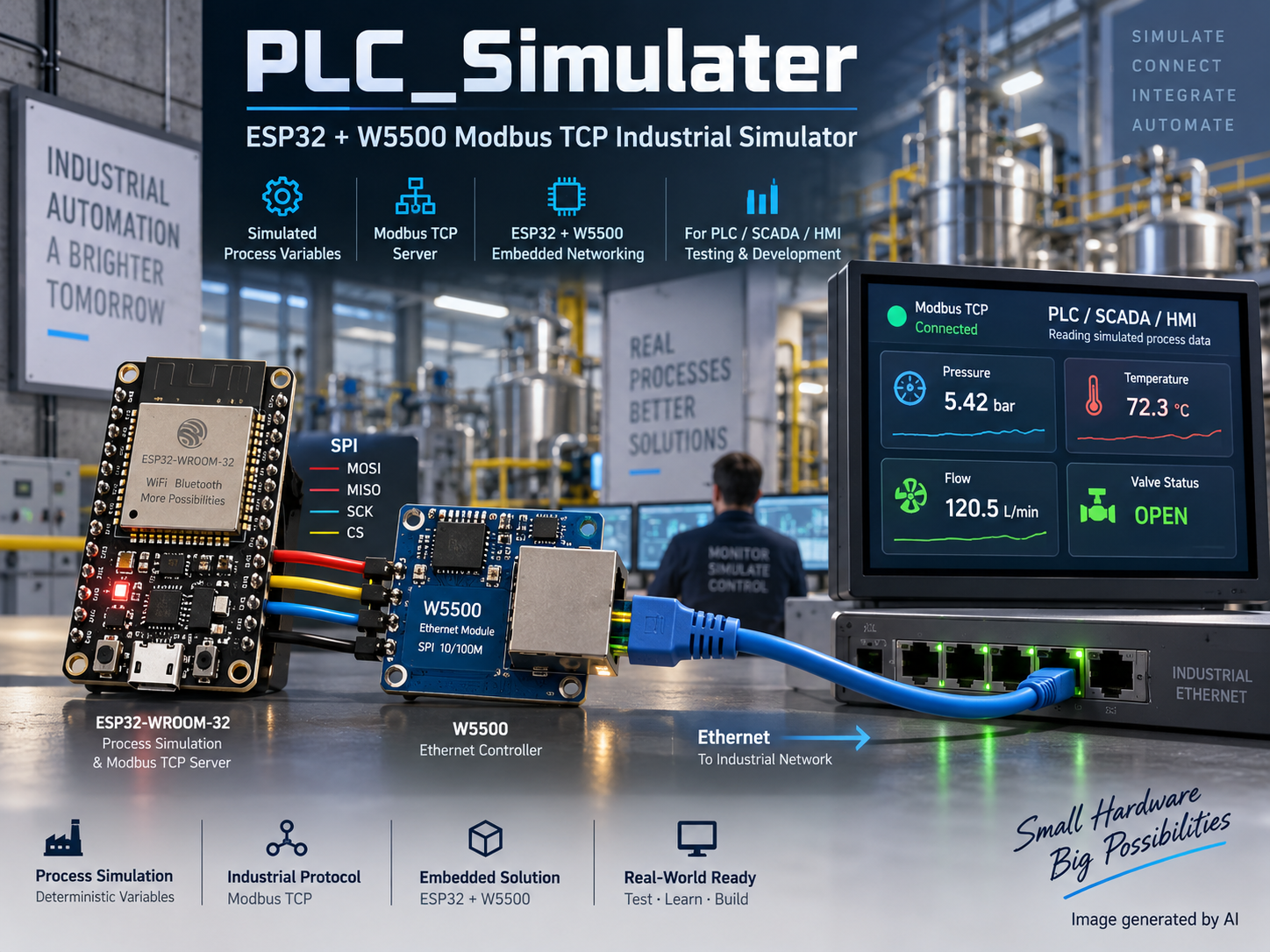
IndustrialSimulator는 ESP32-WROOM32에 WIZnet W5500 이더넷 컨트롤러를 붙인 ESP-IDF 펌웨어 프로젝트다. 산업 공정 변수를 결정적으로 생성해 Modbus TCP 서버로 노출하며, 하나의 데모 애플리케이션이 아니라 재사용 가능한 ESP-IDF 컴포넌트 묶음으로 구성돼 있다. 목적은 좁고 분명하다. SCADA 화면, HMI 패널, 히스토리안, PLC를 상대하는 테스트 스크립트에게 실제 설비 없이도 공정처럼 반응하는 고정된 이더넷 종단을 제공하는 것이다.
이때 값은 자유롭게 흔들리는 난수가 아니라 램프, 삼각파, 지연(lag) 형태의 변화, 경계가 있는 드리프트, 시드가 고정된 노이즈로 만들어진다. 그래서 같은 프로파일을 두 번 돌리면 같은 곡선이 나온다. 이 결정성이 이 보드를 단순 데모가 아니라 테스트 픽스처로 만든다. 공개된 트리는 기본 네트워크 신원을 IP 192.168.0.50, 게이트웨이 192.168.0.1, 서브넷 255.255.255.0, Modbus TCP 포트 502로 고정해 두었기 때문에, 클라이언트를 한 번 겨눠 두면 재플래시 이후에도 그대로 쓸 수 있다.
저장소는 Luciferthedevil666/PLC_Simulater이고 기본 브랜치는 main, 최근 푸시는 2026-07-18로 기록돼 있다. 저자 스스로 완성도에 대해 솔직하다. Notes 절은 컴포넌트화된 펌웨어 기반과 Modbus·공정 코어는 동작하지만, W5500 소켓 버퍼 동작과 장시간 성능 측정은 실제 보드에서의 하드웨어 검증이 아직 필요하다고 적고 있다. 이 글은 공개된 소스가 말하는 사실만 옮기고, 저자가 미검증이라고 표시한 부분은 그대로 미검증으로 표시한다.
하드웨어·소프트웨어 구성
부품 목록은 일부러 짧다. ESP32-WROOM32 모듈이 애플리케이션 프로세서를 맡고, W5500 이더넷 컨트롤러가 SPI 버스에 붙어 유선 네트워크를 담당하며, USB UART가 로깅과 플래싱을 나르고, 5 V USB가 전원을 공급한다. 디스플레이도, 확장 보드도, 아날로그 프런트엔드도 없다. 이 설계에서 모든 공정 값은 측정되는 것이 아니라 계산되기 때문이다.
네트워크 신원은 구조적으로 고정이다. 기본값은 IP 주소 192.168.0.50, 게이트웨이 192.168.0.1, 서브넷 마스크 255.255.255.0, Modbus TCP 포트 502다. README는 NVS 설정을 읽어 들인 뒤 시작 시점에 이더넷 신원을 강제로 static으로 고정한다고 명시하고, 그 이유도 함께 적는다. 예전에 저장된 설정이 시뮬레이터를 다른 서브넷으로 되돌려 보내는 일을 막기 위해서다. 보드 한 대를 여러 사람이 공유하고 재플래시하며 망을 옮겨 다니는 실험대에서, 이 한 줄의 규칙이 "시뮬레이터는 .50에 있다"와 오후 내내 ARP를 훑는 상황을 가른다.
핀 배치는 드라이버마다 흩어지지 않고 components/bsp/src/industrial_bsp.c 한 곳에 모여 있다.
W5500 CS    GPIO5     SPI MISO   GPIO19
W5500 RST   GPIO4     SPI MOSI   GPIO23
W5500 INT   GPIO34    SPI SCLK   GPIO18
Status LED  GPIO2
헤더 components/bsp/include/industrial_bsp.h는 스스로를 ESP32-WROOM32와 W5500 배선을 위한 보드 서포트 패키지라고 설명하며, 핀 열거형은 INDUSTRIAL_BSP_PIN_W5500_CS로 시작해 INDUSTRIAL_BSP_PIN_W5500_RST로 이어진다. 사용하는 쪽은 숫자를 박아 넣는 대신 이 열거형을 통해 핀을 조회한다. components/spi/src/industrial_spi.c는 .spics_io_num 값을 industrial_bsp_get_gpio(INDUSTRIAL_BSP_PIN_W5500_CS)에서 받아 온다. 덕분에 칩 실렉트를 다른 GPIO로 옮기는 일은 트리 전체를 뒤지는 작업이 아니라 보드 계층의 한 줄 수정이 된다.
소프트웨어 쪽은 별도 빌드 시스템 없는 표준 ESP-IDF 빌드다. ESP-IDF를 설치하고 타깃을 지정한 뒤 빌드한다.
idf.py set-target esp32
idf.py build
이어서 플래시하고 USB UART로 로그를 본다.
idf.py flash monitor
추가 사진은 원본 저장소에서 볼 수 있다: https://github.com/Luciferthedevil666/PLC_Simulater
시스템 구조
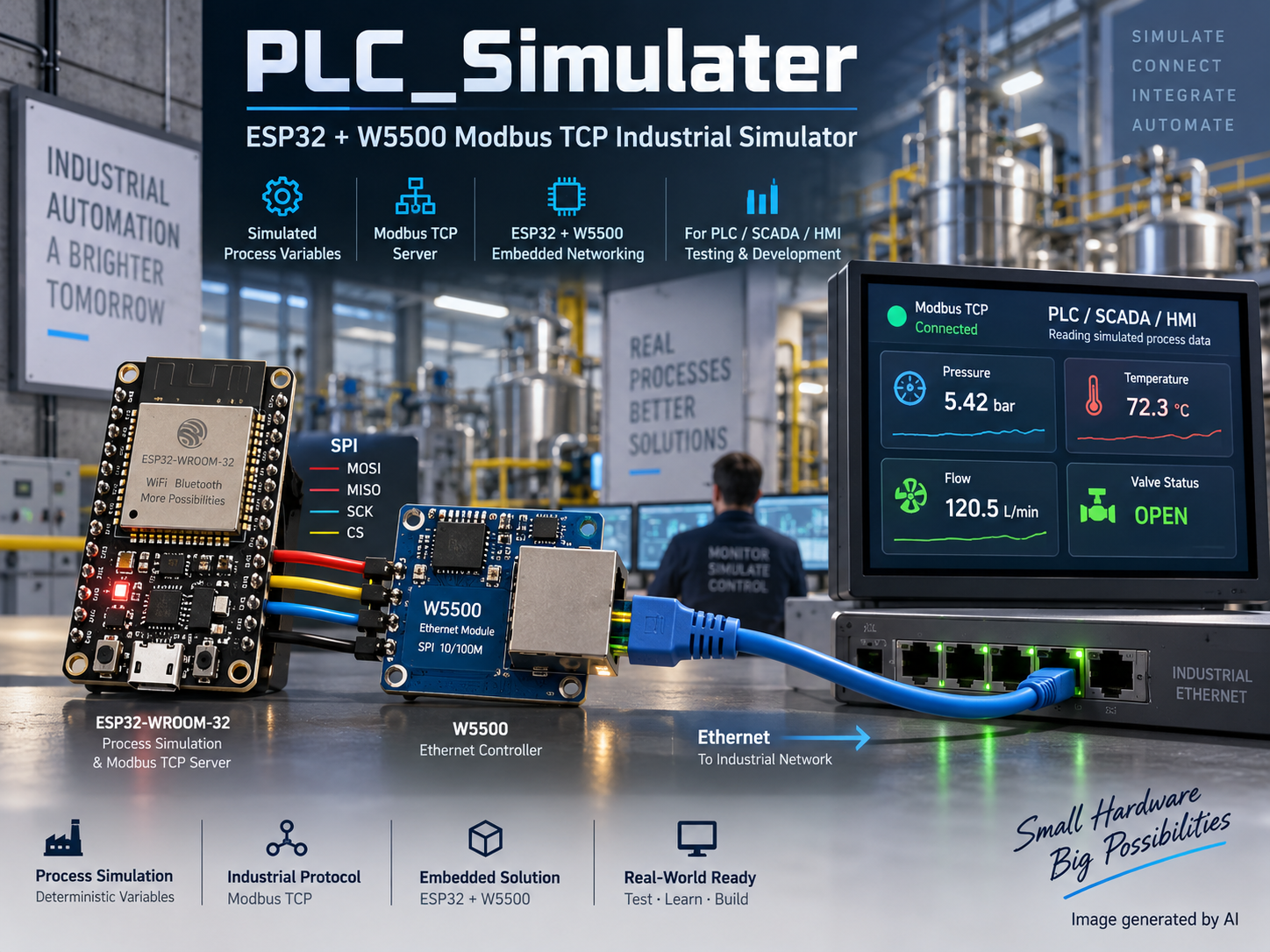
시작 순서가 곧 구조다. main/app_main.c는 모듈을 의존 순서대로 올린다. (1) 로거, (2) NVS 저장소와 설정, (3) BSP, (4) SPI, (5) 레지스터 데이터베이스, (6) 공정 시뮬레이터, (7) W5500 이더넷 매니저, (8) Modbus TCP 서버, (9) 진단, (10) 워치독, (11) FreeRTOS 런타임 태스크 순이다. 핀 맵과 SPI 버스가 존재하기 전에는 선에 닿는 어떤 것도 시작하지 않고, 레지스터 데이터베이스는 그 값을 읽어 주는 서버보다 먼저 존재한다.
같은 형태가 트리 안에서 두 번 더 반복된다. docs/ARCHITECTURE.md는 계층을 bsp -> spi -> w5500 -> ethernet -> network 사슬로 그리고, W5500이 이더넷 컨트롤러 레지스터와 소켓 명령을 소유한다고 분명히 적는다. CMake 파일은 그 규칙을 강제한다. components/w5500은 REQUIRES common bsp spi로, components/ethernet은 REQUIRES common w5500으로, components/tcp는 REQUIRES common w5500 modbus로 등록된다. 문서에만 있는 계층 규칙은 시간이 지나면 썩지만, idf_component_register에도 적힌 계층 규칙은 누군가 층을 건너뛰는 순간 빌드가 깨진다.
Modbus 컴포넌트는 MBAP 파싱과 응답 생성을 처음부터 직접 구현했고, 기능 코드 03(홀딩 레지스터 읽기), 04(입력 레지스터 읽기), 06(단일 홀딩 레지스터 쓰기), 16(다중 홀딩 레지스터 쓰기)을 지원한다. 레지스터 데이터베이스는 홀딩 1000개와 입력 500개를 제공하는데, 이는 데모용 태그 몇 개가 아니라 그럴듯한 설비 주소 맵을 펼쳐 볼 수 있는 크기다.
그 레지스터를 읽을 가치가 있게 만드는 것은 공정 시뮬레이터다. 램프, 삼각파, 지연 형태의 변화, 경계가 있는 드리프트, 시드 고정 노이즈로 결정적 값을 만들고, 정상 운전, 기동, 정지, 비상 정지, 센서 고장, 고온, 저압, 펌프 고장, 밸브 고장, 정전, 유지보수 모드 프로파일을 갖추고 있다. 특히 고장 프로파일이 가져다 쓸 만한 부분이다. 비상 정지나 고착된 밸브, 죽은 센서는 실제 설비로는 재현하기 가장 어려운 상태인데, 여기서는 프로파일 선택 하나로 끝난다.
WIZnet W5500의 역할
이 설계에서 W5500은 마지막에 덧붙인 주변장치가 아니라, 그 위의 모든 코드가 기대어 작성된 계층이다. components/w5500/include/industrial_w5500.h는 스스로를 저수준 W5500 레지스터·소켓 드라이버라고 밝히고, 구현부인 components/w5500/src/industrial_w5500.c는 레지스터 단위로 동작한다. W5500_COMMON_BLOCK을 0x00으로, W5500_VERSIONR을 0x0039로 정의하는데, 각각 공통 레지스터 블록 선택과 칩 버전 레지스터다. 드라이버가 SPI 링크가 실제로 살아 있는지 확인할 때 가장 먼저 읽는 값이다. tests/README.md도 점검 항목에 W5500 버전 검출을 올려 두었다. 같은 생각을 주석이 아니라 테스트로 적어 둔 셈이다.
보드 제어는 프로토콜 로직과 분리돼 있다. components/bsp/src/industrial_bsp.c가 industrial_bsp_reset_w5500()을 노출하므로, GPIO4의 하드웨어 리셋 펄스는 보드 계층의 일이 되고 드라이버는 레지스터에만 집중한다. 드라이버 위에서 components/ethernet/src/industrial_ethernet.c는 industrial_w5500.h를 포함한 뒤 industrial_w5500_init(&s_eth.mac, &s_eth.ip, &s_eth.gateway, &s_eth.subnet)으로 신원을 프로그래밍하고, industrial_w5500_is_link_up(&s_eth.link_up)으로 링크 상태를 위층에 알린다.
가장 결정적인 호출은 TCP 계층에 있다. components/tcp/src/industrial_tcp_server.c는 소켓 범위를 순회하면서 industrial_w5500_socket_open_tcp((uint8_t)(TCP_SOCKET_BASE + i), s_config.listen_port)로 각 소켓을 TCP 모드의 리슨 포트에 올리고, industrial_w5500_socket_close((uint8_t)(TCP_SOCKET_BASE + i))로 정리한다. 여기서 다루는 것은 호스트 스택이 나눠 주는 디스크립터가 아니라 W5500 자신의 번호 붙은 하드웨어 소켓이다. 연결 상태와 버퍼링, 핸드셰이크가 컨트롤러 안에 있으므로 ESP32는 공정 모델과 Modbus 프레이밍에 시간을 쓴다. 헤더 components/tcp/include/industrial_tcp_server.h는 그 의도를 그대로 적어 두었다. 애플리케이션 프로토콜을 W5500으로부터 격리하는 TCP 서버 추상화라는 것이다. 그래서 그 위의 Modbus 코드는 레지스터 쓰기를 한 번도 보지 않는다.
주의할 점 하나는 각주가 아니라 이 자리에 적는 편이 맞다. README는 W5500 소켓 버퍼 동작과 장시간 성능 측정에 대해 실제 보드에서의 하드웨어 검증이 아직 필요하다고 밝힌다. 소켓 배선 코드는 이미 작성돼 있고 소스로 검토할 수 있지만, 여러 클라이언트가 지속적으로 폴링할 때 다중 소켓 버퍼가 어떻게 버티는지는 아직 확인되지 않았다. 그리고 그 부하야말로 팀이 도구를 이 시뮬레이터에 겨누는 순간 곧바로 걸리는 부하다.
자주 묻는 질문
실제 공정 장비가 있어야 쓸 수 있나? 아니다. Modbus로 나가는 모든 값은 펌웨어 안의 공정 시뮬레이터가 만든다. 필요한 하드웨어는 ESP32-WROOM32, SPI에 붙는 W5500 모듈, 전원과 로깅용 USB 케이블, 그리고 클라이언트로 이어지는 이더넷 링크가 전부다.
어떤 Modbus 기능을 지원하나? 기능 코드 03(홀딩 레지스터 읽기), 04(입력 레지스터 읽기), 06(단일 홀딩 레지스터 쓰기), 16(다중 홀딩 레지스터 쓰기)이다. MBAP 파싱과 응답 생성은 Modbus 컴포넌트에서 직접 구현했고, 레지스터 데이터베이스는 기본 포트 502에서 홀딩 1000개와 입력 500개를 제공한다.
IP 주소를 바꿀 수 있나? 기본값은 192.168.0.50에 게이트웨이 192.168.0.1, 서브넷 255.255.255.0이며, NVS 설정을 읽은 뒤 시작 시점에 이더넷 신원을 강제로 static으로 고정한다. 오래된 저장 설정이 보드를 다른 서브넷으로 옮겨 놓지 못하게 하려는 조치다. README는 기본값과 이 시작 규칙은 문서화했지만 별도의 프로비저닝 인터페이스는 설명하지 않는다. 따라서 주소는 클라이언트가 통신 중에 협상할 수 있는 값이 아니라 빌드와 NVS 설정 값으로 다루는 편이 맞다.
W5500은 어떤 핀을 쓰나? 칩 실렉트는 GPIO5, 리셋은 GPIO4, 인터럽트는 GPIO34이며, SPI 버스는 SCLK GPIO18, MOSI GPIO23, MISO GPIO19를 쓰고 상태 LED는 GPIO2다. 모두 보드 서포트 패키지에 한 번만 정의되고 industrial_bsp_get_gpio()로 조회된다.
완성도는 어느 정도인가? 저자의 Notes는 이 저장소를 컴포넌트화된 펌웨어 기반과 동작하는 Modbus·공정 코어라고 부르며, W5500 소켓 버퍼 동작과 장시간 성능 측정은 실제 보드 검증이 아직 필요하다고 적는다. Modbus와 시뮬레이션 계층은 쓸 수 있는 상태로, 지속 부하 특성은 아직 측정되지 않은 값으로 보면 된다.
재사용 조건은 어떻게 되나? 이 글을 쓰는 데 사용한 저장소 기록에는 라이선스 정보가 없다. 코드를 읽는 수준을 넘어 재사용할 계획이라면 저자에게 먼저 확인하는 편이 안전하다.
저자 소개
이 프로젝트는 GitHub 사용자 Luciferthedevil666이 공개했고, 기본 브랜치는 main, 가장 최근 푸시는 2026-07-18로 기록돼 있다. 이 글을 위해 수집한 프로필 메타데이터에는 표시 이름, 공개 이메일, 블로그, 소셜 계정이 모두 비어 있고 저장소 설명 필드도 없다. 결국 코드와 그에 딸린 문서가 저자가 공개적으로 남긴 진술의 전부다.
-
GitHub Repository
Original project repository
