
How Does AutoAimCombatBot Combine Mecanum Drive, Vision Tracking, and W5500 Web Status?
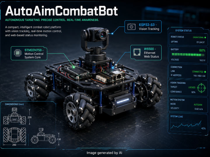
A dual-chip STM32H750 and ESP32-S3 combat robot platform that combines mecanum drive, visual auto-aim gimbal control, and W5500-based web status monitoring.
📌 Overview
AutoAimCombatBot is a dual-chip mecanum wheel combat robot platform based on STM32H750XBH6 and ESP32-S3. The STM32H750 side handles real-time chassis control, encoder feedback, PS2 gamepad input, servo gimbal control, LCD display, and W5500-based web status monitoring. The ESP32-S3 side handles camera-based visual tracking and sends PAN/TILT angle commands to the STM32 through I2C.
The project is modeled around a RoboMaster-style small combat robot concept, but its technical value is broader than the theme. It shows how a real-time MCU, a vision processor, and an Ethernet controller can be divided into clear roles: STM32H750 for control, ESP32-S3 for vision tracking, and W5500 for wired web status viewing.
System Configuration
The repository is organized into two main firmware areas.
H7-CombatBot/ contains the STM32H750 main control firmware. It is built with Keil MDK V5.27 and STM32CubeMX, and it uses FreeRTOS v10.3.1 with heap_4. The build entry is H7-CombatBot/MDK-ARM/Project.uvprojx. The README reports a firmware size of about Code 49KB and ZI 223KB.
R5-tracker/ contains the ESP32-S3 visual tracking firmware. It is built with ESP-IDF and ESP-DL. The vision side uses an OV3660 camera with RGB565 image capture, HSV color recognition, blob scanning, and incremental PD tracking.
The main controller is STM32H750XBH6, a Cortex-M7 MCU running at 400MHz. It manages the mecanum chassis, motor drivers, encoder feedback, PS2 gamepad control, servo gimbal, LCD display, and Ethernet status server.
The chassis uses an O-layout mecanum wheel structure. Four incremental encoders are connected to TIM2 through TIM5 in quadrature mode. Two TB6612 motor drivers are controlled by TIM1 CH1 to CH4 PWM. The README describes the drive control as independent four-wheel closed-loop speed control using incremental PD control.
Manual operation is handled by a PS2 wireless gamepad over SPI2. The left joystick controls forward, backward, and lateral movement. The right joystick controls rotation. DPAD provides full-range movement in four directions. L2 and R2 control PAN movement, L1 and R1 control TILT movement, and SELECT switches between manual mode and automatic visual tracking mode.
The gimbal uses two DS3218 servos for PAN and TILT. They are driven by TIM15 CH1 and TIM15 CH2 using 50Hz PWM. TIM7 is used for trajectory step smoothing, allowing the gimbal to move gradually rather than jumping directly to a new angle.
The display uses an ST7789 240 x 320 RGB565 LCD over SPI5. It shows driving mode and battery level. Ethernet is handled by W5500 over SPI4. The README maps the W5500 path to http_server.c, which provides web-based status viewing.
System Architecture & Data Flow
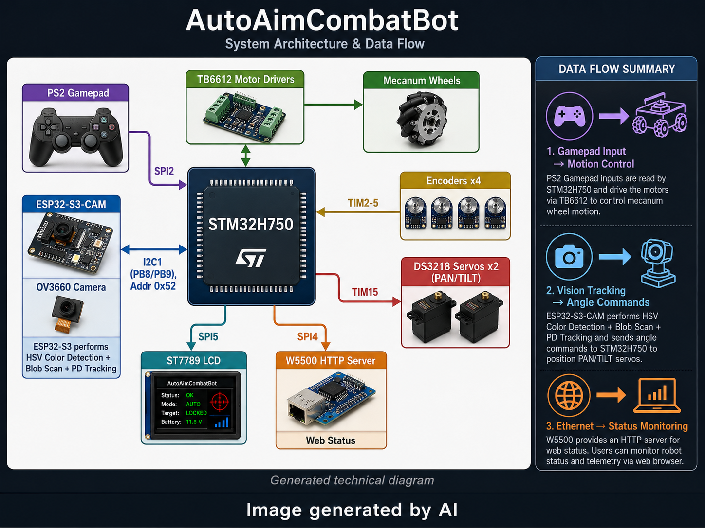
The main design idea is workload separation. STM32H750 handles deterministic real-time control, while ESP32-S3 handles image capture and visual target tracking. Instead of sending camera frames to the STM32, the ESP32-S3 sends compact PAN/TILT angle data through I2C.
The PS2 gamepad path starts from SPI2 and enters ps2_control.c. Movement commands are passed to robot.c, where mecanum kinematics and PID or PD control are handled. Motor output is sent through tb6612.c to the TB6612 drivers. Encoder feedback from TIM2 through TIM5 is processed by encoder.c and returned to robot.c for closed-loop speed control.
The visual tracking path starts from the ESP32-S3-CAM. The OV3660 camera captures RGB565 frames. ESP-DL HSV color detection identifies the target color, with the README describing green as the default tracked object. Blob scanning finds the largest connected area, and an incremental PD controller calculates the PAN/TILT target angle.
The ESP32-S3 works as an I2C slave at address 0x52. The STM32 sends a 1-byte command and reads a 4-byte response, with a 20ms timeout. For command 0x10, the ESP32-S3 returns pan_hi, pan_lo, tilt_hi, and tilt_lo. These values are signed 16-bit servo angles in 0.01 degree units, with a range of ±6000.
The system data flow can be summarized as follows.
PS2 gamepad --SPI2--> ps2_control.c --> robot.c (kinematics + PID) --> tb6612.c --> motors
                        |                 ^
                        +--> servo.c      |
ESP32-S3 --I2C1--> tracking.c --> servo.c |
encoders --TIM2-5--> encoder.c --> robot.c
LCD --SPI5--> ui.c
W5500 --SPI4--> http_server.c
This flow shows the interface map clearly. SPI2 is used for the PS2 gamepad, SPI4 for W5500 Ethernet, SPI5 for the ST7789 LCD, I2C1 for communication between STM32 and ESP32-S3, TIM1 for motor PWM, TIM2 to TIM5 for encoder feedback, TIM15 for servo PWM, and TIM7 for smooth gimbal movement.
⚙️ Role of the WIZnet Chip
The WIZnet chip used in this project is W5500. The README explicitly lists W5500 as the Ethernet module, connected through SPI4. The system flow also maps W5500 --SPI4--> http_server.c, and the feature list describes an Ethernet Web function using a W5500 HTTP Server for web-based status viewing.
TOE is classified as Yes. W5500 is a hardware TCP/IP Ethernet controller. In a typical W5500-based HTTP server design, the chip handles TCP/IP socket processing through hardware offload instead of requiring the host MCU to run a full software TCP/IP stack. In this project, the W5500 path is used for web status monitoring rather than motor control or visual tracking.
This role is useful because the STM32H750 already handles multiple timing-sensitive tasks: mecanum drive control, encoder feedback, servo PWM, PS2 input processing, I2C tracking input, LCD output, and FreeRTOS scheduling. Using W5500 for Ethernet status viewing gives the system a dedicated wired monitoring path without forcing the ESP32-S3 vision module to also handle networking.
Hybrid Network is classified as No. Although the system includes both ESP32-S3 and W5500, the README describes ESP32-S3 as a visual tracking module, not as an active Wi-Fi network interface. A dual-chip architecture is not the same as a hybrid network. Hybrid Network would require confirmed simultaneous wired and wireless network operation.
Where It Fits - Value & Limits
AutoAimCombatBot is valuable as an embedded robotics integration example. It combines mecanum wheel motion, encoder feedback, PS2 gamepad control, servo gimbal control, camera-based visual tracking, LCD display, and W5500 Ethernet monitoring in one system.
Its strongest design point is role separation. STM32H750 focuses on real-time control. ESP32-S3 focuses on visual tracking. W5500 focuses on web status viewing. This is easier to reason about than forcing motor loops, camera processing, UI, and networking into a single overloaded controller.
The interface design also has strong learning value. The project uses SPI2 for the PS2 gamepad, SPI4 for W5500 Ethernet, SPI5 for ST7789 LCD, I2C1 for STM32 to ESP32-S3 communication, TIM1 for motor PWM, TIM2 through TIM5 for encoder feedback, TIM15 for servo PWM, and TIM7 for gimbal trajectory smoothing.
The vision tracking structure is lightweight and practical. Instead of relying on a heavy object detection model, the ESP32-S3 side uses OV3660 RGB565 capture, ESP-DL HSV color detection, blob scanning, and incremental PD tracking. This is suitable for controlled color-target tracking, where fast response and simple tuning matter more than general object recognition.
The limitations are also clear. Color-based tracking can be affected by lighting, background color, target size, camera exposure, and motion blur. The README confirms the architecture and interface map, but deeper implementation claims require source-level review, especially inside http_server.c, tracking.c, servo.c, robot.c, and the FreeRTOS task structure.
Related WIZnet Maker Projects
This project is related because it uses W5500 to add Ethernet capability to an ESP32-based environment. AutoAimCombatBot differs because ESP32-S3 is used for visual tracking, while W5500 is connected to the STM32 side for HTTP status viewing.
This project is related because it combines FreeRTOS and W5500 in an embedded networking context. AutoAimCombatBot uses FreeRTOS on STM32H750 and connects W5500 to an HTTP status server, while the referenced project focuses on LwIP and MACRAW integration.
This project is related because it uses W5500 for embedded network communication. AutoAimCombatBot uses W5500 for HTTP status viewing, while the referenced project focuses on MQTT messaging.
❓ FAQ
Q. What kind of project is AutoAimCombatBot? It is a dual-chip mecanum wheel robot platform that combines STM32H750 real-time control, ESP32-S3 visual tracking, and W5500 Ethernet web status monitoring.
Q. Does it use WIZnet hardware? Yes. The README lists W5500 as the Ethernet module and maps it through SPI4 to http_server.c.
Q. Is TOE used in this project? Yes. W5500 is a hardware TCP/IP Ethernet controller, and the project uses it for a W5500 HTTP Server status viewing path.
Q. Is it a Hybrid Network project? No. ESP32-S3 is used as a visual tracking module, while W5500 provides wired Ethernet status viewing. The README does not describe simultaneous wired and wireless network operation.
Q. What is the main technical value? The value is the clean split between real-time motion control, visual tracking, and Ethernet monitoring, with concrete interfaces such as SPI2, SPI4, SPI5, I2C1, TIM1, TIM2 to TIM5, TIM15, and TIM7.
한국어 (Korean)
개요
AutoAimCombatBot은 STM32H750XBH6와 ESP32-S3를 함께 사용하는 듀얼 칩 기반 메카넘 휠 전투 로봇 플랫폼입니다. STM32H750은 실시간 섀시 제어, 엔코더 피드백, PS2 게임패드 입력, 서보 짐벌 제어, LCD 표시, W5500 기반 웹 상태 모니터링을 담당합니다. ESP32-S3는 카메라 기반 시각 추적을 수행하고, 계산된 PAN/TILT 각도 명령을 I2C로 STM32에 전달합니다.
이 프로젝트는 RoboMaster 스타일의 소형 전투 로봇 콘셉트를 기반으로 하지만, 기술적 가치는 콘셉트보다 구조에 있습니다. 실시간 MCU, 비전 처리 모듈, Ethernet 컨트롤러를 각각 분리해 배치한 사례입니다. STM32H750은 제어, ESP32-S3는 비전 추적, W5500은 유선 웹 상태 확인을 담당합니다.
시스템 구성
저장소는 두 개의 주요 펌웨어 영역으로 구성됩니다.
H7-CombatBot/에는 STM32H750 메인 제어 펌웨어가 들어 있습니다. 개발 환경은 Keil MDK V5.27과 STM32CubeMX이며, FreeRTOS v10.3.1과 heap_4를 사용합니다. 빌드 진입점은 H7-CombatBot/MDK-ARM/Project.uvprojx입니다. README에는 펌웨어 크기가 약 Code 49KB, ZI 223KB로 표시되어 있습니다.
R5-tracker/에는 ESP32-S3 시각 추적 펌웨어가 들어 있습니다. 개발 환경은 ESP-IDF와 ESP-DL입니다. 비전 쪽은 OV3660 카메라의 RGB565 이미지 캡처, HSV 색상 인식, Blob 탐색, 증분형 PD 추적을 사용합니다.
메인 컨트롤러는 STM32H750XBH6입니다. Cortex-M7 기반 400MHz MCU이며, 메카넘 섀시, 모터 드라이버, 엔코더 피드백, PS2 게임패드 제어, 서보 짐벌, LCD 표시, Ethernet 상태 서버를 관리합니다.
섀시는 O형 메카넘 휠 구조입니다. 4개의 증분형 엔코더는 TIM2부터 TIM5까지 직교 엔코더 모드로 연결됩니다. TB6612 모터 드라이버 2개는 TIM1 CH1부터 CH4까지의 PWM으로 제어됩니다. README는 주행 제어를 증분형 PD 기반 4륜 독립 속도 폐루프 제어로 설명합니다.
수동 조작은 SPI2에 연결된 PS2 무선 게임패드가 담당합니다. 왼쪽 조이스틱은 전진, 후진, 좌우 평행 이동을 제어합니다. 오른쪽 조이스틱은 회전을 제어합니다. DPAD는 네 방향 최대 속도 이동을 담당합니다. L2와 R2는 PAN 움직임, L1과 R1은 TILT 움직임을 제어합니다. SELECT 버튼은 수동 모드와 자동 시각 추적 모드를 전환합니다.
짐벌은 DS3218 서보 2개로 PAN과 TILT를 구성합니다. TIM15 CH1과 TIM15 CH2에서 50Hz PWM으로 구동합니다. TIM7은 궤적 스텝 기반의 부드러운 이동에 사용됩니다. 그래서 짐벌이 목표 각도로 갑자기 튀지 않고 단계적으로 이동할 수 있습니다.
디스플레이는 SPI5에 연결된 ST7789 240 x 320 RGB565 LCD입니다. 주행 모드와 배터리 잔량을 표시합니다. Ethernet은 SPI4에 연결된 W5500이 담당합니다. README는 W5500 경로를 http_server.c로 연결해 웹 기반 상태 확인 기능을 제공한다고 설명합니다.
시스템 아키텍처 및 데이터 흐름
핵심 설계 아이디어는 작업 분리입니다. STM32H750은 결정성이 중요한 실시간 제어를 담당하고, ESP32-S3는 이미지 캡처와 시각 목표 추적을 담당합니다. ESP32-S3는 카메라 프레임 전체를 STM32로 보내지 않고, 계산된 PAN/TILT 각도 데이터만 I2C로 보냅니다.
PS2 게임패드 입력 경로는 SPI2에서 시작해 ps2_control.c로 들어갑니다. 이동 명령은 robot.c로 전달되고, 이곳에서 메카넘 운동학과 PID 또는 PD 제어가 처리됩니다. 모터 출력은 tb6612.c를 통해 TB6612 드라이버로 전달됩니다. TIM2부터 TIM5까지 들어오는 엔코더 피드백은 encoder.c에서 처리되어 robot.c로 돌아가 폐루프 속도 제어에 사용됩니다.
시각 추적 경로는 ESP32-S3-CAM에서 시작됩니다. OV3660 카메라는 RGB565 프레임을 캡처합니다. ESP-DL HSV 색상 검출은 목표 색상을 식별하며, README에서는 기본 추적 대상이 녹색 물체라고 설명합니다. Blob 탐색은 가장 큰 연결 영역을 찾고, 증분형 PD 제어기는 PAN/TILT 목표 각도를 계산합니다.
ESP32-S3는 I2C Slave 주소 0x52로 동작합니다. STM32는 1바이트 명령을 보내고, 20ms 타임아웃 안에 4바이트 응답을 읽습니다. 명령 0x10에 대해 ESP32-S3는 pan_hi, pan_lo, tilt_hi, tilt_lo를 반환합니다. 이 값은 0.01도 단위의 signed 16-bit 서보 각도이며, 범위는 ±6000입니다.
시스템 데이터 흐름은 다음과 같이 요약할 수 있습니다.
PS2 게임패드 --SPI2--> ps2_control.c --> robot.c (운동학 + PID) --> tb6612.c --> 모터
                          |                 ^
                          +--> servo.c      |
ESP32-S3 --I2C1--> tracking.c --> servo.c   |
엔코더 --TIM2-5--> encoder.c --> robot.c
LCD --SPI5--> ui.c
W5500 --SPI4--> http_server.c
이 흐름은 인터페이스 구성을 명확히 보여줍니다. SPI2는 PS2 게임패드, SPI4는 W5500 Ethernet, SPI5는 ST7789 LCD, I2C1은 STM32와 ESP32-S3 통신, TIM1은 모터 PWM, TIM2부터 TIM5는 엔코더 피드백, TIM15는 서보 PWM, TIM7은 부드러운 짐벌 이동에 사용됩니다.
WIZnet 칩의 역할
이 프로젝트에서 사용된 WIZnet 칩은 W5500입니다. README에는 W5500이 Ethernet 모듈로 명시되어 있고, SPI4로 연결된다고 되어 있습니다. 시스템 흐름에서도 W5500 --SPI4--> http_server.c로 표시되어 있으며, 기능 설명에는 W5500 HTTP Server를 통한 웹 기반 상태 확인이 포함되어 있습니다.
TOE는 Yes로 분류합니다. W5500은 하드웨어 TCP/IP Ethernet 컨트롤러입니다. 일반적인 W5500 기반 HTTP Server 설계에서는 호스트 MCU가 전체 TCP/IP 스택을 소프트웨어로 처리하는 대신, 칩 내부의 하드웨어 TCP/IP socket 기능을 사용합니다. 이 프로젝트에서 W5500 경로는 모터 제어나 시각 추적이 아니라 웹 상태 모니터링에 사용됩니다.
이 역할은 유용합니다. STM32H750은 이미 메카넘 구동 제어, 엔코더 피드백, 서보 PWM, PS2 입력 처리, I2C 추적 입력, LCD 출력, FreeRTOS 스케줄링을 맡고 있습니다. 여기에 W5500을 Ethernet 상태 확인 경로로 사용하면, ESP32-S3 비전 모듈에 네트워크 역할까지 얹지 않아도 됩니다.
Hybrid Network는 No로 분류합니다. 시스템에는 ESP32-S3와 W5500이 함께 등장하지만, README에서 ESP32-S3는 시각 추적 모듈로 설명됩니다. 활성 Wi-Fi 네트워크 인터페이스로 설명되지 않습니다. 듀얼 칩 구조와 하이브리드 네트워크는 다릅니다. Hybrid Network라고 하려면 유선과 무선 네트워크가 동시에 동작한다는 근거가 필요합니다.
활용 분야와 한계
AutoAimCombatBot은 임베디드 로봇 통합 사례로 가치가 있습니다. 메카넘 휠 이동, 엔코더 피드백, PS2 게임패드 조종, 서보 짐벌 제어, 카메라 기반 시각 추적, LCD 표시, W5500 Ethernet 모니터링이 하나의 시스템 안에 결합되어 있습니다.
가장 강한 설계 포인트는 역할 분리입니다. STM32H750은 실시간 제어에 집중합니다. ESP32-S3는 시각 추적에 집중합니다. W5500은 웹 상태 확인에 집중합니다. 모터 루프, 카메라 처리, UI, 네트워크를 하나의 컨트롤러에 몰아넣는 구조보다 이해와 디버깅이 쉽습니다.
인터페이스 설계도 학습 가치가 높습니다. 이 프로젝트는 PS2 게임패드에 SPI2, W5500 Ethernet에 SPI4, ST7789 LCD에 SPI5, STM32와 ESP32-S3 통신에 I2C1, 모터 PWM에 TIM1, 엔코더 피드백에 TIM2부터 TIM5, 서보 PWM에 TIM15, 짐벌 궤적 smoothing에 TIM7을 사용합니다.
시각 추적 구조는 가볍고 현실적입니다. ESP32-S3 쪽은 무거운 객체 검출 모델 대신 OV3660 RGB565 캡처, ESP-DL HSV 색상 검출, Blob 탐색, 증분형 PD 추적을 사용합니다. 이 방식은 범용 객체 인식보다는 통제된 색상 타깃 추적에서 빠른 반응과 쉬운 튜닝에 유리합니다.
한계도 분명합니다. 색상 기반 추적은 조명, 배경 색상, 대상 크기, 카메라 노출, 모션 블러에 영향을 받을 수 있습니다. README는 아키텍처와 인터페이스 구성을 확인해 주지만, 더 깊은 구현 판단에는 소스 코드 확인이 필요합니다. 특히 http_server.c, tracking.c, servo.c, robot.c, FreeRTOS 태스크 구조는 소스 기준으로 추가 검토하면 더 정확합니다.
관련 WIZnet Maker 프로젝트
이 프로젝트는 W5500을 이용해 ESP32 기반 환경에 Ethernet 기능을 추가한다는 점에서 관련이 있습니다. AutoAimCombatBot은 ESP32-S3를 시각 추적에 사용하고, W5500은 STM32 쪽 HTTP 상태 확인 경로에 연결된다는 점이 다릅니다.
이 프로젝트는 FreeRTOS와 W5500을 함께 다루는 임베디드 네트워크 사례라는 점에서 관련이 있습니다. AutoAimCombatBot은 STM32H750에서 FreeRTOS를 사용하고 W5500을 HTTP 상태 서버에 연결하며, 해당 프로젝트는 LwIP와 MACRAW 통합에 초점을 둡니다.
이 프로젝트는 W5500을 임베디드 네트워크 통신에 사용한다는 점에서 관련이 있습니다. AutoAimCombatBot은 W5500을 HTTP 상태 확인에 사용하고, 해당 프로젝트는 MQTT 메시징에 초점을 둡니다.
AutoAimCombatBot은 어떤 프로젝트인가요? STM32H750 실시간 제어, ESP32-S3 시각 추적, W5500 Ethernet 웹 상태 모니터링을 결합한 듀얼 칩 기반 메카넘 휠 로봇 플랫폼입니다.
WIZnet 하드웨어를 사용하나요? 네. README에는 W5500이 Ethernet 모듈로 명시되어 있고, SPI4를 통해 http_server.c로 연결된다고 되어 있습니다.
TOE를 사용하는 프로젝트인가요? 네. W5500은 하드웨어 TCP/IP Ethernet 컨트롤러이며, 이 프로젝트에서는 W5500 HTTP Server 상태 확인 경로에 사용됩니다.
Hybrid Network 프로젝트인가요? 아닙니다. ESP32-S3는 시각 추적 모듈로 사용되고, W5500은 유선 Ethernet 상태 확인을 담당합니다. README에는 유선과 무선 네트워크가 동시에 동작한다는 설명이 없습니다.
가장 중요한 기술적 가치는 무엇인가요? 실시간 모션 제어, 시각 추적, Ethernet 모니터링을 분리한 구조입니다. SPI2, SPI4, SPI5, I2C1, TIM1, TIM2부터 TIM5, TIM15, TIM7 같은 구체 인터페이스가 실제 시스템 안에서 역할별로 배치되어 있습니다.