
Hardware WAN Latency Analyzer with STM32 and WIZnet W5500
A bare-metal STM32 device uses WIZnet W5500 Ethernet and timer-based UDP RTT measurement to visualize WAN latency and jitter.
Overview
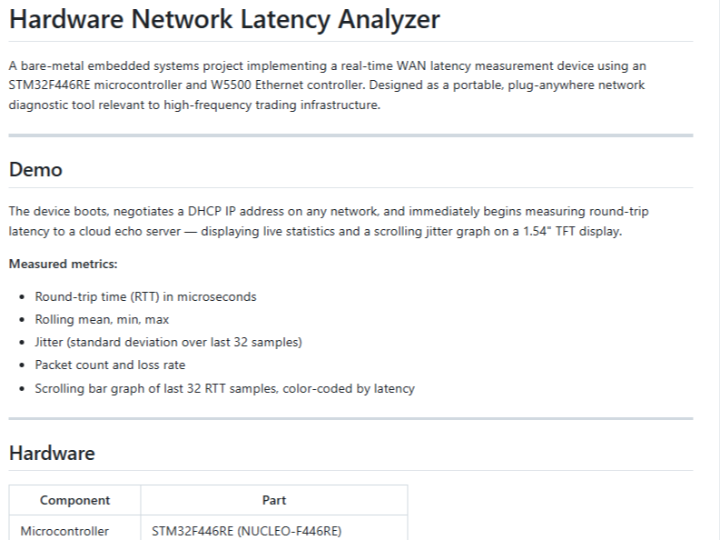
This project is a bare-metal embedded network diagnostic device built around an STM32F446RE microcontroller, a WIZnet W5500 Ethernet controller, and an ST7789 TFT display. It obtains an IP address through DHCP, sends UDP packets to a cloud echo server, measures round-trip time, and displays live latency statistics and a small jitter graph on-device.
Its main value is not that it replaces professional network measurement equipment. Its value is that it makes the latency measurement path explicit: a microcontroller timestamp, a wired Ethernet controller, a UDP echo transaction, an interrupt on packet arrival, and local visualization.
Main Content
The measurement loop is simple and intentionally narrow. The STM32 captures a send-side timestamp using TIM2, sends a short UDP packet through the W5500, waits for the echo response, captures the receive-side timestamp when the W5500 interrupt line fires, and converts the timer delta into microseconds. The firmware then updates current RTT, minimum, maximum, rolling mean, jitter estimate, packet count, and loss count.
The design differs from a typical software ping or application-level network monitor because the measurement endpoint is not a general-purpose operating system. There is no Linux scheduler, user-space networking stack, shell command timing, or desktop UI loop in the measurement path. The project uses a bare-metal firmware loop and interrupt-driven receive timestamping, so the design tries to reduce measurement noise caused by software polling and OS scheduling.
The WIZnet W5500 is central to the design because it provides wired Ethernet connectivity through SPI and includes a hardwired TCP/IP stack with integrated 10/100 Ethernet MAC and PHY. In this project, that means the STM32 can interact with the network through the W5500 socket interface rather than implementing the full Ethernet and IP stack in firmware.
System Context
This device is best understood as a portable Ethernet-attached measurement endpoint. It answers a specific operational question: from this physical Ethernet connection, what round-trip behavior is observed when sending UDP packets to a known echo endpoint?
That boundary matters. The system does not measure every layer of a production service path. It does not validate application latency, exchange gateway behavior, server-side business logic, or packet capture timestamps from both ends of a link. It measures a synthetic UDP echo path from the embedded device to a cloud server and back.
The cloud echo server is therefore not a side detail. Without it, the system would no longer measure WAN round-trip behavior. It would become either a local Ethernet bring-up tool, a display demo, or a firmware timing test, depending on what replaced the server path.
Architecture / Design Considerations
The architecture has four practical layers.
First, the STM32F446RE runs the firmware, initializes peripherals, starts TIM2, registers W5500 SPI callbacks, initializes the display, and repeatedly runs the RTT measurement and display update loop.
Second, the WIZnet W5500 handles wired Ethernet access. The README identifies W5500 reset, SPI initialization, DHCP setup, UDP socket management, and receive interrupt handling as part of the network layer.
Third, TIM2 acts as the local timing reference. The README describes TIM2 as a 32-bit free-running timer at 84 MHz, and the firmware converts timer ticks into microseconds by dividing by 84.
Fourth, the ST7789 display turns the device into a standalone instrument rather than a board that requires a serial terminal or attached PC. The firmware renders RTT, average, minimum, maximum, jitter, packet count, loss count, and a scrolling graph.
The highest-cost failure point is the timing boundary. If the interrupt fires late, if the timer configuration is wrong, if packet arrival is confused with packet processing completion, or if the cloud echo server introduces queueing, the displayed RTT can look precise while representing a different timing path than intended. That is the dangerous kind of measurement error: not obvious failure, but confident-looking data with a shifted meaning.
Removing major components changes the nature of the system. Without the W5500, it is no longer a wired Ethernet measurement device. Without the W5500 interrupt path, receive timing becomes more dependent on firmware polling or software delay. Without TIM2, the project loses its local high-resolution timing basis. Without the echo server, it no longer measures WAN round trip behavior.
Possible Implications
The project is useful as an embedded networking reference, a teaching example for interrupt-driven measurement, and a small diagnostic device for comparing network behavior from a physical Ethernet drop. It also demonstrates why measurement architecture matters as much as the numerical result.
For stricter latency analysis, the design would need additional controls: calibration of local processing overhead, clearer separation of send timestamp and actual wire departure, validation of server-side echo behavior, and possibly synchronized clocks or packet capture equipment. The current design is better read as a focused measurement appliance and educational prototype, not as a complete replacement for production-grade latency instrumentation.
Conclusion
This project is a compact example of embedded network measurement built from ordinary development hardware but organized around a serious measurement idea: keep the timing path small, make packet arrival interrupt-driven, and show latency behavior directly at the device. Its strength is architectural clarity. Its limitation is also clear: it observes one synthetic UDP path, so its results should support network diagnosis rather than become the only basis for operational decisions.
전체 개요
이 저장소는 STM32F446RE 보드, WIZnet W5500 이더넷 컨트롤러, ST7789 TFT 디스플레이를 조합해서 WAN 왕복 지연 시간을 측정하는 임베디드 장치 프로젝트입니다. 장치는 DHCP로 IP를 받은 뒤 UDP 패킷을 클라우드 echo server로 보내고, 돌아온 응답을 기준으로 RTT, 평균, 최솟값, 최댓값, jitter, packet loss를 화면에 표시합니다.
핵심은 “네트워크 지연을 PC 소프트웨어가 아니라 MCU 기반의 독립 장치에서 직접 관찰한다”는 점입니다. 정확히 말하면, 이 프로젝트는 전문 계측기라기보다는 유선 이더넷 기반의 임베디드 지연 측정기에 가깝습니다. 숫자를 예쁘게 보여주는 것보다, 측정 경로를 작고 단순하게 만드는 데 설계의 의미가 있습니다. 인간은 늘 숫자를 보면 믿어버리니, 이런 경계 표시는 좀 필요합니다.
문제의식과 기술적 맥락 재구성
일반적인 네트워크 지연 확인은 PC에서 ping을 실행하거나 애플리케이션 로그를 보는 방식으로 끝나는 경우가 많습니다. 그러나 그런 방식은 운영체제 스케줄링, 사용자 공간 지연, 네트워크 스택 처리 지연, UI 또는 로그 기록 지연이 섞일 수 있습니다.
이 프로젝트의 접근은 그 층을 줄이는 쪽입니다. STM32 bare-metal 펌웨어 위에서 TIM2 하드웨어 타이머를 사용하고, W5500의 INT 핀을 EXTI 인터럽트로 받아 수신 시점을 잡는 구조입니다. 공개 README는 이 구조가 polling jitter를 줄이기 위한 설계라고 설명합니다.
추론임: 기존 PC 기반 측정 대비 이 구조의 핵심 차이는 “네트워크 RTT를 OS 위에서 간접 측정하는 것”이 아니라, “MCU와 이더넷 컨트롤러 사이의 비교적 짧은 경로에서 이벤트를 잡으려는 것”입니다. 다만 이 말은 절대적인 정확도 보장을 뜻하지 않습니다. 이 장치의 timestamp는 여전히 W5500 내부 처리, SPI 전송, 펌웨어 처리 순서, echo server 응답 특성의 영향을 받습니다.
기술 흐름 설명
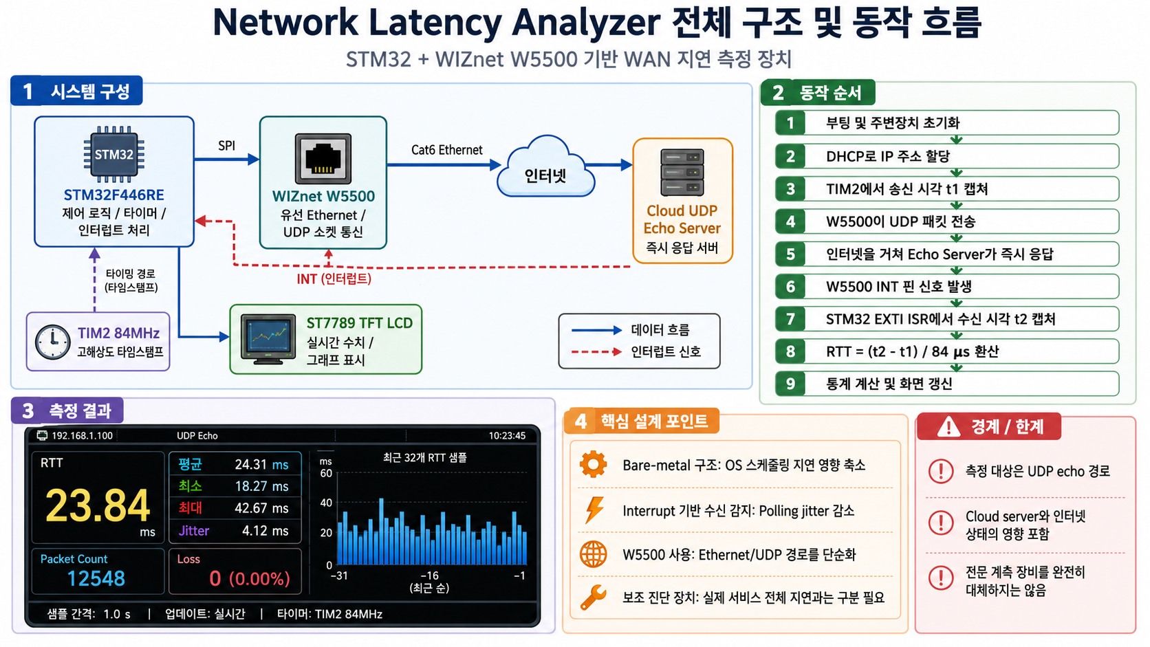
동작 흐름은 다음과 같이 볼 수 있습니다.
- 장치가 부팅됩니다.
- STM32가 GPIO, SPI, TIM2, UART, 디스플레이를 초기화합니다.
- W5500이 초기화되고 DHCP를 통해 IP를 할당받습니다.
- UDP socket이 열립니다.
- STM32가 TIM2 counter 값을 읽어 송신 시각으로 사용합니다.
- 해당 timestamp를 포함한 짧은 UDP packet을 echo server로 보냅니다.
- echo server가 packet을 되돌려보냅니다.
- W5500의 INT 핀이 packet arrival을 알립니다.
- STM32 EXTI ISR에서 TIM2 값을 다시 캡처합니다.
- 두 timestamp 차이를 84로 나누어 마이크로초 단위 RTT로 환산합니다.
- 현재 RTT, 평균, 최소, 최대, jitter, packet count, loss count를 표시합니다.
여기서 데이터 흐름은 단순합니다. MCU가 packet을 만들고, W5500이 Ethernet으로 내보내고, 인터넷 경로와 cloud echo server를 거쳐 응답이 돌아옵니다. 신호 흐름은 조금 다릅니다. 수신 데이터가 들어오면 W5500의 INT 핀이 내려가고, STM32는 그 edge를 EXTI interrupt로 받아 “응답 도착 시점”을 기록합니다.
왜 이런 구조가 나왔는지에 대한 해설
추론임: 이 구조는 “정밀한 네트워크 계측기”를 처음부터 만들기보다는, 제한된 임베디드 보드에서 측정 경로를 최대한 명확히 만들기 위한 선택으로 보입니다. STM32는 범용 MCU이고, W5500은 TCP/IP stack과 Ethernet MAC/PHY를 포함한 컨트롤러이므로, MCU가 복잡한 Ethernet stack을 직접 구현하지 않아도 UDP 통신을 구성할 수 있습니다. WIZnet 공식 설명에서도 W5500은 SPI 기반으로 임베디드 시스템에 인터넷 연결을 제공하고, hardwired TCP/IP stack과 10/100 Ethernet MAC/PHY를 포함한다고 설명합니다.
즉, W5500은 단순한 “랜 포트 부품”이 아닙니다. 이 프로젝트에서는 STM32가 측정 로직과 UI를 담당하고, W5500은 유선 Ethernet 접속과 UDP socket 통신을 담당하는 경계 장치입니다. 이 경계가 있어야 MCU 쪽 코드는 “네트워크 전체 구현”이 아니라 “측정 루프와 표시 로직”에 집중할 수 있습니다.
설계 선택의 배경
이 프로젝트의 설계 선택은 크게 네 가지로 해석할 수 있습니다.
첫째, bare-metal 구조입니다. RTOS나 Linux를 사용하지 않기 때문에 시스템 동작이 단순해집니다. 대신 개발자가 peripheral 초기화, loop timing, interrupt 처리, socket 처리 흐름을 직접 책임져야 합니다.
둘째, WIZnet W5500 사용입니다. W5500이 TCP/IP와 Ethernet 하위 계층을 상당 부분 맡기 때문에 STM32는 SPI와 socket API 중심으로 네트워크 기능을 사용할 수 있습니다. 다만 이 선택은 측정값에 W5500 내부 동작과 SPI 통신 경로가 포함될 수 있다는 의미이기도 합니다.
셋째, TIM2 기반 timestamp입니다. TIM2는 README 기준 84 MHz free-running counter로 설정되어 있고, firmware는 tick 차이를 마이크로초로 환산합니다. 이 선택은 HAL tick 같은 밀리초 단위 시간보다 훨씬 세밀한 측정 기반을 제공합니다.
넷째, cloud echo server 사용입니다. 이 장치는 로컬 링크 테스트가 아니라 WAN 왕복 지연을 보려는 장치입니다. echo server가 없다면 측정 대상은 “인터넷 경로”가 아니라 “로컬 펌웨어와 네트워크 초기화” 수준으로 바뀝니다.
제약 조건과 대안 가능성
이 시스템에서 실패 비용이 가장 큰 구간은 timestamp 경계입니다. packet이 실제 wire에 나간 시점과 firmware가 t1을 찍은 시점이 완전히 같지는 않을 수 있고, 응답 packet이 W5500에 도착한 시점과 EXTI ISR이 실행되는 시점도 완전히 같다고 단정할 수 없습니다. 그럼에도 화면에는 마이크로초 단위 숫자가 나오기 때문에, 사용자가 그 숫자를 절대값으로 오해할 위험이 있습니다.
대안으로는 PC 기반 packet capture, NIC hardware timestamping, PTP 동기화 장비, 양단 timestamp 방식, FPGA 또는 전용 계측 장비가 있습니다. 하지만 그런 대안은 구성 비용과 복잡도가 올라갑니다. 이 프로젝트는 그 대안들과 경쟁하기보다는, 작고 독립적인 장치로 “현재 접속 지점에서 보이는 RTT와 jitter 경향”을 확인하는 보조 수단으로 보는 편이 타당합니다.
추론임: 이 장치가 보조 수단인 이유는 측정 대상이 실제 서비스 transaction이 아니라 synthetic UDP echo path이기 때문입니다. 즉, “이 네트워크가 느린가?”라는 초기 진단에는 도움이 되지만, “실제 거래 시스템, API 서버, DB, gateway 전체 지연이 어디서 발생하는가?”까지 답하지는 못합니다.
생소한 개념에 대한 풀어쓴 설명
RTT는 packet이 목적지까지 갔다가 다시 돌아오는 데 걸린 왕복 시간입니다. 이 프로젝트에서는 UDP packet을 echo server로 보내고, 같은 packet이 돌아오는 시간을 기준으로 계산합니다.
Jitter는 지연 시간의 흔들림입니다. 평균 RTT가 낮아도 jitter가 크면 응답 시간이 들쭉날쭉하다는 뜻입니다. README는 최근 32개 sample 기준의 표준편차를 jitter로 표시한다고 설명합니다.
Interrupt-driven timestamping은 계속 polling하면서 “왔나?”를 확인하는 대신, 하드웨어 신호가 들어왔을 때 즉시 ISR에서 시간을 잡는 방식입니다. 이 프로젝트에서는 W5500 INT 핀이 STM32 PA8 EXTI interrupt로 연결됩니다.
Hardwired TCP/IP는 TCP/IP 처리 일부를 전용 칩 내부 로직으로 제공한다는 의미입니다. W5500은 SPI로 외부 MCU와 연결되고, TCP, UDP, IPv4 같은 프로토콜을 지원하는 Ethernet controller로 설명됩니다.
시스템 구성 및 선택지 해석
이 시스템은 다음처럼 역할을 나눌 수 있습니다.
- STM32F446RE: 측정 loop, timestamp 계산, 화면 update, peripheral control 담당
- WIZnet W5500: wired Ethernet 연결, DHCP/UDP socket 기반 통신 담당
- TIM2: RTT 계산을 위한 local timing source
- ST7789 TFT: 현장 확인용 표시 장치
- Cloud UDP echo server: WAN round-trip 측정 대상
- Cat6 Ethernet: 유선 네트워크 접속 경로
특정 구성요소를 제거하면 시스템 성격이 바로 달라집니다. W5500을 빼면 유선 Ethernet 측정 장치가 아니라 MCU firmware demo에 가까워집니다. INT 핀 기반 수신 이벤트를 빼면 polling 기반 측정으로 바뀌어 software jitter가 커질 수 있습니다. TIM2를 빼면 마이크로초 단위 측정 근거가 약해집니다. echo server를 빼면 WAN latency analyzer라는 정체성도 약해집니다.
이런 점에서 이 프로젝트의 본질은 “화면 달린 ping 장치”보다 조금 더 구체적입니다. 더 정확히는 W5500 기반 UDP echo RTT 측정기입니다. 이름을 크게 붙이면 세상은 편해지지만, 기술은 보통 그렇게 넓은 이름 안에서 망가집니다.
내부 관점에서의 시사점
첫째, WIZnet 기반 프로젝트 큐레이션 관점에서는 좋은 사례입니다. W5500이 시스템에서 맡는 역할이 분명합니다. MCU가 모든 네트워크 처리를 직접 구현하는 대신 W5500의 Ethernet/TCP-IP 기능을 사용하고, MCU는 측정과 표시 로직에 집중합니다.
둘째, 임베디드 진단 장치 관점에서도 구조가 좋습니다. 부팅 후 DHCP, UDP socket, echo server, interrupt timestamp, display update까지 이어지는 흐름이 명확합니다. 발표용으로 설명하기에도 신호 흐름과 데이터 흐름이 잘 나뉩니다.
셋째, 과장하면 안 되는 지점도 분명합니다. README에는 high-frequency trading 관련성이 언급되어 있지만, 이 장치가 실제 HFT 인프라 계측기를 대체한다고 보기는 어렵습니다. 공개 자료 기준으로는 HFT의 핵심 개념인 낮은 지연, jitter, hardware timestamping의 학습용 유사 구조로 이해하는 편이 안전합니다.
넷째, 실제 제품화 또는 내부 PoC로 확장한다면 calibration이 필요합니다. SPI 전송 시간, W5500 내부 interrupt latency, server-side queueing, WAN path 변화, packet loss 처리 방식 등을 분리해서 검증해야 합니다. 추론임: 이 검증이 없으면 장치는 “상대 비교용 지표”로는 쓸 수 있지만, 절대 지연 계측기처럼 쓰기에는 위험합니다.
FAQ
Q1. 기존 PC 기반 ping이나 네트워크 모니터링과 가장 큰 차이는 무엇인가요?
PC 기반 방식은 운영체제와 소프트웨어 네트워크 stack의 영향을 많이 받을 수 있습니다. 이 프로젝트는 STM32 bare-metal firmware, TIM2 timer, W5500 interrupt를 사용해 측정 경로를 더 단순하게 만들려는 구조입니다. 다만 이것이 곧 절대 정확도를 보장한다는 뜻은 아닙니다.
Q2. 왜 WIZnet W5500이 중요한 구성요소인가요?
W5500은 SPI로 MCU와 연결되는 Ethernet controller이며, hardwired TCP/IP stack과 10/100 Ethernet MAC/PHY를 포함합니다. 이 프로젝트에서는 STM32가 복잡한 네트워크 stack 전체를 직접 처리하지 않고 UDP socket 중심으로 측정 로직을 구성하게 해주는 역할을 합니다.
Q3. 이 장치에서 데이터와 신호 흐름은 어떻게 나뉘나요?
데이터는 STM32에서 만든 UDP packet이 W5500을 통해 echo server로 갔다가 다시 돌아오는 흐름입니다. 신호는 W5500의 INT 핀이 수신 이벤트를 알리고, STM32 EXTI ISR이 그 순간 TIM2 값을 캡처하는 흐름입니다.
Q4. 실패 비용이 가장 큰 판단 지점은 어디인가요?
가장 위험한 지점은 timestamp가 의미하는 실제 경계를 잘못 해석하는 것입니다. 화면에는 마이크로초 단위 값이 나오지만, 그 값에는 MCU 코드 실행, W5500 처리, SPI 경로, 서버 응답 특성이 섞일 수 있습니다.
Q5. 왜 이 장치는 보조 수단으로 보는 것이 적절한가요?
이 장치는 실제 서비스 transaction 전체가 아니라 UDP echo path를 측정합니다. 따라서 네트워크 상태를 빠르게 비교하거나 현장에서 이상 징후를 보는 데는 유용하지만, 복잡한 운영 시스템의 end-to-end 병목 원인을 단독으로 확정하기에는 부족합니다.
Q6. ST7789 디스플레이를 제거하면 시스템의 의미가 사라지나요?
측정 자체는 유지될 수 있습니다. 하지만 디스플레이가 빠지면 “현장형 독립 진단 장치”라는 성격은 약해지고, UART나 로그를 통해 결과를 확인하는 개발 보드형 측정기로 성격이 바뀝니다.
저자 정보
공개 README에는 저자가 Tommy Ghaly로 기재되어 있으며, Northeastern University — CS & Mathematics 소속 정보와 이메일이 함께 적혀 있습니다.
정보 제한: 이 큐레이션에서는 저장소 README에 공개된 범위 이상의 인물 배경, 연구 이력, 소속 세부 정보는 확인하지 않았습니다. 따라서 저자의 권위나 경력을 기술 타당성의 근거로 사용하지 않는 것이 맞습니다. 이 프로젝트의 평가는 저자 정보가 아니라, 공개된 회로적 구성, firmware 구조, 측정 흐름을 기준으로 보는 편이 안전합니다.
-
network_latency_analyzer
