
Ethernet Gate Controller PCB with ESP32, W5500, and Three Dry-Contact Relay Outputs
A custom ESP32 + W5500 Ethernet gate-controller PCB that replaces a Pico/protoboard relay setup with a wired, OTA-updatable relay control board.
Overview
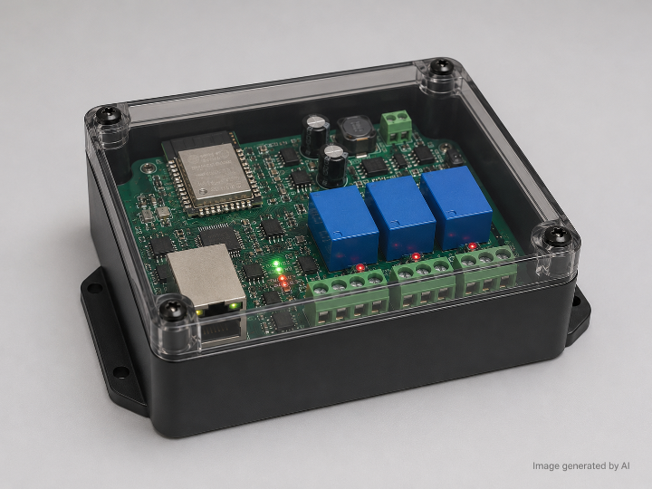
Portero Bot Hardware V2 is a custom PCB design for a wired IoT gate controller. Its purpose is to replace an earlier Raspberry Pi Pico, protoboard, and commercial relay-board arrangement with a dedicated PCB based on an ESP32-WROOM-32E, W5500 Ethernet controller, and three dry-contact relay outputs. The repository README describes the board as hardware and ESP32 firmware for the Claustro4 gate controller system, with Ethernet, relay control, a 9–24 V DC power input, MicroUSB programming, and OTA updates over Ethernet.
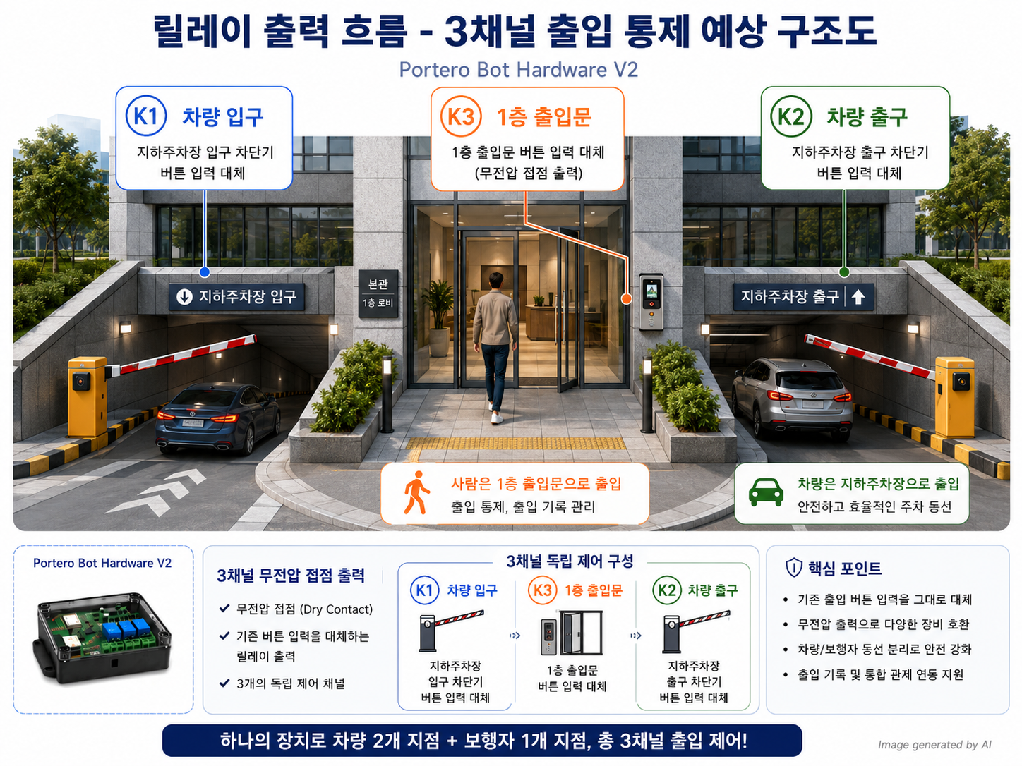
The system is not a general-purpose smart-home board. It is narrowly shaped around one physical task: receive an HTTP command over wired Ethernet and briefly close one of three relay contacts to simulate a button press on existing gate opener controllers. The exposed HTTP API includes three gate-opening endpoints, a health-check endpoint, and an OTA update endpoint.
What the Project Builds
The hardware design targets a 2-layer, 100 × 80 mm PCB intended for JLCPCB PCBA fabrication. The schematic reference document identifies the design as version 0.1, dated 2026-06-03, with suggested 2-layer PCB dimensions of 100 × 80 mm.
The intended board integrates the following blocks:
| Block | Main Parts | Role |
|---|---|---|
| MCU | ESP32-WROOM-32E | Runs HTTP API, relay logic, OTA handling |
| Ethernet | W5500 + HanRun HR911105A RJ45 | Provides wired Ethernet via SPI |
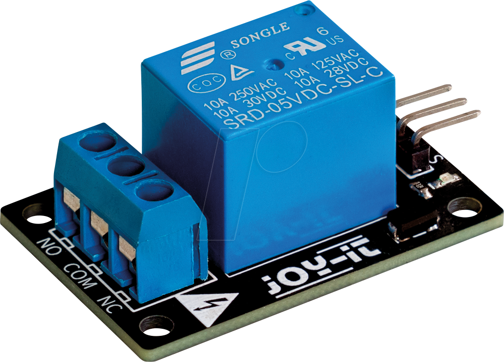
| Relay outputs | 3× SRD-05VDC-SL-C relays | Dry-contact outputs for gate opener inputs |
| Isolation / drive | PC817 optocouplers + 2N2222A transistors | Separates MCU GPIO from relay-drive stage |
| Power | 9–24 V DC input, MP2307DN buck, AMS1117-3.3 LDO | Generates 5 V relay rail and 3.3 V logic rail |
| USB debug | MicroUSB + CH340C | Initial flashing and serial debugging |
| Protection | SS34, SMAJ24CA TVS, PTC fuse | Input polarity, surge, and overcurrent protection |
The BOM in the schematic reference explicitly lists ESP32-WROOM-32E, W5500, CH340C, AMS1117-3.3, MP2307DN, HanRun HR911105A, three relays, three PC817 optocouplers, three 2N2222A drivers, flyback diodes, power-protection parts, and passive components.
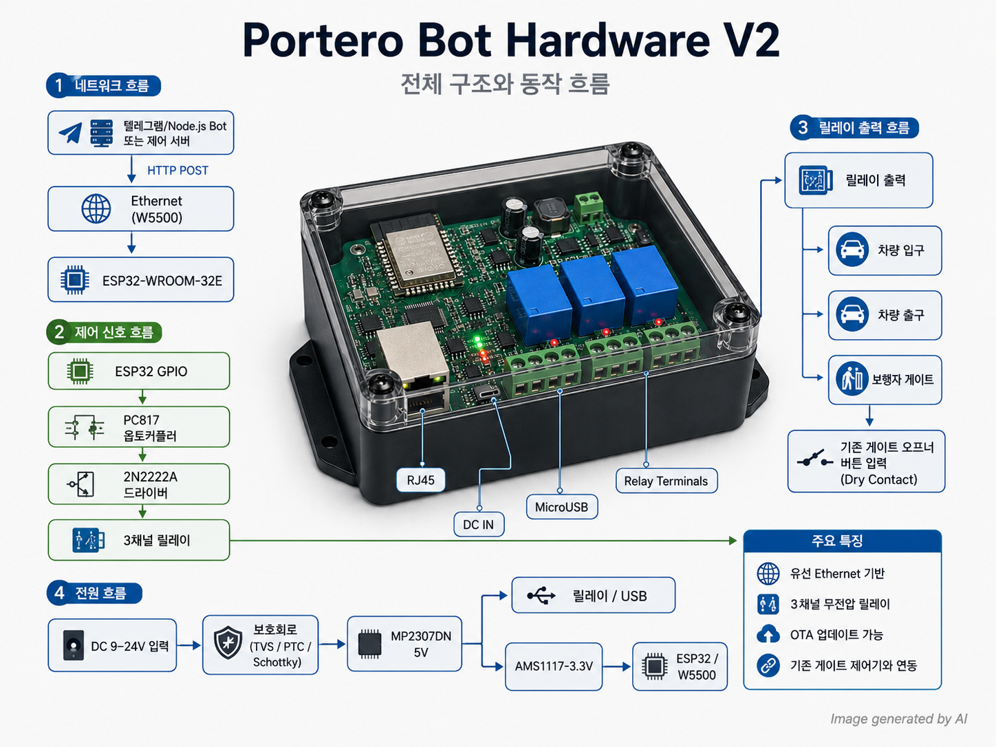
System Architecture
The architecture is simple and practical:
Telegram / Node.js bot or local control service
        |
        | HTTP request over Ethernet
        v
ESP32-WROOM-32E
        |
        | SPI
        v
W5500 Ethernet controller + RJ45 magjack
        |
        | GPIO relay commands
        v
PC817 optocoupler -> 2N2222A driver -> 5 V relay coil
        |
        v
Dry-contact NO/COM output to gate opener controller
The ESP32 communicates with the W5500 over SPI using GPIO18, GPIO23, GPIO19, GPIO5, GPIO26, and GPIO27 for SCLK, MOSI, MISO, chip select, interrupt, and reset respectively. The three relay channels are assigned to GPIO32, GPIO33, and GPIO25.
W5500 Role and TOE Relevance
The W5500 is the key networking component. In this design, the ESP32 does not rely on Wi-Fi for gate control. Instead, it uses the W5500 over SPI to provide a wired Ethernet interface through an RJ45 magjack. The repository’s schematic reference labels the W5500 as “SPI full-hardware TCP/IP,” and the official WIZnet product page describes W5500 as a hardwired Internet controller with an integrated TCP/IP stack, SPI interface, 10/100 Ethernet MAC/PHY, eight sockets, and internal packet buffer memory.
TOE judgment: yes, the project uses a WIZnet TOE-style Ethernet controller. This is not a pure MAC/PHY chip where the MCU must run the full TCP/IP stack itself. The W5500 includes a hardwired TCP/IP stack and exposes socket-style Ethernet handling through SPI. That is exactly the point of choosing W5500 for a small embedded controller whose job is to stay reachable and execute short control actions reliably.
Firmware Interface
The intended firmware interface is HTTP-based and compatible with an existing Node.js bot, so the external bot layer does not need to change. The documented endpoints are:
POST /abrir/vehicular_entrada
POST /abrir/vehicular_salida
POST /abrir/peatonal
GET  /healthz
POST /update
The schematic document further defines the three POST endpoints as 500 ms relay pulses, /healthz as a basic uptime response, and /update as an OTA firmware upload endpoint. The proposed firmware stack is PlatformIO + Arduino-ESP32, AsyncWebServer_ESP32_W5500, ESPAsyncWebServer, AsyncElegantOTA, and LittleFS for configuration.
Hardware Behavior
Each gate command activates one relay channel. The relay contacts are dry-contact NO/COM outputs, meaning the board is not intended to directly power the gate motor. It behaves like a remote button press across the opener controller’s input terminals. This is important: the board is a control-interface board, not a motor driver or high-power gate actuator. The relay section is documented as three identical channels using PC817 optocouplers, 2N2222A transistor drivers, 5 V relay coils, flyback diodes, and two-pin screw terminals.
Power Path
The board is designed for a 9–24 V DC barrel-jack input. The documented power path is:
9–24 V DC input
 -> SS34 Schottky diode
 -> SMAJ24CA TVS
 -> 1 A resettable PTC fuse
 -> MP2307DN buck converter
 -> 5 V rail
 -> AMS1117-3.3 LDO
 -> 3.3 V rail
The 5 V rail powers the relay coils, CH340C, and optocoupler collector side, while the 3.3 V rail powers the ESP32, W5500, and logic circuitry.
PCB Layout Intent
The layout guidance separates the board into a logic zone and a relay/output zone. ESP32, W5500, CH340C, and power supply belong to the logic area, while relays and gate screw terminals belong to the output area. The document also calls out critical routing rules: keep ESP32-to-W5500 SPI traces under about 5 cm, place the W5500 crystal close to the chip, route RJ45 differential pairs at 100 Ω differential impedance, and place decoupling capacitors close to each chip’s VCC pins.
Mechanically, the barrel jack, RJ45, MicroUSB, and relay screw terminals are intended to sit on PCB edges, while boot/reset buttons and the UART header should remain accessible for service.
Repository State and Production Readiness
The repository contains top-level folders for data, docs, firmware, hardware, kicad, and scripts. The README presents hardware/ as KiCad schematic, PCB layout, and Gerber files; firmware/ as PlatformIO ESP32 firmware; and docs/ as BOM, schematic reference, and Flux.ai prompt.
However, based on the visible GitHub directory listing, the firmware/ and hardware/ folders currently show only .gitkeep files, while the actual KiCad-related files appear under kicad/. The kicad/ directory contains KiCad project files, schematic and PCB files, ERC/DRC reports, and design-rule files.
The biggest caution is manufacturing readiness. The DRC report was generated on 2026-06-03 and reports 114 DRC violations. It includes drill-size violations, a malformed board outline with no Edge.Cuts layer, silkscreen warnings, and 180 unconnected pads.
That means the concept is strong, but the visible board files should not be treated as fabrication-ready without cleanup. A board sent to PCBA in this state would be risky. The project itself also lists pending work before fabrication, including confirming the KiCad designer, checking W5500 stock, confirming enclosure dimensions, choosing static IP versus DHCP reservation, bench-testing OTA before installation, and updating health-check tooling if the endpoint changes.
Practical Value
This project is valuable because it converts a prototype-style gate controller into a more maintainable embedded Ethernet controller. The key improvement is not “more features.” The key improvement is physical and operational stability: fewer jumper wires, a dedicated power path, a fixed wired network interface, field-updatable firmware, and dry-contact relay outputs that match how many gate opener controllers expect external buttons to behave.
Adoption Conditions
This design is suitable when:
| Condition | Fit |
|---|---|
| Wired Ethernet is available near the gate controller | Strong fit |
| The gate opener accepts dry-contact button input | Strong fit |
| Wi-Fi reliability is not acceptable | Strong fit |
| OTA updates are needed after enclosure installation | Good fit |
| Direct motor driving is required | Not suitable |
| Safety-certified access-control compliance is required | Needs additional validation |
| The current KiCad files are used without DRC cleanup | Not suitable |
Main Risks
| Risk | Why It Matters |
|---|---|
| DRC violations and unconnected pads | The current PCB may not fabricate or function correctly |
| Gate safety assumptions | Relay closure can trigger physical movement; interlocks remain external |
| Power input environment | Outdoor/garage gate environments may have surges and long cable noise |
| Enclosure fit | PCB edge connector placement depends on the final enclosure |
| Firmware absence in visible folder | The interface is documented, but implementation must still be verified |
| OTA security | /update must be protected, otherwise firmware upload becomes a serious attack surface |
External Summary
Portero Bot Hardware V2 is a focused embedded Ethernet relay controller for gate access systems. It combines ESP32 control logic, W5500 wired Ethernet, three optically isolated relay driver channels, and a protected 9–24 V power input into a custom PCB. Its design direction is sound for replacing a fragile protoboard-based controller, but the available KiCad state still requires engineering cleanup before production.
1. 프로젝트 개요
Portero Bot Hardware V2는 게이트, 출입문, 차량 출입구, 보행자 출입구 같은 물리적 개폐 장치를 네트워크 명령으로 제어하기 위한 전용 하드웨어 설계다. 저장소 README는 이 프로젝트를 Claustro4 게이트 컨트롤러 시스템을 위한 커스텀 PCB와 ESP32 펌웨어로 설명하며, 기존 Raspberry Pi Pico + 프로토보드 + 상용 릴레이 보드 구성을 전문적인 커스텀 PCB로 대체하는 것이 목적이라고 밝힌다.
핵심은 복잡한 자동문 장비 전체를 새로 만드는 것이 아니다. 기존 게이트 오프너 컨트롤러가 가진 “버튼 입력” 단자를 릴레이 접점으로 짧게 닫아, 사람이 버튼을 누른 것과 같은 신호를 만들어주는 장치다. 그러니까 이 보드는 모터 구동기가 아니라 네트워크 연결형 버튼 시뮬레이터에 가깝다.
2. 시스템이 해결하려는 문제
기존 구성은 Pico, 프로토보드, 상용 릴레이 보드 조합이었고, 이런 구성은 실험 단계에서는 빠르지만 장기간 설치 환경에서는 약점이 많다. 배선이 느슨해질 수 있고, 유지보수 시 어떤 선이 어떤 기능인지 추적하기 어렵고, 전원·릴레이·통신부가 하나의 설계 기준으로 정리되어 있지 않다.
이 프로젝트는 그 문제를 다음 방식으로 정리한다.
| 기존 문제 | 이 프로젝트의 대응 |
|---|---|
| 프로토보드 기반 임시 배선 | 2층 커스텀 PCB로 통합 |
| 상용 릴레이 보드 의존 | 3채널 릴레이 회로를 PCB에 직접 통합 |
| Wi-Fi 또는 불안정한 네트워크 가능성 | W5500 기반 유선 Ethernet 사용 |
| 현장 업데이트 불편 | Ethernet 기반 OTA 업데이트 고려 |
| 게이트별 제어선 혼재 | 차량 입구, 차량 출구, 보행자 게이트를 3개 릴레이 채널로 분리 |
이 설계 방향은 꽤 현실적이다. 게이트 제어처럼 “한 번 오동작하면 물리 장치가 움직이는” 분야에서는 화려한 기능보다 연결 안정성과 회로 단순성이 더 중요하다. 인간이야 복잡한 걸 좋아하다가 유지보수 때 후회하는 종족이지만, PCB는 그런 후회를 기록으로 남긴다.
3. 하드웨어 구성
문서 기준 목표 PCB는 100 × 80 mm, 2층 보드이며, JLCPCB PCBA 제작을 염두에 둔 설계다. 회로 문서에는 2026-06-03 날짜, 버전 0.1, 2층 PCB, JLCPCB PCBA 제작 조건이 명시되어 있다.
주요 부품은 다음과 같다.
| 영역 | 부품 | 역할 |
|---|---|---|
| 메인 MCU | ESP32-WROOM-32E | HTTP API 처리, 릴레이 제어, OTA 업데이트 |
| Ethernet | W5500 LQFP-48 | SPI 기반 유선 Ethernet 컨트롤러 |
| RJ45 | HanRun HR911105A | 마그네틱 내장 RJ45 커넥터 |
| USB-Serial | CH340C | 최초 플래싱 및 디버그 |
| 릴레이 | SRD-05VDC-SL-C ×3 | 게이트 오프너 입력 단자를 무전압 접점으로 단락 |
| 절연/드라이브 | PC817 ×3, 2N2222A ×3 | ESP32 GPIO와 릴레이 코일 구동부 분리 |
| 전원 | MP2307DN, AMS1117-3.3 | 9–24 V 입력을 5 V, 3.3 V로 변환 |
| 보호 | SS34, SMAJ24CA TVS, PTC fuse | 역극성, 서지, 과전류 보호 |
BOM에는 위 부품들이 LCSC 파트 번호와 함께 상세하게 정리되어 있다.


4. 동작 구조
전체 동작은 단순하다.
외부 Bot / Node.js 서비스
        |
        | HTTP POST 요청
        v
ESP32-WROOM-32E
        |
        | SPI
        v
W5500 Ethernet Controller
        |
        | GPIO 출력
        v
PC817 optocoupler
        |
        v
2N2222A relay driver
        |
        v
5 V relay coil
        |
        v
NO/COM dry contact
        |
        v
기존 게이트 오프너 버튼 입력
ESP32는 W5500과 SPI로 연결된다. 문서 기준 SPI 핀은 GPIO18(SCLK), GPIO23(MOSI), GPIO19(MISO), GPIO5(CS), GPIO26(INT), GPIO27(RST)이다. 릴레이는 GPIO32, GPIO33, GPIO25에 연결되어 차량 입구, 차량 출구, 보행자 게이트에 대응한다.
5. API 구조
README와 회로 문서에 기록된 HTTP API는 다음과 같다.
POST /abrir/vehicular_entrada
POST /abrir/vehicular_salida
POST /abrir/peatonal
GET  /healthz
POST /update
의미는 다음과 같이 해석할 수 있다.
| Endpoint | 동작 |
|---|---|
/abrir/vehicular_entrada | 차량 입구 릴레이 K1을 약 500 ms 동작 |
/abrir/vehicular_salida | 차량 출구 릴레이 K2를 약 500 ms 동작 |
/abrir/peatonal | 보행자 게이트 릴레이 K3을 약 500 ms 동작 |
/healthz | 장치 상태와 업타임 확인 |
/update | OTA 펌웨어 업로드 |
여기서 중요한 점은 API가 기존 Node.js bot과 호환되도록 설계되었다는 점이다. 즉, 외부 봇 로직은 유지하고, 아래쪽 물리 제어 하드웨어만 Pico/protoboard 구성에서 ESP32/W5500 PCB로 교체하려는 방향이다.
6. W5500 사용 의미와 TOE 적용 여부
이 프로젝트에서 W5500은 단순한 Ethernet PHY가 아니다. WIZnet 공식 설명 기준 W5500은 SPI로 연결되는 Hardwired Internet controller이며, TCP/IP 스택, 10/100 Ethernet MAC/PHY, 8개 소켓, 내부 버퍼 메모리를 포함한다.
따라서 이 프로젝트는 TOE 적용 프로젝트로 보는 것이 맞다.
단, 표현을 정확히 해야 한다. ESP32 안에 TOE가 들어간 것이 아니라, W5500 외부 Ethernet 컨트롤러가 TCP/IP 처리를 하드웨어로 담당하는 구조다.
이 선택의 의미는 다음과 같다.
| 관점 | 의미 |
|---|---|
| 안정성 | Wi-Fi 대신 유선 Ethernet으로 현장 연결 신뢰성을 높임 |
| MCU 부담 | TCP/IP 처리 일부를 W5500 하드웨어 스택에 맡김 |
| 구현 단순성 | ESP32는 HTTP API와 릴레이 제어 로직에 집중 |
| 현장성 | 게이트 제어처럼 고정 설치되는 장비에 유선 연결이 잘 맞음 |
추론임: 이 프로젝트가 W5500을 선택한 가장 큰 이유는 고속 대역폭이 아니라 현장 설치형 제어 장치에서 네트워크 연결을 단순하고 안정적으로 만들기 위한 것으로 보는 편이 타당하다. 근거는 README의 Ethernet 구성, W5500 SPI 사용, 기존 bot API 호환, OTA 업데이트 요구가 함께 나타나기 때문이다.
7. 릴레이 출력 구조
각 릴레이 채널은 동일한 구조를 반복한다. ESP32 GPIO가 PC817 optocoupler 입력을 구동하고, PC817 출력이 2N2222A 트랜지스터를 통해 5 V 릴레이 코일을 구동한다. 릴레이 코일에는 flyback diode가 붙고, 접점부는 NO/COM 형태로 2핀 터미널에 연결된다.
이 구조의 장점은 명확하다.
| 장점 | 설명 |
|---|---|
| 기존 게이트 오프너와 호환 | 버튼 입력 단자에 릴레이 접점을 병렬 연결하기 쉬움 |
| 전기적 분리 | MCU GPIO와 릴레이 코일 구동부를 분리 |
| 안전한 출력 개념 | 외부 장비에 전압을 밀어 넣는 것이 아니라 접점만 닫음 |
| 진단성 | 릴레이별 LED로 동작 상태 확인 가능 |
주의할 점도 있다. 릴레이가 “무전압 접점”이라고 해서 전체 시스템이 안전 인증을 받은 것은 아니다. 실제 설치 시 게이트 오프너 자체의 안전센서, 비상정지, 인터락, 낙하·끼임 방지 구조는 별도로 보장되어야 한다.
8. 전원 설계
전원 구조는 다음과 같다.
DC 9–24 V barrel jack
 -> SS34 Schottky diode
 -> SMAJ24CA TVS
 -> PTC 1 A fuse
 -> MP2307DN buck converter
 -> 5 V rail
 -> AMS1117-3.3 LDO
 -> 3.3 V rail
5 V rail은 릴레이 코일, CH340C, PC817 collector side에 사용되고, 3.3 V rail은 ESP32, W5500, 로직에 사용된다. 이 구성은 24 V 계열 현장 전원에서도 5 V 릴레이와 3.3 V 로직을 함께 쓰기 위한 일반적인 단계형 전원 구조다.
다만 MP2307DN buck, AMS1117 LDO, 릴레이 3채널, W5500, ESP32가 동시에 동작할 때의 발열과 전원 여유는 실제 PCB와 케이스 조건에서 검증해야 한다. 문서에는 추정 BOM과 회로 구조가 있지만, 열 측정이나 부하 테스트 결과가 보이지 않는다.
9. PCB 레이아웃 관점
문서의 레이아웃 지침은 꽤 현실적이다. 논리 영역에는 ESP32, W5500, CH340C, 전원부를 배치하고, 릴레이와 터미널 블록은 출력 영역으로 분리한다. SPI 라인은 5 cm 이하로 짧게 유지하고, W5500 crystal은 칩 가까이에 배치하며, RJ45 차동쌍은 100 Ω differential impedance로 라우팅하도록 되어 있다.
기구적으로는 barrel jack, RJ45, MicroUSB, 릴레이 터미널을 보드 외곽에 배치하고, BOOT/RESET 버튼과 UART 헤더는 케이스를 열었을 때 접근 가능해야 한다.
이 부분은 좋은 설계 방향이다. 특히 게이트 제어 장비는 설치 후 케이블 접근성이 중요하다. 커넥터를 보드 안쪽 아무 데나 던져놓으면, 나중에 드라이버 하나 들고 고생하는 인간 드라마가 시작된다.
10. 저장소 상태 평가
README는 hardware/, firmware/, docs/ 구조를 설명하고, firmware/를 PlatformIO ESP32 firmware로 소개한다.
하지만 실제 GitHub 디렉터리 표시 기준으로 firmware/와 hardware/ 폴더에는 현재 .gitkeep만 보인다. 반면 실제 KiCad 관련 파일들은 kicad/ 폴더에 들어 있으며, 여기에는 KiCad project, schematic, PCB, ERC/DRC report, design-rule 파일들이 포함되어 있다.
즉, 현 상태는 다음처럼 보는 것이 정확하다.
| 항목 | 상태 |
|---|---|
| 개념 정의 | 명확함 |
| BOM | 상세함 |
| 회로 블록 문서 | 상세함 |
| KiCad 파일 | 존재함 |
| firmware 실제 구현 | 현재 공개 폴더 기준 부족 |
| 제조 가능 상태 | DRC상 미완성 |
| 발표/소개 가치 | 있음 |
| 그대로 제작 가능성 | 낮음 |
11. 생산 전 위험 요소
가장 중요한 근거는 DRC report다. 보고서는 2026-06-03 생성되었고, 114개 DRC violation을 보고한다. 그 안에는 hole size out of range, Edge.Cuts layer 없음으로 인한 malformed outline, silkscreen clearance warning, solder mask 관련 warning 등이 포함되어 있다. 또한 별도로 180개 unconnected pads가 보고되어 있다.
이건 사소한 문서 문제가 아니다. 특히 invalid_outline과 unconnected pads는 제작 가능성과 동작 가능성에 직접 영향을 준다.
따라서 이 저장소는 “제작 직전 완성본”이라기보다는 설계 방향과 회로 구성은 잡혀 있으나, 제조 투입 전 PCB 정리가 필요한 상태로 보는 것이 맞다.
12. 기술적 장점
| 장점 | 설명 |
|---|---|
| 유선 Ethernet 기반 | 고정 설치형 게이트 제어에 적합 |
| W5500 TOE 구조 | MCU가 네트워크 처리 전체를 떠안지 않음 |
| 릴레이 dry contact | 기존 게이트 오프너 버튼 입력과 호환성 높음 |
| OTA 업데이트 | 현장 설치 후 펌웨어 유지보수 가능 |
| 보호회로 포함 | TVS, PTC, Schottky로 기본적인 입력 보호 고려 |
| BOM 구체성 | LCSC part number까지 포함되어 제작 검토가 쉬움 |
13. 한계와 보완 필요점
| 한계 | 보완 방향 |
|---|---|
| DRC violation 다수 | KiCad PCB 정리, Edge.Cuts 복구, drill rule 수정 |
| unconnected pads 존재 | netlist와 PCB routing 전면 검증 |
| firmware 폴더 내용 부족 | PlatformIO 프로젝트, 소스, 설정 파일 추가 필요 |
| OTA endpoint 보안 미정 | 인증 토큰, 네트워크 접근 제어, 업로드 제한 필요 |
| 릴레이 안전 검증 미확인 | 실제 게이트 오프너 입력 전압·전류 확인 필요 |
| 케이스 치수 미확정 | 커넥터 위치와 PCB 크기 재검증 필요 |
| 현장 서지/노이즈 | 긴 케이블 환경에서 EMI/ESD 추가 검토 필요 |
14. 적용 조건
이 프로젝트는 다음 조건에서 적합하다.
| 조건 | 평가 |
|---|---|
| 게이트 컨트롤러 근처에 Ethernet 포트가 있음 | 적합 |
| 기존 게이트가 버튼 입력/dry contact 입력을 지원함 | 적합 |
| 현장 Wi-Fi가 불안정함 | 적합 |
| 관리자용 Telegram/Node.js bot과 연동해야 함 | 적합 |
| 모터를 직접 구동해야 함 | 부적합 |
| 인증된 상용 출입통제 장비 수준의 안전 요구가 있음 | 추가 검증 필요 |
| 현재 KiCad 파일을 바로 발주하려 함 | 부적합 |
15. WIZnet 관점에서의 의미
이 프로젝트에서 W5500은 “인터넷이 되는 장식품”이 아니라 시스템의 신뢰성을 결정하는 핵심 부품이다. 게이트 제어는 데이터량이 많지 않다. 필요한 것은 높은 대역폭보다 명령 도달성, 고정 IP 운용 가능성, 유지보수성, 그리고 MCU 측 구현 부담 감소다.
W5500은 SPI 기반으로 ESP32에 붙고, TCP/IP 처리는 하드웨어 스택을 통해 처리한다. WIZnet 공식 페이지에서도 W5500이 integrated full TCP/IP stack, SPI, 10/100 Ethernet MAC/PHY, 8 sockets, internal memory를 제공한다고 설명한다.
따라서 이 프로젝트는 W5500의 장점이 비교적 잘 드러나는 사례다. “복잡한 네트워크 장비”가 아니라 “작은 MCU 기반 제어기가 안정적으로 Ethernet에 붙어야 하는 상황”에 W5500을 적용한 예다.
16. 발표용 핵심 정리
이 프로젝트는 게이트 제어용 임시 하드웨어를 ESP32와 W5500 기반의 전용 PCB로 정리하려는 설계다. 외부 Node.js 또는 Telegram bot은 HTTP API를 호출하고, ESP32는 해당 요청에 따라 세 개의 릴레이 중 하나를 500 ms 동안 동작시킨다. 릴레이는 기존 게이트 오프너의 버튼 입력을 흉내 내는 dry contact 방식이므로, 모터를 직접 구동하지 않는다.
기술적으로 가장 중요한 선택은 W5500이다. W5500은 SPI로 연결되는 Hardwired TCP/IP Ethernet controller이므로, ESP32가 Wi-Fi나 소프트웨어 TCP/IP 부담에 의존하지 않고 유선 Ethernet 기반 제어기로 동작할 수 있다. 다만 현재 저장소는 개념과 회로 문서는 충실하지만, DRC report에서 114개 위반과 180개 미연결 패드가 확인되므로 제작 전 KiCad 정리가 필수다.
17. 최종 판단
기술 방향: 좋음
회로 구성: 설계 의도는 명확함
W5500 적용성: 매우 적절함
TOE 적용 여부: 적용됨. W5500의 hardwired TCP/IP stack을 사용하는 구조
현재 완성도: 문서와 설계 초안은 충실하지만 제조-ready는 아님
큐레이션 가치: 높음
실제 제작 전 검증 필요성: 매우 높음
이 프로젝트의 가치는 “새로운 알고리즘”이 아니라 프로토타입을 현장 설치 가능한 전용 보드로 바꾸려는 실용적 전환에 있다. 단, 현재 KiCad 상태를 그대로 완제품처럼 소개하면 곤란하다. 설계 방향은 좋지만, DRC와 미연결 패드 문제를 해결해야 비로소 제작 가능한 하드웨어라고 말할 수 있다.
18. 저자 / 저장소 정보
- 저장소:
Willis75/portero-bot-hardware - 소유자: Willis75
- 공개 상태: Public
- GitHub 표시 기준 star 0, fork 0
- 관련 bot 저장소로
Willis75/Portero-bot-telegram이 README에 연결되어 있으나, 확인 시점에는 해당 링크 접근이 실패했다. 저장소가 삭제되었거나 비공개일 가능성이 있다.
-
portero-bot-hardware
