


ESPHome GPS/PPS Stratum-1 NTP Server on ESP32-S3 with a W5500 Ethernet Timestamping Path
A GPS 1 PPS pulse disciplines an ESP32-S3 clock to ~5 µs; the W5500 SPI Ethernet path is timestamped so LAN clients see 60–100 µs.

WIZnet - W5500
x 1

tiehfood/esphome-gps-pps-ntp-server
Overview
This project turns a Waveshare ESP32-S3-ETH board and a WD22UGRC GPS module into a Stratum-1 NTP server written entirely as ESPHome external components. A GPS module supplies UTC over NMEA and a 1 PPS pulse on a GPIO; the PPS edge disciplines the ESP32 system clock, and an NTP server running on the device serves that clock to the LAN through the board's W5500 Ethernet interface. Clock accuracy is about 5 µs against GPS, stable over 100 days, while client-visible accuracy is about 60–100 µs, limited by network path asymmetry rather than by the device.
The interesting part of the repository is the distance between those two numbers. It was originally 3.3 ms, and closing it meant pushing the server's receive and transmit timestamps down out of the application and into the W5500 SPI driver itself. The repository is published under GPL-3.0 and carries 17 stars and 7 forks, with its most recent push on 2026-09-04.
Hardware & Software Configuration
The hardware line in the repository reads: Waveshare ESP32-S3-ETH plus a WD22UGRC carrying a u-blox LEA-M8T timing receiver, with ESPHome on ESP-IDF as the framework. The board pairs an ESP32-S3 with a W5500 SPI Ethernet controller, and the GPS receiver contributes two signals that are treated very differently — NMEA sentences that say which second it is, and a 1 PPS edge on a GPIO that says exactly when that second starts.
The planning document kept in the repository records the working stack as ESPHome 2025.12.7 and ESP-IDF 5.5.1, a C++ ESPHome external component, lwIP BSD sockets, W5500 SPI Ethernet, and chrony on a LAN host used as the measurement instrument. The same document states a deliberate constraint for the build: no Wi-Fi components, W5500 Ethernet only. The ntp_server component repeats that constraint in its own source comment, noting the build is W5500-only with no Wi-Fi, and config_example.yaml selects the interface with a single line, type: W5500, at line 34.
Three components make up the firmware. gps_pps_time is the PPS-disciplined time source: its interrupt service routine only reads micros(), wall-clock time is reconstructed in the main loop, adjtime() corrects the clock every second, and whole-second errors are detected and corrected against NMEA. ntp_server is an RFC 5905 server that runs on a dedicated core-1 task, stamps T2 in the Ethernet driver's receive path, pre-corrects T3 from the measured transmit trigger, keeps client ARP entries warm, and drops requests while unsynchronised rather than serve a wrong time. ethernet is a fork of ESPHome's own Ethernet component that supplies the custom W5500 SPI driver the T2/T3 timestamping depends on, and that captures the W5500 interrupt edge in hardware via MCPWM.
Building is two commands:
source virtenv/bin/activate
esphome compile ntp_server.yaml
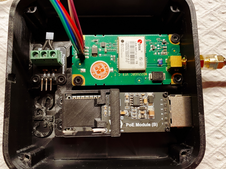
Antenna cable delay, about 5 ns per metre, is compensated in the receiver itself through UBX-CFG-TP5 rather than in firmware. A printable enclosure for the finished device is published on MakerWorld at https://makerworld.com/de/models/2774039-gps-box-clock-esphome-gps-pps-ntp-server.
Additional photos are available in the original repository: https://github.com/tiehfood/esphome-gps-pps-ntp-server
System Architecture
An NTP exchange uses four timestamps: the client's send (T1) and receive (T4), and the server's receive (T2) and transmit (T3). The architecture of this project follows directly from one observation about those four values — the server's timestamps need to be accurate, not early. However long the server takes between T2 and T3 cancels out in the client's calculation, but an error in when T2 or T3 is stamped does not cancel. It enters the client's computed offset at half its size, and the round-trip delay measurement is unaffected, so no client can detect or filter it. Serving latency is therefore treated here as a correctness problem rather than a performance one, and the software is laid out so that both server timestamps are taken as close to the wire as the hardware permits.
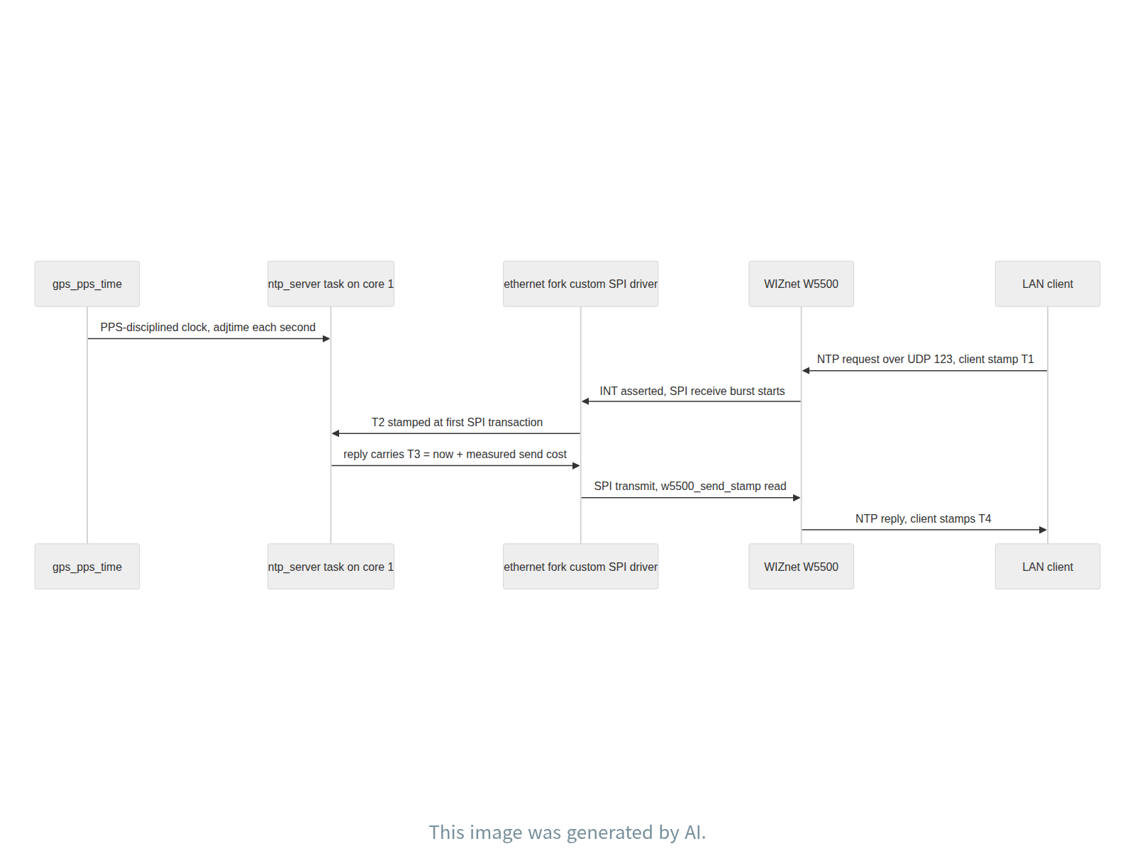
sequenceDiagram
    participant G as gps_pps_time
    participant S as ntp_server task on core 1
    participant D as ethernet fork custom SPI driver
    participant W as WIZnet W5500
    participant C as LAN client
    G->>S: PPS-disciplined clock, adjtime each second
    C->>W: NTP request over UDP 123, client stamp T1
    W->>D: INT asserted, SPI receive burst starts
    D->>S: T2 stamped at first SPI transaction
    S->>D: reply carries T3 = now + measured send cost
    D->>W: SPI transmit, w5500_send_stamp read
    W->>C: NTP reply, client stamps T4
Role of the WIZnet W5500
The W5500 is the entire path by which this clock reaches the network, and it is also where two of the four NTP timestamps are taken. The ESP32-S3 drives it over SPI through ESP-IDF's esp_eth SPI Ethernet support: the YAML key type: W5500 selects the SPI path, components/ethernet/__init__.py maps that string to EthernetType.ETHERNET_TYPE_W5500 at line 108 and lists it in SPI_ETHERNET_TYPES = ["W5500", "DM9051"] at line 122, and the C++ side compiles the W5500 branch under #if defined(USE_ETHERNET_SPI) && CONFIG_ETH_SPI_ETHERNET_W5500 before instantiating the MAC with esp_eth_mac_new_w5500(). The forked component installs a custom_spi_driver hook on that path, described in ethernet_component.h as existing so that NTP can observe the chip's traffic, and it insists that there must be exactly one spi_device_handle_t for the W5500 in the whole program — a second handle would re-route the chip-select pad to a different hardware CS signal and take the chip off the bus the driver thinks it owns.
Above that link, the protocol stack is ordinary and runs on the ESP32-S3: lwIP with BSD sockets, a UDP socket on port 123, and RFC 5905 packet construction in build_ntp_response_(). What is not ordinary is where the clock is read. On receive, the frame lands in the W5500, the chip asserts its interrupt, and the driver begins its SPI receive burst; T2 is stamped at the first SPI transaction of that burst, inside the W5500 driver's own task, at the point esp_eth hands the frame over — before the payload transfer and before the network stack sees anything. The driver delivers one frame at a time from that task, so the slot writes that carry the stamp never race. On transmit, ntp_server.cpp reads ethernet::w5500_send_stamp() immediately before and after the send call, so the actual instant the chip was told to transmit is recoverable rather than inferred.
The data flow, end to end, is therefore: the GPS receiver's 1 PPS edge and NMEA sentences discipline gps_pps_time; the core-1 ntp_server task reads that clock; a client request arrives from the LAN as an Ethernet frame through the W5500 and is stamped T2 in the SPI driver; the reply is built with a pre-corrected T3, handed to lwIP, and clocked out over SPI to the W5500, which puts it on the wire back to the client. The Ethernet controller is used as the MAC and PHY for raw frames in this design, with the IP and UDP layers running in lwIP on the MCU — which is precisely what makes the SPI-level timestamps meaningful, since the driver sees every transaction the chip performs.
Where the 3.3 ms went, and what replaced it
The repository lists each change with its measured effect. Serving from a dedicated FreeRTOS task instead of ESPHome's 16 ms main loop removed 3,300 µs. Stamping T2 in the Ethernet driver's receive path, before the network stack, took the device residual from 659 µs to 97 µs. Moving that stamp earlier, to the driver's Sn_RX_RSR read and therefore before the SPI payload transfer, was worth between 107 and 222 µs; moving it once more, to the first SPI transaction of the receive burst, was worth 53 ± 19 µs. Learning the T3 pre-correction from the measured transmit trigger removed 154 ± 20 µs. Clamping how far a single outlier can move the T3 estimate removed a 156 µs step that had lasted 8 samples. Priming ARP for recent clients removed a rare stall between T2 and T3, advertising root dispersion from a measured budget replaced 5 ms with 250 µs, and removing gettimeofday() from the PPS interrupt handler ended a pattern of 26 reboots per 149 days.
T3 deserves its own note, because it is a prediction rather than a reading: current time plus an estimate of the send cost. That estimate originally learned from how long sendto() took to return, but the packet is already in flight before the call returns, so the estimate ran long and every reply carried a T3 that was too late by roughly 180 µs. Because the custom SPI driver sees every transaction, the instant the chip is actually told to transmit is available, and the prediction error can be measured directly — it moved from a systematic −180 µs to zero ±23 µs.
The measurement work cost more time than the code. Unpaired before-and-after comparisons are not evidence on a routed path: two runs five minutes apart differed by 143 µs from network conditions alone, so every change is switchable at runtime and was measured in interleaved blocks. Regressing offset on delay looks like the correct way to control for network conditions, but delay is computed from T2 and T3, so controlling for it absorbs part of the effect — one change that measured as −12 ± 19 µs, indistinguishable from nothing, turned out to be −53 ± 19 µs once the known timestamp shift was added back before fitting. Sweeping the T3 filter's smoothing rate found the existing default was already best, with a settled error RMS of 9.85 µs against 11.12, 11.91 and 15.27 µs at other rates; the real weakness was a single 1251 µs outlier that shifted the estimate by 156 µs.
Bounding the error that remains
Three checks bound the residual without relying on the network behaving. The first is a hardware reference: the W5500 asserts an interrupt when a frame lands, and MCPWM capture timestamps that edge in hardware, on the same pin the Ethernet driver already uses, since the pin matrix allows both. The gap between that hardware edge and the driver's own stamp is 21 µs, and substituting the hardware edge for T2 measures +1.4 ± 14 µs — no gain, so it stays off and is kept as a diagnostic. The second is a packet-size sweep: from 48 to 1400 byte requests the offset grows 90 ns per byte, where two store-and-forward hops of wire time predict 80 ns per byte and SPI payload time leaking into T2 would give 240 or more. The third is simply that the T3 prediction error sits on zero.
What remains is roughly 60–100 µs of path asymmetry, the difference between outbound and return transit time. NTP cannot separate that from a genuine clock offset, and measuring below it requires a client on the same network segment. The accuracy budget behind the advertised figures is itemised: crystal drift measured at about 5 µs/s is handled by adjtime() every PPS, PPS interrupt latency of 0–10 ms is rare and is detected, compensated and spike-filtered, clock read granularity of 1–3 µs is constant and absorbed by the loop, antenna cable delay of about 5 ns/m is compensated via UBX-CFG-TP5, and the GPS PPS itself at about 30 ns RMS is the reference. The advertised root dispersion of 250 µs is the sum of measured terms: clock 50, T2 stamping 21, T3 prediction 23, and timestamp granularity 31.
Temperature is not modelled. The loop measures whatever the drift currently is and corrects it each second, and the residual is a steady 5 µs/s over seven days, but the board has only run between 43 and 46 °C — too narrow a range to fit a temperature coefficient, so any figure for 0 °C or 70 °C would come from a datasheet rather than from this device. For day-to-day health checks the repository names three signals: t3_error should sit at zero, int_lead near 20 µs, and arp_primes silent, with each reporting its own regression.
FAQ
Why is serving latency described as a correctness problem rather than a performance one?
Because the time the server spends between T2 and T3 cancels in the client's calculation, but an error in when those stamps are taken does not. It enters the client's computed offset at half its size and leaves the round-trip delay measurement unaffected, so no client can detect or filter it.
Why is client-visible accuracy 60–100 µs when the clock itself is about 5 µs?
The remainder is network path asymmetry — the difference between outbound and return transit time. NTP cannot separate that from a genuine clock offset, and measuring below it requires a client on the same network segment.
Is the MCPWM hardware capture of the W5500 interrupt used in production?
No. Using the hardware edge as T2 measures +1.4 ± 14 µs against the driver's own stamp, which is no gain, so it stays off and serves as a diagnostic. The gap between the two is 21 µs.
What does the server do while it is not synchronised to GPS?
The ntp_server component drops requests while unsynchronised rather than serve a wrong time.
How is the firmware built?
By activating the Python virtual environment and running esphome compile ntp_server.yaml, as shown in the repository's build section.
About the Author
The project is published by GitHub user tiehfood, who also maintains the printable enclosure model for the device on MakerWorld. The repository is licensed GPL-3.0, has 17 stars and 7 forks, and was last pushed on 2026-09-04. The author's support link is https://buymeacoffee.com/tiehfood. Beyond the firmware, the repository carries the measurement methodology and the planning document behind it, which is what makes the numbers above reproducible rather than merely claimed.
개요

이 프로젝트는 Waveshare ESP32-S3-ETH 보드와 WD22UGRC GPS 모듈을 ESPHome 외부 컴포넌트만으로 Stratum-1 NTP 서버로 만든 것이다. GPS 모듈이 NMEA로 UTC를 알려 주고 GPIO로 1 PPS 펄스를 내보내면, 그 PPS 에지가 ESP32의 시스템 클럭을 규율하고, 장치 위에서 도는 NTP 서버가 그 클럭을 보드의 W5500 이더넷 경로를 통해 LAN에 배포한다. 클럭 정확도는 GPS 대비 약 5 µs이며 100일 동안 안정적으로 유지됐고, 클라이언트가 실제로 보는 정확도는 약 60~100 µs로 장치가 아니라 네트워크 경로의 비대칭이 한계를 만든다.
저장소에서 흥미로운 부분은 이 두 숫자 사이의 거리다. 처음에는 그 차이가 3.3 ms였고, 그것을 좁히는 작업은 결국 서버의 수신·송신 타임스탬프를 애플리케이션 밖으로 끌어내려 W5500 SPI 드라이버 안에 집어넣는 일이었다. 저장소는 GPL-3.0으로 공개돼 있고 스타 17개, 포크 7개이며 마지막 푸시는 2026-09-04이다.
하드웨어·소프트웨어 구성
저장소가 밝힌 하드웨어는 Waveshare ESP32-S3-ETH와, u-blox LEA-M8T를 실은 WD22UGRC이며 프레임워크는 ESP-IDF 위의 ESPHome이다. 보드는 ESP32-S3와 W5500 SPI 이더넷 컨트롤러를 한 장에 얹은 구성이고, GPS 수신기가 내놓는 두 신호는 성격이 전혀 다르게 쓰인다. NMEA 문장은 "지금이 몇 초인가"를 알려 주고, GPIO로 들어오는 1 PPS 에지는 "그 초가 정확히 언제 시작하는가"를 알려 준다.
저장소에 함께 보관된 계획 문서는 작업 스택을 ESPHome 2025.12.7과 ESP-IDF 5.5.1, C++로 작성한 ESPHome 외부 컴포넌트, lwIP BSD 소켓, W5500 SPI 이더넷, 그리고 측정 기준으로 쓰는 LAN 호스트의 chrony로 기록한다. 같은 문서는 빌드의 의도적 제약도 못박는다. Wi-Fi 컴포넌트는 쓰지 않고 W5500 이더넷만 쓴다는 것이다. ntp_server 컴포넌트의 소스 주석도 이 빌드가 W5500 전용이며 Wi-Fi가 없다고 같은 말을 반복하고, config_example.yaml은 34번째 줄의 type: W5500 한 줄로 인터페이스를 선택한다.
펌웨어는 세 컴포넌트로 이뤄진다. gps_pps_time은 PPS로 규율되는 시각 소스로, 인터럽트 핸들러는 micros()만 읽고 실제 벽시계 시각은 메인 루프에서 재구성하며 매초 adjtime()으로 보정한다. 초 단위 오류는 NMEA와 대조해 검출하고 정정한다. ntp_server는 전용 core-1 태스크에서 도는 RFC 5905 서버로, 이더넷 드라이버의 수신 경로에서 T2를 찍고, 측정된 송신 트리거로부터 T3를 미리 보정하며, 최근 클라이언트의 ARP 항목을 따뜻하게 유지하고, 동기화되지 않은 동안에는 틀린 시각을 주는 대신 요청을 버린다. ethernet은 ESPHome 기본 이더넷 컴포넌트의 포크로, T2/T3 타임스탬프가 의존하는 커스텀 W5500 SPI 드라이버를 제공하고 W5500 인터럽트 에지를 MCPWM으로 하드웨어 캡처한다.
빌드는 두 줄이다.
source virtenv/bin/activate
esphome compile ntp_server.yaml
미터당 약 5 ns인 안테나 케이블 지연은 펌웨어가 아니라 수신기 쪽에서 UBX-CFG-TP5로 보정한다. 완성 장치의 출력용 케이스 모델은 MakerWorld에 공개돼 있다: https://makerworld.com/de/models/2774039-gps-box-clock-esphome-gps-pps-ntp-server
추가 사진은 원본 저장소에서 볼 수 있다: https://github.com/tiehfood/esphome-gps-pps-ntp-server
시스템 구조
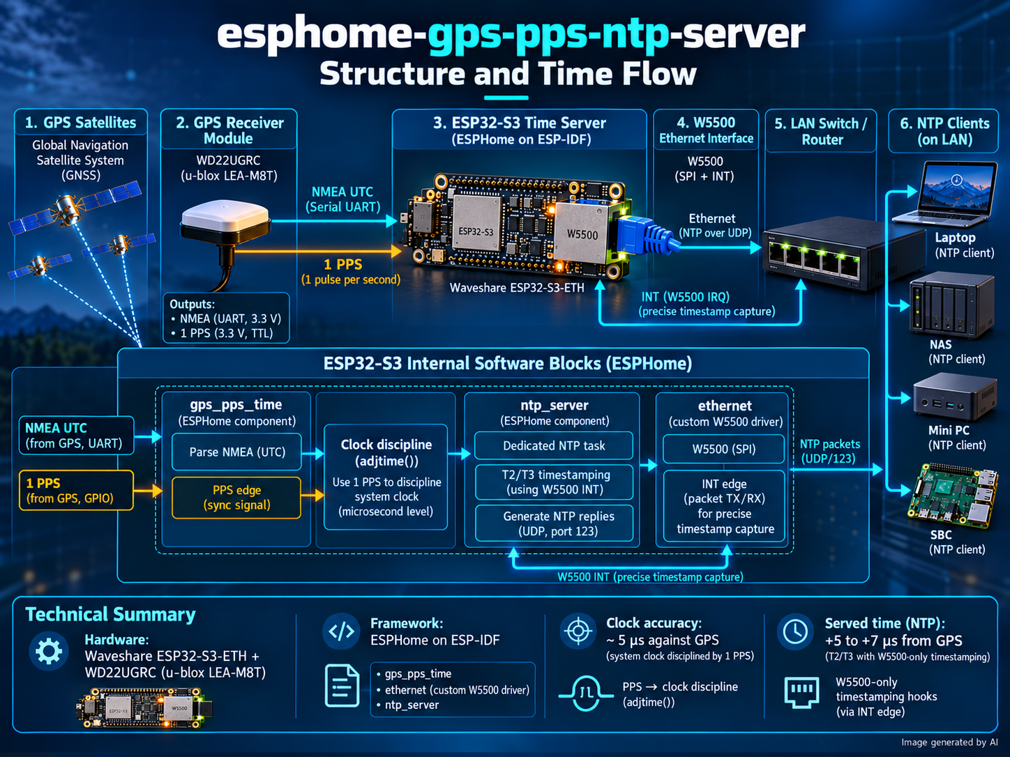
NTP 교환에는 네 개의 타임스탬프가 쓰인다. 클라이언트의 송신(T1)과 수신(T4), 서버의 수신(T2)과 송신(T3)이다. 이 프로젝트의 구조는 그 네 값에 대한 한 가지 관찰에서 곧바로 따라 나온다. 서버의 타임스탬프는 빨라야 하는 것이 아니라 정확해야 한다는 것이다. 서버가 T2와 T3 사이에 아무리 오래 걸려도 그 시간은 클라이언트의 계산에서 상쇄된다. 그러나 T2나 T3를 "언제" 찍었는가의 오차는 상쇄되지 않는다. 그 오차는 절반 크기로 클라이언트가 계산한 오프셋에 들어가고 왕복 지연 측정값은 영향을 받지 않으므로, 어떤 클라이언트도 그것을 검출하거나 걸러낼 수 없다. 그래서 이 저장소는 서빙 지연을 성능 문제가 아니라 정확성 문제로 다루며, 두 서버 타임스탬프를 하드웨어가 허락하는 한 가장 선로에 가까운 지점에서 찍도록 소프트웨어를 배치했다.
WIZnet W5500의 역할
W5500은 이 시계가 네트워크에 닿는 경로 전부이며, 동시에 네 타임스탬프 중 둘이 찍히는 지점이다. ESP32-S3는 ESP-IDF의 esp_eth SPI 이더넷 경로를 통해 SPI로 이 칩을 구동한다. YAML의 type: W5500 키가 SPI 경로를 고르고, components/ethernet/__init__.py가 108번째 줄에서 그 문자열을 EthernetType.ETHERNET_TYPE_W5500으로 매핑하며 122번째 줄의 SPI_ETHERNET_TYPES = ["W5500", "DM9051"]에 등록한다. C++ 쪽은 #if defined(USE_ETHERNET_SPI) && CONFIG_ETH_SPI_ETHERNET_W5500 아래에서 W5500 분기를 컴파일한 뒤 esp_eth_mac_new_w5500()으로 MAC을 만든다. 포크된 컴포넌트는 그 경로에 custom_spi_driver 훅을 설치하는데, ethernet_component.h의 주석은 그 훅이 존재하는 이유를 NTP가 칩의 트래픽을 관찰할 수 있게 하기 위해서라고 적는다. 같은 헤더는 프로그램 전체에서 W5500용 spi_device_handle_t가 정확히 하나뿐이어야 한다고 못박는다. 핸들이 하나 더 생기면 CS 패드가 다른 하드웨어 CS 신호로 재라우팅되면서, 드라이버가 자기 것이라고 믿는 버스에서 칩이 빠져나가기 때문이다.
그 링크 위의 프로토콜 스택은 평범하며 ESP32-S3에서 돈다. lwIP와 BSD 소켓, UDP 123번 포트, 그리고 build_ntp_response_()에서 만드는 RFC 5905 패킷이다. 평범하지 않은 것은 클럭을 읽는 위치다. 수신 시에는 프레임이 W5500에 들어오고 칩이 인터럽트를 올리며 드라이버가 SPI 수신 버스트를 시작하는데, T2는 그 버스트의 첫 SPI 트랜잭션에서, W5500 드라이버 자신의 태스크 안에서, esp_eth가 프레임을 넘겨주는 바로 그 지점에서 찍힌다. 페이로드 전송보다도 앞이고 네트워크 스택이 아무것도 보기 전이다. 그 드라이버는 자기 태스크에서 한 번에 한 프레임씩만 올려 주므로 스탬프를 담는 슬롯 쓰기가 경합하지 않는다. 송신 시에는 ntp_server.cpp가 전송 호출 직전과 직후에 ethernet::w5500_send_stamp()를 읽어, 칩에게 실제로 "보내라"고 말한 순간을 추정이 아니라 측정으로 확보한다.
데이터 흐름을 끝에서 끝까지 적으면 이렇다. GPS 수신기의 1 PPS 에지와 NMEA 문장이 gps_pps_time을 규율하고, core-1의 ntp_server 태스크가 그 클럭을 읽는다. LAN에서 온 클라이언트 요청은 이더넷 프레임으로 W5500을 지나 들어오며 SPI 드라이버에서 T2가 찍힌다. 응답은 미리 보정된 T3를 담아 만들어져 lwIP로 넘어가고, SPI로 W5500에 실려 나가 선로를 타고 클라이언트로 돌아간다. 이 설계에서 이더넷 컨트롤러는 원시 프레임을 다루는 MAC과 PHY로 쓰이고 IP·UDP 계층은 MCU의 lwIP에서 돌아간다. SPI 수준의 타임스탬프가 의미를 갖는 이유가 바로 이것으로, 드라이버가 칩이 수행하는 모든 트랜잭션을 볼 수 있기 때문이다.
3.3밀리초는 어디로 갔나
저장소는 각 변경과 그 측정 효과를 나란히 적어 둔다. ESPHome의 16 ms 메인 루프 대신 전용 FreeRTOS 태스크에서 서빙하자 3,300 µs가 사라졌다. 네트워크 스택보다 앞선 이더넷 드라이버 수신 경로에서 T2를 찍자 장치 잔차가 659 µs에서 97 µs로 내려갔다. 그 스탬프를 드라이버의 Sn_RX_RSR 읽기 시점으로, 즉 SPI 페이로드 전송보다 앞으로 옮기자 107~222 µs가 더 줄었고, 한 번 더 수신 버스트의 첫 SPI 트랜잭션으로 옮기자 53 ± 19 µs가 줄었다. 측정된 송신 트리거로부터 T3 사전 보정을 학습하게 하자 154 ± 20 µs가 줄었다. 이상치 하나가 T3 추정을 얼마나 끌 수 있는지 클램프하자 8 샘플 동안 지속되던 156 µs 계단이 사라졌다. 최근 클라이언트의 ARP를 미리 채우자 T2와 T3 사이에 드물게 나던 정체가 없어졌고, 루트 디스퍼전을 측정 기반 예산에서 산출하자 5 ms가 250 µs로 바뀌었으며, PPS 인터럽트 핸들러에서 gettimeofday()를 제거하자 149일에 26회씩 나던 재부팅이 끝났다.
T3는 따로 적어 둘 만하다. 그것은 읽은 값이 아니라 예측이기 때문이다. 현재 시각에 송신 비용 추정치를 더한 값인데, 그 추정치는 원래 sendto()가 반환하기까지 걸린 시간에서 학습했다. 그러나 그 호출이 반환되기 전에 패킷은 이미 날아가고 있으므로 추정치가 길게 잡혔고, 모든 응답이 대략 180 µs만큼 늦은 T3를 실어 보냈다. 커스텀 SPI 드라이버가 모든 트랜잭션을 보기 때문에 칩에게 실제로 송신을 지시한 순간을 알 수 있고, 따라서 예측 오차를 직접 측정할 수 있다. 그 값은 체계적인 −180 µs에서 0 ±23 µs로 옮겨 갔다.
측정 작업은 코드보다 더 많은 시간을 먹었다. 라우팅된 경로에서 짝지어지지 않은 전후 비교는 증거가 되지 않는다. 5분 간격으로 돌린 두 실행이 네트워크 상태만으로 143 µs 차이를 보였기 때문에, 모든 변경은 런타임에 켜고 끌 수 있게 만들어 블록을 교차시켜 측정했다. 오프셋을 지연에 회귀시키는 것은 네트워크 상태를 통제하는 옳은 방법처럼 보이지만, 지연 자체가 T2와 T3로부터 계산되므로 그것을 통제하면 효과의 일부까지 빨아들인다. 어떤 변경은 −12 ± 19 µs, 즉 아무것도 아닌 것과 구별되지 않게 측정됐지만, 이미 알고 있는 타임스탬프 이동분을 되돌려 넣고 적합하자 −53 ± 19 µs였다. T3 필터의 평활 계수를 훑어 본 결과는 기존 기본값이 이미 최선임을 보였다. 기본값에서 정착 오차 RMS가 9.85 µs였고 다른 계수에서는 11.12, 11.91, 15.27 µs였다. 약점은 계수가 아니라 추정치를 156 µs 움직인 단 하나의 1251 µs 이상치였다.
남은 오차를 어떻게 가뒀나
네트워크가 얌전하기를 기대하지 않는 세 가지 점검이 잔여 오차를 가둔다. 첫째는 하드웨어 기준이다. W5500은 프레임이 도착하면 인터럽트를 올리는데, MCPWM 캡처가 그 에지를 하드웨어로 타임스탬프한다. 핀 매트릭스가 두 기능을 동시에 허용하므로 이더넷 드라이버가 이미 쓰고 있는 같은 핀에서 가능하다. 그 하드웨어 에지와 드라이버 자체 스탬프의 간격은 21 µs이고, 하드웨어 에지를 T2로 쓰면 +1.4 ± 14 µs로 측정된다. 이득이 없으므로 평소에는 꺼 둔 채 진단용으로만 남겨 둔다. 둘째는 패킷 크기 스윕이다. 48바이트에서 1400바이트 요청까지 오프셋은 바이트당 90 ns씩 증가하는데, 저장 후 전달 방식 홉 두 개의 선로 시간은 바이트당 80 ns를 예측하고, SPI 페이로드 시간이 T2로 새어 들어오고 있다면 240 ns 이상이 나와야 한다. 셋째는 T3 예측 오차가 0에 앉아 있다는 사실 자체다.
남는 것은 대략 60100 µs의 경로 비대칭, 즉 나가는 길과 돌아오는 길의 전송 시간 차이다. NTP는 이것을 진짜 클럭 오프셋과 분리할 수 없고, 그보다 아래를 측정하려면 같은 네트워크 세그먼트에 클라이언트를 두어야 한다. 공개된 수치 뒤의 정확도 예산도 항목별로 적혀 있다. 약 5 µs/s로 측정된 크리스털 드리프트는 매 PPS마다 adjtime()으로 처리하고, 010 ms에 이르지만 드물게 나타나는 PPS 인터럽트 지연은 검출·보정하고 스파이크를 걸러낸다. 1~3 µs인 클럭 읽기 분해능은 일정하므로 루프가 흡수하고, 미터당 약 5 ns인 안테나 케이블 지연은 UBX-CFG-TP5로 보정하며, 약 30 ns RMS인 GPS PPS 자체가 기준이다. 광고하는 루트 디스퍼전 250 µs는 측정 항목의 합이다. 클럭 50, T2 스탬핑 21, T3 예측 23, 타임스탬프 분해능 31이다.
온도는 모델링하지 않는다. 루프는 지금의 드리프트가 얼마든 그것을 측정해 매초 보정하며, 잔차는 이레 동안 5 µs/s로 일정했다. 다만 보드가 지금까지 43~46 °C 사이에서만 동작했기 때문에 온도 계수를 적합하기에는 구간이 너무 좁고, 0 °C나 70 °C에 대한 수치를 적는다면 그것은 이 장치가 아니라 데이터시트에서 온 숫자가 된다. 일상적인 건강 점검을 위해 저장소는 세 신호를 지목한다. t3_error는 0에 있어야 하고, int_lead는 20 µs 근처여야 하며, arp_primes는 조용해야 한다. 각각은 자기 자신의 퇴행을 보고한다.
자주 묻는 질문
서빙 지연을 왜 성능이 아니라 정확성 문제라고 부르는가?
서버가 T2와 T3 사이에 쓴 시간은 클라이언트의 계산에서 상쇄되지만, 그 스탬프를 언제 찍었는가의 오차는 상쇄되지 않기 때문이다. 그 오차는 절반 크기로 클라이언트가 계산한 오프셋에 들어가고 왕복 지연 측정값은 그대로이므로, 어떤 클라이언트도 검출하거나 걸러낼 수 없다.
클럭 자체가 약 5 µs인데 클라이언트가 보는 정확도는 왜 60~100 µs인가?
나머지는 네트워크 경로의 비대칭, 즉 나가는 길과 돌아오는 길의 전송 시간 차이다. NTP는 그것을 진짜 클럭 오프셋과 분리할 수 없고, 그 아래를 측정하려면 같은 네트워크 세그먼트의 클라이언트가 필요하다.
W5500 인터럽트의 MCPWM 하드웨어 캡처는 실제 운용에 쓰이는가?
쓰이지 않는다. 하드웨어 에지를 T2로 썼을 때 드라이버 자체 스탬프 대비 +1.4 ± 14 µs로 측정돼 이득이 없기 때문에 꺼 둔 채 진단용으로만 둔다. 둘 사이의 간격은 21 µs다.
GPS에 동기화되지 않은 동안 서버는 어떻게 동작하는가?
ntp_server 컴포넌트는 동기화되지 않은 동안 틀린 시각을 주는 대신 요청을 버린다.
펌웨어는 어떻게 빌드하는가?
파이썬 가상환경을 활성화한 뒤 esphome compile ntp_server.yaml을 실행한다. 저장소의 빌드 절에 그대로 적혀 있다.
저자 소개
이 프로젝트는 GitHub 사용자 tiehfood가 공개했으며, 같은 저자가 장치의 출력용 케이스 모델도 MakerWorld에 올려 두었다. 저장소는 GPL-3.0 라이선스이고 스타 17개와 포크 7개를 기록하고 있으며 마지막 푸시는 2026-09-04이다. 저자의 후원 링크는 https://buymeacoffee.com/tiehfood이다. 저장소에는 펌웨어만이 아니라 측정 방법론과 그 뒤의 계획 문서가 함께 들어 있는데, 위의 숫자들이 주장에 그치지 않고 재현 가능한 값이 되는 근거가 그것이다.
-
GitHub Repository
Original project repository
