
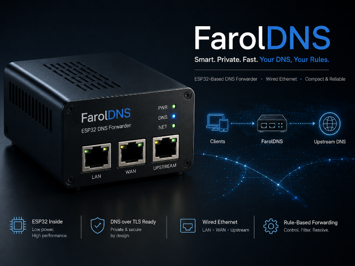
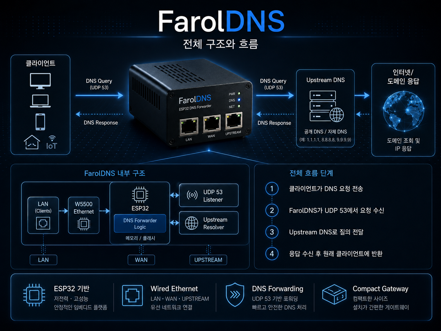
ESP32 DNS Forwarder PoC with W5500 Configuration Trace
FarolDNS is an ESP32-based DNS forwarding proof of concept that relays local UDP DNS queries to an upstream DNS server, while W5500 support appears only as a co
Espressif - ESP32
x 1

WIZnet - W5500
x 1
Title (EN)
ESP32 Modbus RTU REST API Gateway over Ethernet
One-Line Summary (EN)
An ESP32 gateway project that centralizes RS485/RS232 Modbus RTU access and exposes field devices through REST, WebSocket, web UI, and CLI.
Recommended Korean Category
산업용 Modbus 게이트웨이
Project Introduction
Modbus API Gateway is an ESP32-based open-source gateway project that connects RS485 and RS232 Modbus RTU devices to Ethernet-based software systems.
The core idea is to place one ESP32 gateway between upper-level software clients and serial Modbus field devices. Instead of allowing every client to access the same RS485 or RS232 bus directly, the gateway becomes the controlled communication point. External clients such as Node-RED, SCADA software, HMI panels, browser tools, scripts, or automation servers communicate with the gateway through HTTP REST API calls, while the gateway handles the actual Modbus RTU transactions on the serial side.
This makes the project more than a basic Modbus reading example. It is an API-oriented gateway implementation for fieldbus access. The lower layer remains Modbus RTU, with its serial timing and bus ownership constraints, but the upper layer becomes easier to integrate with modern software systems that already understand HTTP and JSON.
The project is best understood as a Modbus RTU REST API gateway project, not as a simple Modbus TCP-to-RTU bridge. Its main value is centralizing serial fieldbus access and exposing it through web-friendly interfaces.
System Structure and Flow
The system is organized around one central ESP32 gateway.
Node-RED / SCADA / HMI / Browser / Script
                |
                | HTTP REST / WebSocket over Ethernet
                v
        ESP32 Modbus API Gateway
                |
                | UART
                v
        RS485 / RS232 Transceiver
                |
                v
        Modbus RTU Devices
The important architectural point is bus ownership. Modbus RTU is a serial protocol, and only one master should control the bus at a time. When several systems compete for direct access, each system must handle timing, CRC, retries, timeouts, and error behavior on its own. That duplicates logic and increases the risk of collisions.
With this gateway project, upper systems do not speak directly to the serial bus. They send HTTP requests to the ESP32. The gateway interprets those requests, selects the configured Modbus interface, performs the RTU transaction, and returns a JSON response.
A typical holding-register read follows this flow.
1. A client sends an HTTP GET request.
2. The API layer parses the endpoint and parameters.
3. The service layer validates the interface, slave address, and register range.
4. The Modbus layer performs one RTU transaction on the selected UART interface.
5. The field device responds over RS485 or RS232.
6. The gateway converts the result into JSON.
7. The response is returned to the client.
8. WebSocket updates can be used for monitoring views.
This structure keeps the serial bus controlled while making the upper interface software-friendly. It does not make Modbus RTU parallel or free from timing constraints. It simply moves those constraints into one gateway implementation instead of scattering them across every client.
W5500 / WIZnet and TOE Position
The project supports wired Ethernet through LAN8720 or W5500.
LAN8720 is the RMII Ethernet option. W5500 is the SPI Ethernet option. In an ESP32 design where SPI Ethernet is easier to route or integrate than RMII Ethernet, W5500 becomes a practical hardware choice. In this project, however, W5500 is one supported Ethernet path, not the only identity of the project.
The W5500 role should be described carefully.
W5500 itself is a WIZnet Ethernet controller with a hardwired TCP/IP stack. However, this project integrates W5500 through the ESP-IDF Ethernet driver model. The firmware configures SPI, creates the W5500 MAC and PHY driver objects, installs the Ethernet driver, attaches it to esp_netif, and starts the Ethernet interface.
The application-facing path is therefore:
ESP32 application
        |
ESP-IDF HTTP server / WebSocket / network APIs
        |
esp_netif + lwIP
        |
esp_eth
        |
W5500 SPI Ethernet driver
        |
W5500 Ethernet hardware
        |
Ethernet LAN
The project uses W5500 as a SPI Ethernet interface under ESP-IDF/lwIP. It does not appear to control W5500 hardware sockets directly from the application layer. This distinction matters because “W5500 is supported” and “the firmware directly uses W5500 hardware TCP/IP socket offload” are not the same claim.
The most accurate summary is:
W5500 is used as a selectable SPI Ethernet interface.
The confirmed network path is ESP-IDF esp_eth / esp_netif / lwIP based.
This project should not be described as a direct W5500 hardware-socket TOE example.
Implementation Paths and Source Structure
The active implementation is an ESP-IDF firmware project organized under firmware/main.
The PlatformIO configuration points to firmware/main as the ESP-IDF main component directory. The main component then registers the firmware entry point and the functional modules together. This confirms that the project is not just a loose set of examples. It is structured as a gateway firmware with separate areas for core initialization, Modbus handling, storage, service dispatch, API routes, OTA, Wi-Fi management, and frontend assets.
A simplified source view is:
firmware/main/
├── main.c
├── core/
│   ├── config.c/.h
│   ├── ethernet.c/.h
│   ├── wifi_manager.c/.h
│   └── serial_cli.c/.h
├── modbus/
│   ├── modbus_manager.c/.h
│   ├── interface.c/.h
│   ├── sw_uart.c
│   └── mb_rtu_sw.c
├── storage/
│   ├── config_store.c/.h
│   └── register_cache.c/.h
├── service/
│   └── gateway_service.c/.h
├── api/
│   ├── server.c/.h
│   ├── ws_handler.c/.h
│   └── routes/
│       ├── coils.c
│       ├── discrete.c
│       ├── holding_regs.c
│       ├── input_regs.c
│       ├── interfaces.c
│       ├── system.c
│       ├── ota.c
│       ├── wifi.c
│       ├── mgmt.c
│       └── cache.c
└── ota/
    └── ota_manager.c/.h
The firmware starts from app_main(). The startup order shows the intended runtime shape: persistent configuration is loaded, the serial CLI starts early, Ethernet is initialized, Wi-Fi is initialized, the register cache is prepared, Modbus interfaces are initialized, and the HTTP/WebSocket API server is started.
This order is meaningful. Configuration must exist before interfaces are created. Network initialization is separated from Modbus initialization. Ethernet or Modbus initialization failure is treated as non-fatal in the boot path, which fits a gateway project that may still expose configuration or management functions even when field wiring or Ethernet hardware is not available.
The architecture is separated into layers.
Ethernet clients
        |
API layer
        |
Service layer
        |
+-------------------+
|                   |
Modbus layer     Storage layer
        |
Hardware layer
The API layer translates HTTP requests into internal requests and converts internal results into JSON. The service layer dispatches Modbus operations and manages cache-related behavior. The Modbus layer performs RTU transactions through UART interfaces. The storage layer persists configuration and recent values. The frontend communicates through the API layer rather than bypassing it.
This layered structure makes the project easier to explain than a single-file Modbus example. The communication path is visible from HTTP endpoint down to UART transaction.
REST API and Modbus Mapping
The REST API maps standard Modbus operations to HTTP endpoints.
Base URL:
http://{gateway-ip}/api/v1
The {key} part can be either a numeric interface ID or a human-readable alias such as floor1 or pumpestation. This matters in real field maintenance because readable aliases are easier to understand than numeric-only interface references.
Read operations include:
| Modbus operation | HTTP method | Endpoint style |
|---|---|---|
| Read coils | GET | /interfaces/{key}/slaves/{sid}/coils?start={n}&count={n} |
| Read discrete inputs | GET | /interfaces/{key}/slaves/{sid}/discrete-inputs?start={n}&count={n} |
| Read holding registers | GET | /interfaces/{key}/slaves/{sid}/holding-registers?start={n}&count={n} |
| Read input registers | GET | /interfaces/{key}/slaves/{sid}/input-registers?start={n}&count={n} |
Write operations include:
| Modbus operation | HTTP method | Endpoint style |
|---|---|---|
| Write single coil | PUT | /interfaces/{key}/slaves/{sid}/coils/{addr} |
| Write single holding register | PUT | /interfaces/{key}/slaves/{sid}/holding-registers/{addr} |
| Write multiple coils | PUT | /interfaces/{key}/slaves/{sid}/coils?start={n} |
| Write multiple holding registers | PUT | /interfaces/{key}/slaves/{sid}/holding-registers?start={n} |
The interface administration endpoints allow clients to list, create, read, update, and delete Modbus interfaces. Each interface can carry practical serial settings such as type, UART mode, Modbus role, slave address, baud rate, parity, stop bits, timeout, GPIO pins, and enabled state.
This design makes the project closer to a small fieldbus management gateway implementation than a hardcoded “read one register” demo.
Usage Perspective
This project is best understood as an embedded API gateway project for legacy serial industrial devices.
It fits environments where field devices already speak Modbus RTU, but the upper system prefers HTTP, JSON, web dashboards, automation scripts, or Node-RED flows. It can also help when several software systems need access to the same physical fieldbus but should not all become direct Modbus masters.
Good application contexts include:
| Context | How the project fits |
|---|---|
| Node-RED automation | HTTP request nodes can access Modbus data without a serial Modbus node |
| Small SCADA integration | SCADA-side tooling can query a gateway API rather than own the serial bus |
| Equipment monitoring | Sensors, meters, inverters, and controllers can be exposed through JSON endpoints |
| Test benches | Engineers can read and write registers through simple HTTP calls |
| Legacy modernization | RS485/RS232 devices can be connected to web-native systems |
| Local maintenance UI | Interface configuration and monitoring can be handled through the web interface direction |
The central engineering boundary is still the serial bus. REST API access does not make Modbus RTU parallel. The gateway must serialize access per UART interface, and timing still matters. HTTP makes the upper side easier to use; it does not remove the electrical and timing rules underneath.
The project also includes Wi-Fi management routes and OTA-related routes, but the main identity remains Ethernet-based Modbus RTU access through an ESP32 gateway. The wired Ethernet option is especially important for installations where stable connectivity matters more than wireless convenience.
The highest-risk practical area is write access. Coil and holding-register writes can affect real equipment behavior. Any deployment based on this kind of gateway should treat network exposure, authentication, segmentation, and write permissions as part of the system boundary.
Frequently Asked Questions
What is this project?
It is an ESP32-based gateway project that exposes RS485/RS232 Modbus RTU field devices through an Ethernet REST API.
What problem does it solve?
It prevents multiple clients from competing directly on the same serial Modbus bus by making the ESP32 gateway the central access point.
Is it the same as a Modbus TCP to RTU gateway?
No. A typical Modbus TCP to RTU gateway serves Modbus TCP clients. This project exposes Modbus operations as HTTP REST endpoints, which makes it easier to integrate with web tools, scripts, dashboards, and automation systems.
Does it use W5500?
Yes. W5500 is supported as a SPI Ethernet option alongside LAN8720.
Does it directly use W5500 TCP/IP offload sockets?
The confirmed implementation follows the ESP-IDF Ethernet driver path with esp_eth, esp_netif, and lwIP. It is better described as W5500 used as a SPI Ethernet interface, not as direct application control of W5500 hardware sockets.
Is it an Arduino project or an ESP-IDF project?
The active firmware path is ESP-IDF. The build configuration points to firmware/main, and the main component registers ESP-IDF source files including main.c.
What clients can use it?
Any client that can send HTTP requests can use it: browser tools, curl, Node-RED, Python, JavaScript, SCADA tooling, or automation servers.
Is it a finished industrial product?
It is an open-source embedded gateway project with a structured firmware architecture. It shows a practical gateway concept and implementation path, but deployment should still consider network security, field wiring, timing behavior, and reliability requirements.
ESP32 기반 Modbus RTU REST API 게이트웨이 프로젝트
1. 프로젝트 소개
이 프로젝트는 ESP32를 중심으로 RS485/RS232 Modbus RTU 장비를 Ethernet 기반 REST API로 연결하는 산업용 통신 게이트웨이 구현입니다.
핵심은 단순한 Modbus 변환이 아닙니다. 여러 상위 시스템이 같은 RS485 버스에 직접 접근하지 않도록 하고, ESP32 게이트웨이를 단일 접근 지점으로 둔 뒤, 외부 클라이언트는 HTTP REST API로 접근하게 만드는 구조입니다.
즉, 이 프로젝트는 다음과 같은 게이트웨이 구조로 볼 수 있습니다.
현장 Modbus RTU 장비
        |
RS485 / RS232
        |
ESP32 Modbus API Gateway
        |
Ethernet REST API / WebSocket / Web UI / CLI
        |
Node-RED / SCADA / HMI / Browser / Script
Modbus RTU는 여전히 현장에서 널리 사용되지만, 직렬 통신이라는 특성 때문에 여러 시스템이 동시에 접근하기 어렵습니다. 이 프로젝트는 그 직렬 버스의 접근권을 ESP32 게이트웨이 하나로 모으고, 상위 시스템에는 HTTP와 JSON으로 다루기 쉬운 인터페이스를 제공합니다.
따라서 이 프로젝트의 성격은 “Modbus TCP 변환기”보다는 “Modbus RTU를 REST API로 중앙집중화하는 임베디드 API 게이트웨이 프로젝트”에 가깝습니다.
2. 구조와 흐름
전체 구조는 ESP32 게이트웨이를 중심으로 왼쪽에는 Ethernet 클라이언트, 오른쪽에는 RS485/RS232 기반 현장 장비가 연결되는 형태입니다.
[상위 클라이언트]
Node-RED / SCADA / HMI / Browser / Python Script
        |
        | HTTP REST / WebSocket
        v
[ESP32 Modbus API Gateway]
        |
        | UART
        v
[RS485 / RS232 Transceiver]
        |
        v
[Modbus RTU Slave Devices]
기존 방식에서는 Node-RED, SCADA, HMI, 데이터로거 같은 여러 시스템이 각자 Modbus 통신을 구현하고 같은 RS485 버스에 접근해야 했습니다. 이 경우 각 시스템이 timing, CRC, timeout, retry, 에러 처리를 따로 관리해야 하고, 버스 접근 충돌 가능성도 커집니다.
이 프로젝트는 ESP32를 유일한 접근 지점으로 둡니다. 클라이언트는 REST API로 요청을 보내고, ESP32는 해당 요청을 Modbus RTU transaction으로 변환해 현장 장비와 통신합니다. 응답은 다시 JSON 형태로 정리되어 클라이언트에게 반환됩니다.
Holding register를 읽는 흐름은 다음과 같이 볼 수 있습니다.
1. 클라이언트가 HTTP GET 요청을 보냅니다.
2. API 계층이 endpoint와 parameter를 해석합니다.
3. Service 계층이 대상 interface, slave address, register 범위를 확인합니다.
4. Modbus 계층이 선택된 UART interface에서 RTU 요청을 수행합니다.
5. RS485/RS232 현장 장비가 응답합니다.
6. Gateway가 응답을 JSON으로 변환합니다.
7. HTTP response가 클라이언트로 반환됩니다.
8. 필요한 경우 WebSocket으로 모니터링 화면에 변경 사항을 전달합니다.
여기서 중요한 점은 API가 현대적이어도 아래쪽 통신은 여전히 직렬 버스라는 점입니다. REST API는 상위 시스템의 접근성을 높이지만, RS485/RS232의 timing과 bus ownership 문제를 사라지게 만들지는 않습니다. 이 프로젝트의 가치는 그 물리적 제약을 API Gateway 구조 안에서 통제하려는 데 있습니다.
3. W5500 / WIZnet과 TOE 관점
이 프로젝트는 Ethernet 하드웨어로 LAN8720 또는 W5500을 지원합니다.
LAN8720은 RMII 기반 Ethernet PHY이고, W5500은 SPI 기반 Ethernet controller입니다. ESP32 설계에서 RMII 배선이 부담스럽거나 SPI 기반 Ethernet 구성이 더 적합한 경우 W5500은 실용적인 선택지가 됩니다.
다만 W5500의 역할은 정확히 나눠서 설명해야 합니다.
W5500 칩 자체는 Hardwired TCP/IP stack을 내장한 Ethernet controller입니다. 그러나 이 프로젝트의 코드에서는 W5500을 ESP-IDF Ethernet driver 경로로 초기화합니다. 코드 흐름은 SPI bus 구성, ETH_W5500_DEFAULT_CONFIG, W5500 MAC/PHY driver 생성, Ethernet driver install, esp_netif_attach, esp_eth_start로 이어집니다.
따라서 이 프로젝트의 네트워크 구조는 다음과 같이 보는 것이 자연스럽습니다.
ESP32 application
        |
ESP-IDF HTTP server / WebSocket / network API
        |
esp_netif + lwIP
        |
esp_eth
        |
W5500 SPI Ethernet driver
        |
W5500 Ethernet hardware
        |
Ethernet LAN
즉, W5500은 실제로 Ethernet 인터페이스로 사용됩니다. 하지만 애플리케이션이 W5500의 하드웨어 socket command나 register 기반 TCP/IP API를 직접 제어하는 구조로 보기는 어렵습니다.
정리하면 다음과 같습니다.
| 항목 | 판단 |
|---|---|
| W5500 지원 여부 | 지원합니다 |
| W5500 필수 여부 | 필수는 아닙니다. LAN8720도 지원합니다 |
| W5500의 역할 | ESP32에 SPI 기반 유선 Ethernet interface를 제공합니다 |
| TOE 직접 사용 여부 | 직접적인 W5500 hardware socket 제어 구조로 보기는 어렵습니다 |
| 네트워크 처리 경로 | ESP-IDF esp_eth, esp_netif, lwIP 기반으로 보는 것이 적절합니다 |
이 구분은 중요합니다. W5500이 들어갔다고 해서 곧바로 “W5500 TOE를 직접 사용했다”고 쓰면 실제 구현과 어긋날 수 있습니다. 이 프로젝트에서는 W5500을 유선 Ethernet 연결을 위한 하드웨어 인터페이스로 설명하는 편이 정확합니다.
4. 구현 경로와 소스 구성
현재 중심 구현은 ESP-IDF 기반 firmware입니다.
platformio.ini는 firmware/main을 ESP-IDF main component 경로로 지정하고, 실제 main component는 main.c, Ethernet, Wi-Fi, Modbus, storage, service, API route, WebSocket, OTA 관련 소스를 함께 빌드 대상으로 등록합니다.
실행 진입점은 app_main()입니다. 초기화 흐름은 다음과 같이 구성됩니다.
NVS 초기화
        |
설정 로드
        |
Serial CLI 시작
        |
Ethernet 초기화
        |
Wi-Fi 초기화
        |
Register cache 초기화
        |
Modbus interface 초기화
        |
HTTP / WebSocket API server 시작
이 순서는 프로젝트의 성격을 잘 보여줍니다. 설정이 먼저 로드되고, 네트워크와 Modbus 계층이 초기화된 뒤, 마지막에 API server가 올라갑니다. 또한 Ethernet이나 Modbus 초기화 실패가 곧바로 전체 부팅 중단으로 이어지지 않는 흐름도 보입니다. 이는 현장 배선이나 네트워크 상태가 항상 완벽하지 않을 수 있는 gateway 프로젝트의 특성과 맞습니다.
소스 구조는 다음과 같은 역할 분리로 이해할 수 있습니다.
| 영역 | 역할 |
|---|---|
core | 설정 구조, Ethernet 초기화, Wi-Fi 관리, UART CLI |
modbus | Modbus manager, interface 처리, HW/SW UART, RTU 처리 |
storage | NVS 설정 저장, SPIFFS register cache |
service | REST 요청을 Modbus 호출로 연결하는 dispatch 계층 |
api | HTTP server, REST route, WebSocket handler |
ota | firmware/frontend update 흐름 |
frontend | Web UI 정적 파일과 JavaScript API 호출 |
아키텍처 문서에서도 API 계층, service 계층, Modbus 계층, storage 계층, hardware 계층이 분리되어 있습니다. 이 구조 덕분에 프로젝트를 설명할 때 “ESP32가 Modbus를 읽는다”에서 끝나지 않고, “HTTP 요청이 어떻게 Modbus RTU transaction으로 내려가고 다시 JSON 응답으로 올라오는지”를 계층적으로 설명할 수 있습니다.
5. 적용 관점
이 프로젝트는 기존 Modbus RTU 장비를 HTTP/JSON 기반 시스템에 연결하려는 상황에 잘 맞습니다.
대표적인 적용 장면은 다음과 같습니다.
| 적용 분야 | 의미 |
|---|---|
| Node-RED 자동화 | Modbus node 없이 HTTP request node로 register 값을 읽을 수 있습니다 |
| 소규모 SCADA 연동 | SCADA나 자동화 서버가 직접 RS485 포트를 소유하지 않아도 됩니다 |
| 설비 모니터링 | 전력계, 센서, 인버터, 컨트롤러 값을 REST API로 노출할 수 있습니다 |
| 테스트 벤치 | curl이나 Python으로 Modbus register 읽기/쓰기 테스트가 쉬워집니다 |
| 레거시 장비 연결 | RS485/RS232 장비를 웹 기반 시스템에 붙이는 중간 계층으로 쓸 수 있습니다 |
| 현장 설정 관리 | Web UI나 CLI를 통해 interface 설정을 조정하는 흐름을 만들 수 있습니다 |
이 프로젝트의 핵심 장점은 상위 시스템을 단순하게 만든다는 점입니다. 상위 시스템은 HTTP client만 있으면 되고, Modbus timing과 직렬 포트 관리는 gateway가 맡습니다.
다만 현장 적용 관점에서 가장 크게 봐야 할 지점은 쓰기 API입니다. Coil이나 holding register에 대한 쓰기 요청은 실제 장비 동작에 영향을 줄 수 있습니다. 따라서 이 구조를 실제 설비에 연결할 때는 네트워크 접근 범위, 인증, 방화벽, 내부망 분리, 쓰기 권한 정책을 함께 봐야 합니다.
또한 Software UART는 interface 수를 늘릴 수 있지만, 고속·고신뢰 Modbus 통신에서는 hardware UART와 같은 성격으로 보면 안 됩니다. 이 프로젝트의 구조는 다중 interface gateway 개념을 보여주지만, 각 현장 장비의 baud rate, 거리, 배선 품질, 통신 주기, timeout 조건은 여전히 중요합니다.
6. 자주 묻는 질문
이 프로젝트는 무엇인가요?
ESP32가 RS485/RS232 Modbus RTU 장비와 통신하고, 그 기능을 Ethernet REST API, WebSocket, Web UI, CLI로 제공하는 임베디드 통신 게이트웨이 프로젝트입니다.
어떤 문제를 해결하나요?
여러 클라이언트가 같은 Modbus RTU 버스에 직접 접근하면서 생기는 충돌, 중복 드라이버 구현, timing 처리 부담을 줄입니다. ESP32 gateway가 버스 접근을 중앙집중화합니다.
일반 Modbus TCP to RTU Gateway와 무엇이 다른가요?
일반적인 Modbus TCP to RTU Gateway는 Modbus TCP client를 대상으로 하는 프로토콜 브리지에 가깝습니다. 이 프로젝트는 Modbus operation을 HTTP REST endpoint로 노출해 Node-RED, 브라우저, Python, JavaScript, SCADA 보조 시스템에서 더 쉽게 접근할 수 있게 합니다.
W5500을 실제로 사용하나요?
네. W5500은 LAN8720과 함께 지원되는 Ethernet 하드웨어 선택지입니다. 코드에는 W5500 SPI Ethernet 초기화 경로가 포함되어 있습니다.
TOE를 사용하나요?
W5500 칩 자체는 Hardwired TCP/IP stack을 내장하지만, 이 프로젝트는 ESP-IDF esp_eth, esp_netif, lwIP 경로로 W5500을 붙입니다. 따라서 애플리케이션이 W5500 hardware socket을 직접 제어하는 TOE 활용 예제로 보기는 어렵습니다.
Arduino 프로젝트인가요, ESP-IDF 프로젝트인가요?
현재 중심 구현은 ESP-IDF firmware입니다. PlatformIO 설정도 ESP-IDF framework와 firmware/main 경로를 기준으로 구성되어 있습니다.
WebSocket은 어떤 역할인가요?
WebSocket은 monitoring client에 실시간 register 변경이나 상태 업데이트를 전달하는 경로로 볼 수 있습니다. REST API가 요청/응답 중심이라면, WebSocket은 모니터링 화면에 변화를 밀어주는 쪽에 가깝습니다.
완성형 상용 장치로 볼 수 있나요?
공개 저장소 기준으로는 완성된 상용 장치라기보다 ESP32 기반 산업용 API gateway 개념을 구현한 오픈소스 프로젝트로 보는 것이 자연스럽습니다. 다만 firmware, API, frontend, CLI, OTA 방향이 함께 정리되어 있어 단순 예제보다는 구조화된 게이트웨이 구현에 가깝습니다.
7. 저자 및 원문 작성 특징
저장소 소유자는 Jangreenlarsen입니다. 공개 저장소에서 확인되는 범위에서는 별도의 상세한 개인 이력이나 조직 소개보다 프로젝트 자체의 README, 아키텍처 문서, 기능 문서, 변경 이력 문서가 중심입니다.
문서와 코드 주석에는 덴마크어 표현이 많이 보입니다. README의 “Problemet”, “Løsningen”, “Fordele” 같은 제목과 코드 로그의 “initialiseret”, “fejlede”, “kører videre” 같은 표현을 보면, 원문 작성자는 덴마크어권 표현 환경에 익숙한 개발자로 추정됩니다. 다만 이것만으로 국적이나 소속을 단정할 수는 없습니다.
파일 구성에서는 ESP-IDF firmware, frontend, CLI, architecture 문서, Modbus reference, ESP32 reference, release note가 함께 정리되어 있습니다. 이 점을 보면 단순히 register 하나를 읽는 예제라기보다, 실제 gateway 프로젝트 형태를 염두에 두고 API, 설정, 모니터링, 업데이트, 문서화를 함께 묶어 가는 개발 흐름으로 볼 수 있습니다.
라이선스는 AGPL-3.0 계열입니다. 네트워크를 통해 동작하는 소프트웨어의 수정 배포와 공개 조건에 민감한 라이선스이므로, 외부 서비스나 장치 형태로 활용할 경우 라이선스 조건을 별도로 확인하는 것이 좋습니다.
-
FarolDNS
