
How one Raspberry Pi user solved W5500 SPI Configuration issues (Raspberry Pi 4)
A Raspberry Pi 4 user attempted to configure W5500 Ethernet module over SPI but ran into multiple issues.
🔎 Overview
A Raspberry Pi 4 user attempted to configure a W5500 Ethernet module over SPI but ran into multiple issues:
The W5500 wasn’t visible on the SPI bus
dtoverlay wiring didn’t behave as expected
Incorrect chip-select assignments caused the driver to fail
After several attempts and community input, the user posted a self-solution, which turned out to be extremely helpful for others hitting similar problems.
This is a great example of how subtle configuration details can block W5500 operation — especially on Linux targets like Raspberry Pi.
💬 What the Community Encountered
The user initially enabled SPI0 but used pin assignments that belonged to SPI1 on the Raspberry Pi 4.
They attempted dtoverlay=spi1-3cs, but their W5500 driver was still reading garbage values.
They realized the chip-select pin was never being driven, so the W5500 never responded.
After examining their wiring and overlays, they discovered that their chosen CS pin was not compatible with the overlay they selected.
Once the proper combination of:
SPI bus → CS pin → Overlay → Wiring
was aligned, the W5500 responded correctly.
🛠️ The Final Fix (as described by the user)
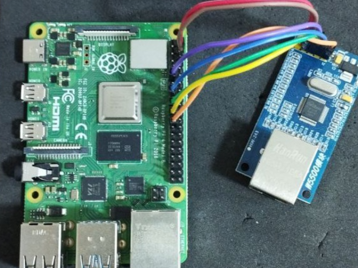
Their working setup was:
Bus: SPI1
Overlay: dtoverlay=spi1-1cs
Pins:
SCK → GPIO 21
MOSI → GPIO 20
MISO → GPIO 19
CS → GPIO 18 (chip-select that actually toggles under this overlay)
Once they aligned all of the above, spi_test and the W5500 driver started working immediately.
📘 WIZnet Insight
Here’s what engineers often miss when using W5500 on Raspberry Pi:
The Raspberry Pi 4 has multiple SPI bus options (SPI0, SPI1, SPI5 depending on firmware).
Not all CS pins are valid for all overlays.
For example, spi1-1cs gives only one valid CS, while spi1-3cs maps CS0/1/2 to different GPIOs.
If CS never toggles, the W5500 appears “dead”.
The chip will not drive MISO unless CS is pulled low.
For stable operation, we strongly recommend:
SPI clock ≤ 30 MHz (best compatibility)
Dedicated CS pin, avoid sharing with other SPI slaves
Confirm with logic analyzer if available (CS alignment is the #1 failure mode)