
RP2040 + W5100S Multicore Basic
RP2040 Multicore basic with W5100s
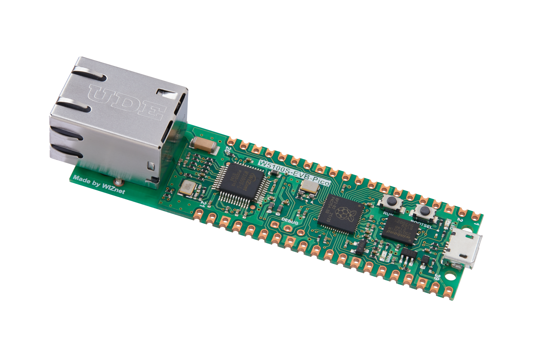
WIZnet - W5100S-EVB-Pico
x 1
Hello!
Today, I will explain a project where we use both cores of the RP2040 mounted on the W5100S-EVB-PICO to read ADC data and send this data to a connected TCP client!
The Raspberry Pi RP2040 used in the W5100S-EVB-PICO has two cores (M0+).
If you have used the W5100S-EVB-PICO, you will know that Wiznet provides basic sample codes.
The examples are all single-core implementations, and to better utilize the hardware resources of the RP2040, it's more efficient to implement using multi-cores.
However, many of the RP2040 multi-core examples available online are implemented in MicroPython.
While these examples make multi-core implementation easier, they don't align with the ultimate goal of this project: to efficiently use limited embedded hardware resources. Hence, we used the C language for this project.
The following sections will explain the necessary hardware connections and software settings for operating the project.
You can use the RPI-PICO and the W5100S module for hardware, but I used the W5100S-EVB-PICO EVB that includes both the RP2040 and W5100S.
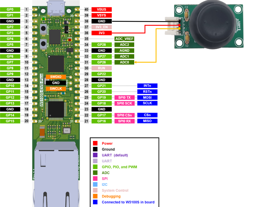
For ADC input, you can use a variable resistor, but I used an XY-Joystick for future projects. The XY-Joystick module I used can output ADC values for both the X and Y axes, but this project only takes one ADC input.
The ADC input is fed into GP26 (ADC0).
The W5100S is mounted on the W5100S-EVB-PICO and is set to SPI0 (MOSI - GP19, MISO - GP16, SCK - SP18, CS - GP17, INT - GP21, RST - GP20).
For multi-core implementation, I referred to the pico_multicore section from the PICO-SDK documentation provided by Rpi.
Below is the main code for the project.
Flow of the main function:
System clock initialization: Call the init_clock_khz function.
Initialize standard I/O: Call the stdio_init_all function.
Wiznet W5100S initialization: Initialize W5100S using wizchip functions.
Network setting: Configure the network using g_net_info.
ADC initialization: Initialize the ADC and ADC pins.
Run Core1: Start reading the ADC value in Core1 using the read_adc_core1 function.
Print network information: Display the current network configuration information.
Infinite loop: Periodically send ADC data to the TCP client using the send_adc_data_to_client function.
The complete source code is posted on a Github link, so please refer to it.
Here is a video of the project in operation.
For the TCP client, we used herculas.exe
In future projects, we will use this project as a basis to explore various multi-core projects.
Thank you for reading this long post.
안녕하세요!
오늘은 W5100S-EVB-PICO에 실장된 RP2040의 두개의 core를 활용하여 ADC 데이터를 읽고 해당 데이터를 연결된 TCP client에 전송하는 프로젝트에 대해 설명 드리겠습니다!
W5100S-EVB-PICO에 사용된 라즈베리파이 RP2040에는 2개의 Core(M0+)가 있습니다.
W5100S-EVB-PICO를 사용해보신 분들이라면 Wiznet에서 기본 예제들을 제공한다는 사실을 알고계실겁니다.
해당 예제들은 모두 싱글코어로 구현된 예제들이고, RP2040의 HW 리소스를 좀 더 활용하기 위해서는 멀티코어를 활용하여 구현하는게 효율적입니다.
하지만 많은 웹상의 많은 RP2040 멀티코어 예제들이 MicroPython으로 구현되어있습니다.
해당 예제들을 사용한다면 Multi-Core를 구현하기 수월하겠지만, 이 프로젝트의 궁극적인 목표인 한정된 임베디드 HW 리소스를 효율적으로 사용하는 목표에는 적합하지 않습니다. 그렇기 때문에 본 프로젝트에서는 C 언어를 사용하였습니다.
아래 글 부터는 프로젝트를 구동하는데 필요한 HW 연결과 SW 세팅을 설명 드리겠습니다.
HW는 RPI-PICO와 W5100S 모듈을 사용하셔도 되지만, 저는 RP2040과 W5100S가 포함된 EVB인 W5100S-EVB-PICO를 사용하였습니다.
ADC 입력은 가변저항을 사용해도 되지만, 추후에 다른 프로젝트에 사용하기 위해 XY-Joystick을 사용했습니다. 사용한 XY-Joystick 모듈은 X축과 Y축 ADC 값을 2개 출력 가능하지만 본 프로젝트에서는 1개의 ADC만 입력으로 받았습니다.
ADC 입력은 GP26번 (ADC0)로 입력됩니다.
W5100S는 W5100S-EVB-PICO에 실장되어있고 SPI0(MOSI - GP19, MISO - GP16, SCK - SP18, CS - GP17, INT - GP21, RST - GP20)으로 세팅하였습니다.
Multi-Core 구현을 위해 Rpi에서 제공하는 PICO-SDK 문서중 pico_multicore를 참고했습니다.
아래는 프로젝트의 Main에 해당하는 코드입니다.
간략하게 설명드리면 아래와 같습니다.
init_clock_khz: 시스템 클럭 설정 함수입니다. 클럭의 소스 및 주파수를 설정합니다.
read_adc_core1: Core1에서 동작할 함수입니다. ADC 값을 주기적으로 읽고, 읽은 값을 FIFO를 통해 Core0에 전송합니다.
send_adc_data_to_client: Core0에서 동작하는 함수로, Core1에서 읽은 ADC 값을 가져와서 TCP 클라이언트에 전송합니다. 소켓의 상태에 따라 연결 및 데이터 전송을 관리합니다.
메인 함수의 흐름:
시스템 클럭 초기화: init_clock_khz 함수 호출
표준 입출력 초기화: stdio_init_all 함수 호출
Wiznet W5100S 초기화: wizchip 관련 함수들로 W5100S 초기화
네트워크 설정: g_net_info를 사용하여 네트워크 설정
ADC 초기화: ADC 및 ADC 핀 초기화
Core1 실행: Core1에서 read_adc_core1 함수를 실행하여 ADC 값을 읽기 시작
네트워크 정보 출력: 현재 네트워크 설정 정보를 출력
무한 루프: send_adc_data_to_client 함수를 통해 ADC 데이터를 TCP 클라이언트에게 주기적으로 전송
전체 소스코드는 Github link에 올려두었으니 참고 바랍니다.
해당 프로젝트의 구동 영상입니다.
TCP client는 herculas.exe 를 사용하였습니다.
이후에 진행하는 프로젝트에는 본 프로젝트를 활용하여 다양한 멀티코어 프로젝트를 진행해 보겠습니다.
긴 글 읽어주셔서 감사합니다.
-
Multicore_example
RP2040 Multicore_example with W5100S
