


Inverter + W5500
TI DSP28377D + W5500 HW

WIZnet - W5500
x 1

How to Add WIZnet W5500 Ethernet Communication to a DSP28377D-Based High-Power Inverter?
Summary
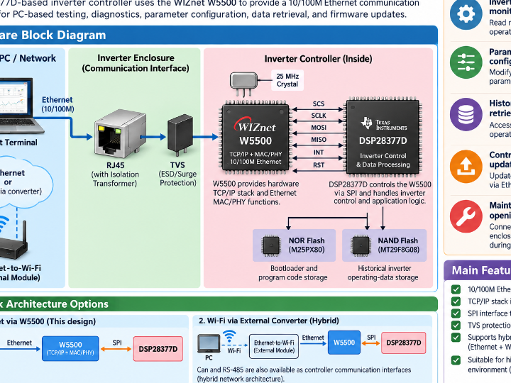
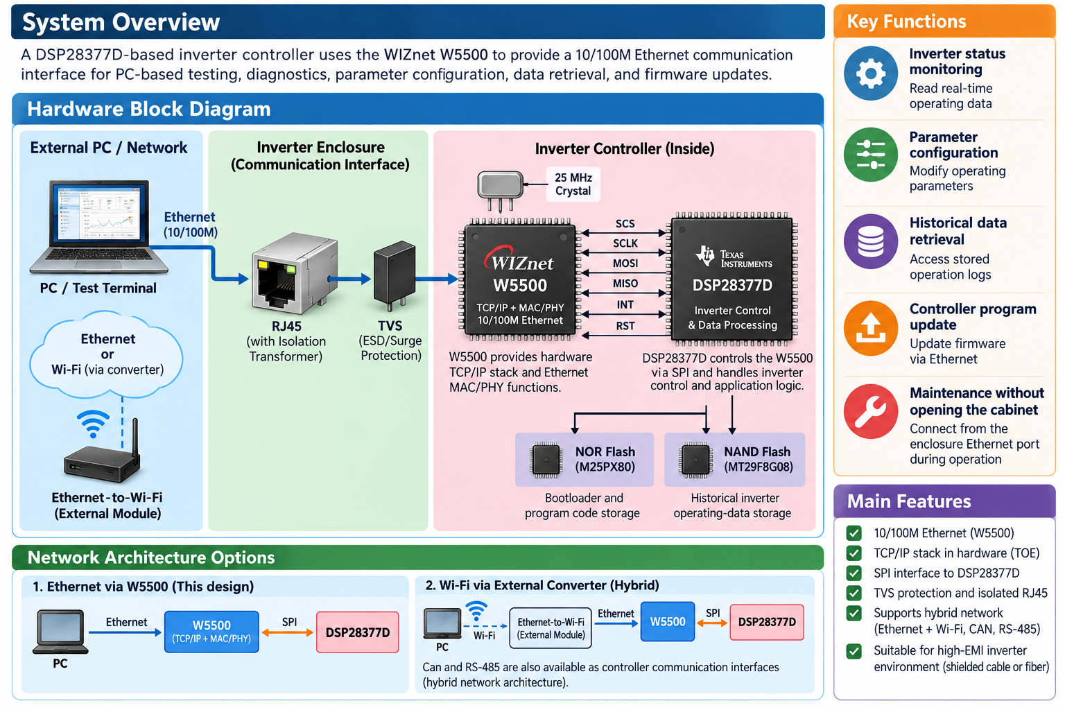
This design adds a WIZnet W5500 to a DSP28377D-based high-power inverter controller to provide a 10/100M Ethernet path for PC-based testing and diagnostics. The W5500 connects to the DSP through SPI and supplies the TCP/IP stack and Ethernet MAC/PHY functions that are not integrated into the DSP28377D. Its Ethernet signals pass through TVS protection and an RJ45 interface with isolation before reaching the inverter enclosure over shielded twisted-pair cabling. The resulting interface allows inverter status transfer, parameter modification, historical-data retrieval, and controller program updates without opening the cabinet during operation. CN209765313U
What the Project Does
Chinese utility model patent CN209765313U describes a communication device for testing and diagnosing a high-power inverter. The architecture integrates a DSP processing module, an Ethernet communication module, and storage modules into the inverter controller, while routing the Ethernet interface to the inverter enclosure. The patent was filed on June 13, 2019 and published on December 10, 2019. CN209765313U
In the detailed implementation, the controller uses a DSP28377D, a W5500-based Ethernet circuit, an M25PX80-series NOR Flash, and an MT29F8G08-series NAND Flash. The NOR Flash is described as storage for the Bootloader and program code, while the NAND Flash stores historical inverter operating-state data for later retrieval and fault analysis. CN209765313U
The main communication path is:
PC / Test Terminal
        │
        │ Ethernet
        ▼
Inverter Enclosure Ethernet Interface
        │
        │ Shielded Twisted Pair
        ▼
RJ45 + Isolation Transformer
        │
       TVS
        │
        ▼
  WIZnet W5500
        │
        │ SPI
        ▼
    DSP28377D
        │
        ├── NOR Flash
        └── NAND Flash
Through this path, the PC can communicate with the inverter for operating-state data transfer, operating-parameter modification, historical-data retrieval, and controller program updates. Routing the Ethernet connection to the enclosure also allows a test terminal to communicate with the controller without opening the inverter cabinet during operation. CN209765313U
The patent also provides clear evidence of a hybrid communication architecture. CAN and RS-485 are retained as controller communication interfaces, while an external Ethernet-to-Wi-Fi module can be attached to the enclosure Ethernet port for wireless communication with the PC. Figure 4 on page 14 specifically illustrates the path from the DSP28377D through Ethernet and an external Ethernet-to-Wi-Fi module to the test computer. CN209765313U
Where WIZnet Fits
The WIZnet component in this design is the W5500 hardwired TCP/IP Ethernet controller.
The patent gives a specific technical reason for its placement. The DSP28377D does not integrate an Ethernet MAC controller, so the W5500 provides the missing network functions. The patent describes the W5500 as integrating a TCP/IP protocol stack together with 10/100M Ethernet MAC and PHY functions. The DSP28377D communicates with it through SPI, reading and writing W5500 registers to configure network information such as the IP address and select W5500 functions. CN209765313U
The functional split is therefore:
| Component | Interface | Role in This Design |
|---|---|---|
| DSP28377D | SPI | Inverter control, data processing, and W5500 register control |
| WIZnet W5500 | SPI ↔ Ethernet | TCP/IP stack, Ethernet MAC/PHY, and network communication |
| TVS protection | Ethernet signal lines | Protection on the external Ethernet path |
| RJ45 | 10/100M Ethernet | Physical connection to the PC or external network |
| NOR Flash | DSP-side storage | Bootloader and program-code storage |
| NAND Flash | DSP-side storage | Historical inverter operating-data storage |
The design also provides direct evidence for classifying the W5500 as a TCP/IP offload device in this system. The patent states that the W5500 contains the TCP/IP stack and that using it avoids implementing the TCP/IP protocol directly in DSP software. The DSP instead controls the network device through SPI register access. CN209765313U
The patent presents two alternative Ethernet architectures for comparison. One adds an ARM processor with an Ethernet MAC, a separate PHY, and dual-port RAM between the ARM and DSP. Another uses an Ethernet MCU with integrated MAC and PHY but still requires dual-port RAM for communication with the DSP. In the W5500 implementation, the DSP28377D communicates directly with the W5500 over SPI. CN209765313U
Implementation Notes
The source is a patent rather than a firmware repository, so verified DSP28377D source code and W5500 initialization functions are not available. For that reason, no fabricated firmware example is presented here. The implementation details below are limited to the hardware connections and behavior explicitly documented in the patent.
Figure 5 on page 14 shows the actual interface between the DSP28377D and W5500: CN209765313U
DSP28377D                    W5500
────────────────────────────────────
SCS        ────────────────> SCS
SCLK       ────────────────> SCLK
MOSI       ────────────────> MOSI
MISO       <──────────────── MISO
INT        <──────────────── INT
RST        ────────────────> RST

                              │
                         TX± / RX±
                              │
                              ▼
                         TVS Protection
                              │
                              ▼
                    RJ45 with Isolation
The same diagram also shows a crystal circuit and operating-mode selection connections around the W5500. This is therefore more than a conceptual four-wire SPI connection: the disclosed implementation includes interrupt and reset handling as well as the Ethernet-side protection and RJ45 interface. CN209765313U
The firmware behavior is partially described in the patent. The DSP28377D program accesses W5500 registers over SPI, configures basic Ethernet information including the IP address, and selects W5500 functions. However, the source does not specify the SPI clock frequency, actual DSP GPIO assignments, MAC or IP values, TCP versus UDP selection, port numbers, socket-buffer allocation, or application-layer protocol. Those implementation details therefore cannot be verified from this source. CN209765313U
Practical Tips / Pitfalls
- Account for inverter EMI when routing Ethernet. The patent specifically discusses strong electromagnetic interference inside the inverter and proposes shielded twisted-pair cable or optical fiber for the communication path. CN209765313U
- Route the Ethernet interface to an accessible enclosure panel. This allows a PC to connect to the internal controller during operation without opening the inverter cabinet. CN209765313U
- Design for INT and RST as well as the four basic SPI signals. Figure 5 shows SCS, SCLK, MOSI, MISO, INT, and RST between the DSP28377D and W5500. CN209765313U
- Include Ethernet-side protection in the hardware review. The disclosed W5500 implementation places TVS protection between the W5500 Ethernet signals and the RJ45 path. CN209765313U
- Keep Wi-Fi outside the high-EMI enclosure when following this architecture. The patent proposes connecting an external Ethernet-to-Wi-Fi converter at the enclosure Ethernet interface rather than integrating the wireless path inside the inverter. CN209765313U
- Do not infer performance figures that the source does not provide. The patent specifies 10/100M Ethernet but does not provide measured throughput, latency, CPU utilization, or comparative benchmark results. CN209765313U
FAQ
Q: Why is the W5500 used with the DSP28377D in this inverter?
A: According to the patent, the DSP28377D does not contain an Ethernet MAC controller. The W5500 supplies the TCP/IP stack and Ethernet MAC/PHY functions, while the DSP controls it through SPI. This avoids implementing the TCP/IP protocol directly in DSP software in the disclosed architecture. CN209765313U
Q: How does the W5500 connect to the DSP28377D?
A: It connects through SPI. Figure 5 on page 14 shows SCS, SCLK, MOSI, and MISO along with INT and RST. On the network side, the W5500 TX± and RX± signals are routed through TVS protection toward an RJ45 interface with isolation. CN209765313U
Q: What role does the W5500 play in this specific inverter system?
A: The W5500 provides the Ethernet communication path between the DSP28377D controller and an external PC. The patent describes using this path for inverter status-data transfer, operating-parameter modification, historical-data retrieval, and controller program updates. CN209765313U
Q: Can a beginner implement this design?
A: The architecture requires more than basic SPI knowledge. An implementation must account for DSP28377D firmware, W5500 register control, Ethernet signal routing, RJ45 isolation and protection, and the high-EMI environment of a power inverter. The patent also does not provide complete firmware source code, so practical DSP and Ethernet hardware-development experience would be required to reproduce the system. CN209765313U
Q: How does the W5500 approach differ from the ARM + PHY alternative described in the patent?
A: In the alternative architecture, an ARM processor provides the Ethernet MAC, a separate PHY connects it to Ethernet, and dual-port RAM transfers data between the ARM and DSP. In the W5500 architecture, the DSP28377D communicates directly with the W5500 through SPI, while the W5500 provides the TCP/IP stack and MAC/PHY functions. The patent does not provide benchmark data establishing a performance or cost advantage for either architecture. CN209765313U
Source
Original Source: Chinese Utility Model Patent CN209765313U, A Communication Device for an Inverter (一种变频器的通信装置) CN209765313U
Patent Holder: Zhuhai Gree Electric Appliances Co., Ltd. (珠海格力电器股份有限公司)
Inventors: Zhou Weibang, Zhang Lianghao, Li Yili, Jin Keke
Application No.: 201920887226.6
Filing Date: June 13, 2019
Publication No.: CN 209765313 U
Publication Date: December 10, 2019
Document Type: Chinese Utility Model Patent
License: No software license is identified in the patent document. CN209765313U
Tags
#W5500 #WIZnet #DSP28377D #Ethernet #TOE #HybridNetwork #SPI #RJ45 #Inverter #PowerElectronics #IndustrialEthernet #IndustrialControl