
ESP32 + W5500 Seamless Wi-Fi & Ethernet Auto-Switching
ESP32 + W5500 Seamless Wi-Fi & Ethernet Auto-Switching
How to Implement Ethernet–Wi-Fi Auto Switching with W5500 on ESP32?
Summary
This project demonstrates how to implement automatic network failover between Ethernet and Wi-Fi on an ESP32 using the WIZnet W5500 Ethernet controller. The W5500 provides wired TCP/IP connectivity, while the ESP32’s internal Wi-Fi handles wireless fallback. The firmware continuously monitors link status and dynamically switches the active interface, ensuring uninterrupted internet connectivity in an educational embedded networking setup.
What the Project Does
This project builds a dual-network ESP32 system capable of:
Connecting to the internet via W5500 Ethernet (SPI interface)
Falling back to Wi-Fi when Ethernet is disconnected
Hosting a captive portal to configure Wi-Fi credentials
Providing visual feedback through an LED indicator
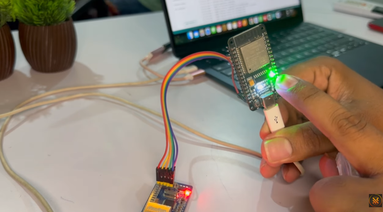
System Components
ESP32 (or ESP8266) – Main MCU
W5500 Ethernet module – Wired TCP/IP interface
Ethernet cable (RJ45)
Boot button – Used to reset Wi-Fi credentials
Status LED (GPIO 2) – Indicates connection state
Data Flow Logic
On boot, the system attempts Ethernet first.
If Ethernet link is detected → network stack uses Ethernet.
If Ethernet link fails → system switches to Wi-Fi.
If Wi-Fi credentials are missing → captive portal opens.
Boot button (held 5 seconds) → clears saved Wi-Fi credentials.
The system therefore implements priority-based network selection with automatic recovery.
Where WIZnet Fits
This project uses the WIZnet W5500 Ethernet controller.
Role in the Architecture
Provides hardware TCP/IP stack over SPI
Handles MAC + PHY layer internally
Offloads socket management from ESP32
Detects Ethernet link status via PHY registers
The W5500 connects to ESP32 using:
MOSI
MISO
SCK
CS (Chip Select → GPIO 5 in this project)
Because W5500 contains an internal 32 KB buffer and supports up to 8 hardware sockets, it allows the ESP32 firmware to focus on:
Link monitoring
Failover decision logic
Wi-Fi management
Captive portal configuration
In this project, W5500 acts as the primary transport layer, while Wi-Fi acts as the secondary transport.
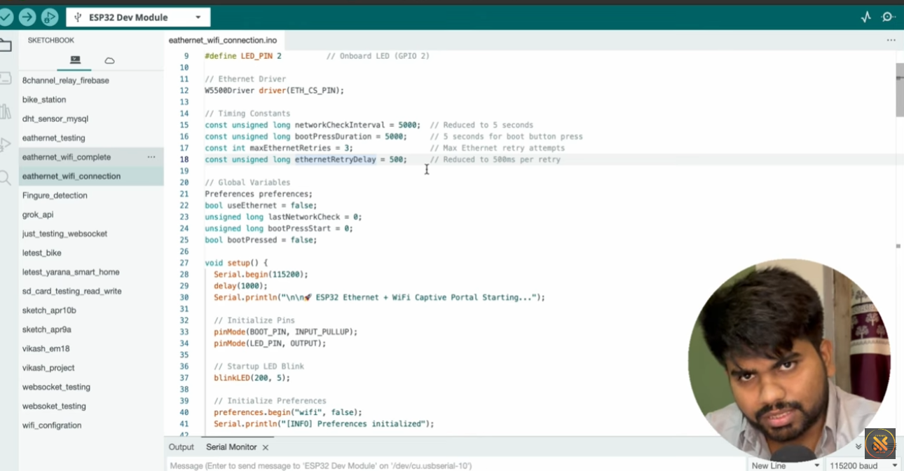
Implementation Notes
The original video description explains the logic but does not provide direct repository access. Therefore, the following structure is based on the demonstrated firmware architecture.
Conceptual integration example based on WIZnet ioLibrary
#include "wizchip_conf.h"
#include <SPI.h>

// SPI chip select pin
#define W5500_CS 5

void setupEthernet() {
    SPI.begin();
    pinMode(W5500_CS, OUTPUT);

    uint8_t txSize[8] = {2,2,2,2,2,2,2,2};
    uint8_t rxSize[8] = {2,2,2,2,2,2,2,2};

    wizchip_init(txSize, rxSize);

    wiz_NetInfo netinfo = {
        .mac = {0x00,0x08,0xDC,0x01,0x02,0x03},
        .dhcp = NETINFO_DHCP
    };

    wizchip_setnetinfo(&netinfo);
}
Failover Logic (Conceptual Flow)
if (ethernetLinkUp()) {
useEthernet();
WiFi.disconnect(true);
}
else {
connectWiFi();
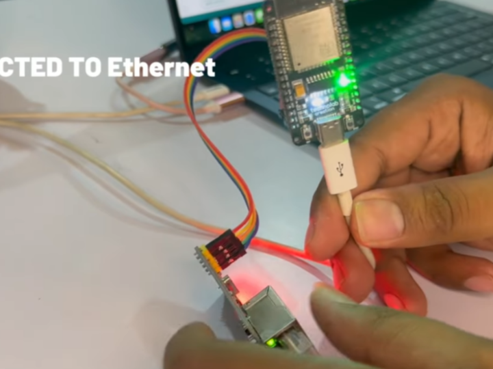
}Observed Behavior from Demonstration
Ethernet cable plugged → LED ON (Ethernet active)
Ethernet unplugged → LED blinking (Wi-Fi connecting)
Wi-Fi connected → LED stable
Boot button held 5 seconds → Wi-Fi credentials erased
The firmware repeatedly checks Ethernet link state at short intervals (~500 ms window with periodic polling), enabling near-real-time switching.
Practical Tips / Pitfalls
Use stable SPI wiring; long jumper wires can cause link instability.
Ensure CS pin is correctly defined (GPIO 5 in the demonstration).
Always verify PHY link status before declaring Ethernet “connected”.
Disable Wi-Fi when Ethernet is active to avoid dual-stack conflicts.
Store Wi-Fi credentials in non-volatile memory (Preferences library).
Use LED states clearly (OFF = no network, BLINK = connecting, ON = connected).
Add watchdog reset if network switching logic blocks execution.
FAQ
Q: Why use the W5500 in this project?
A: The W5500 provides a complete hardware TCP/IP stack over SPI, allowing the ESP32 to handle network switching logic while Ethernet communication is managed internally by the controller.
Q: How is the W5500 connected to ESP32?
A: It connects via SPI using MOSI, MISO, SCK, and a CS pin (GPIO 5 in this project). Power and ground are also required. No external TCP/IP stack is needed.
Q: What role does the W5500 play in this specific design?
A: It acts as the primary wired network interface. The firmware prioritizes Ethernet, monitors its link status, and falls back to Wi-Fi only when Ethernet is disconnected.
Q: Can beginners follow this project?
A: Yes, if they understand basic SPI wiring and Wi-Fi configuration on ESP32. Knowledge of network concepts such as DHCP and link status is helpful.
Q: What happens if both Ethernet and Wi-Fi are available?
A: In this design, Ethernet has priority. When link is detected, Wi-Fi is disabled to ensure a single active transport layer.
Source
Original Video Demonstration:
https://www.youtube.com/watch?v=pT2NTDTOlFQ
License: Not specified by the author.
Tags
#W5500
#ESP32
#EthernetFailover
#NetworkStack
#SPI
#EmbeddedNetworking
#EducationalProject