
ESP32 + W5500 Lite + Tasmota = New Project v1.0
ESP32 + W5500 Lite + Tasmota
프로젝트 개요
이 UCC는 LetsMakeRobot 블로그에 기록된 Ethernet Tasmota의 장기적인 진화를 정리한다. Wi-Fi 기반 ESP 장치에서 시작해 RMII 이더넷 설계를 거쳐, GPIO 사용량을 줄이고 확장성을 높이기 위해 ESP32 + W5500 Lite 기반 SPI 이더넷 구조로 전환된 과정을 다룬다.
LetsMakeRobot Ethernet Tasmota 프로젝트 개요
LetsMakeRobot는 ESP8266/ESP32, Tasmota, DIY 스마트홈 하드웨어를 중심으로 다년간의 제작 기록을 축적해온 메이커 블로그다.
이 블로그의 특징은 단일 완성형 튜토리얼이 아니라, 여러 해에 걸쳐 동일한 주제를 반복적으로 개선한다는 점이다.
Ethernet Tasmota 시리즈는 2021년부터 2025년까지 이어진 연속 프로젝트로, 네트워크 방식과 하드웨어 구조가 어떻게 변화했는지를 시간순으로 보여준다.
이는 “정답 설계”가 아니라, 설계 선택과 그 결과를 기록한 사례로서 의미를 가진다.
Ethernet Tasmota의 구조적 진화
2021-06-29: ESP + Tasmota의 Wi-Fi 기반 구성
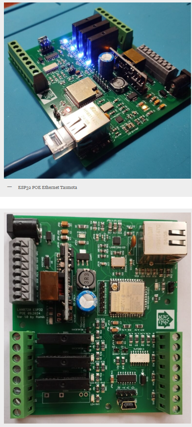
2023-12-07: LAN8720A RMII Ethernet PHY 도입

2024-09-27: LAN8720A 기반 커스텀 이더넷 보드
2025-10-10: ESP32 + W5500 Lite + Tasmota 신규 프로젝트 선언
이 흐름은 단순한 업그레이드가 아니라, 하드웨어 구조 자체를 재검토한 과정으로 볼 수 있다.

LAN8720A에서 W5500으로의 전환 의미
ESP32 환경에서 W5500은 하드웨어 TCP/IP 스택을 활용하기 위한 선택이 아니다.
MACRAW 모드 사용 시, 네트워크 스택은 여전히 ESP32의 LwIP가 처리한다.
그럼에도 W5500이 선택된 이유는 명확하다.
RMII PHY는 많은 GPIO를 소모한다
SPI Ethernet은 GPIO 점유를 최소화한다
GPIO 여유는 곧 기능 확장 가능성이다
Tasmota 기반 장치에서 릴레이, 센서, 버튼, 확장 인터페이스는 모두 GPIO에 의존한다.
이 관점에서 W5500은 “이더넷 칩”이 아니라 시스템 구조를 유연하게 만드는 도구로 작동한다.
FAQ (요약)
왜 LAN8720A 대신 W5500인가? → GPIO 절감과 확장성
TCP 스택 오프로딩이 핵심인가? → 아니다, 구조가 핵심이다
SPI Ethernet의 장점은? → 핀 수 감소, PCB 단순화
누가 쓰기 적합한가? → 중급 이상 메이커
확장 가능성은? → GPIO 여유를 기반으로 충분히 가능
마무리
이 Ethernet Tasmota 프로젝트는 “더 빠른 이더넷”이 아니라
“더 설계하기 쉬운 이더넷”을 선택한 사례다.
그 선택의 중심에 WIZnet W5500이 있다.
Original Sources
LetsMakeRobot Ethernet Tasmota Series
https://letsmakerobot.ru/category/umnyj-dom/ethernet-tasmota/
https://letsmakerobot.ru/category/umnyj-dom/ethernet-tasmota/page/2/
How Did Ethernet Tasmota Evolve from Wi-Fi to SPI Ethernet with W5500?
Project Overview
This project documents the long-term evolution of Ethernet Tasmota on the LetsMakeRobot blog. Starting from Wi-Fi-based ESP devices, it progresses through RMII Ethernet designs and culminates in a new ESP32 + W5500 Lite architecture, chosen primarily to reduce GPIO usage and improve hardware expandability.
Background: What Is the LetsMakeRobot Ethernet Tasmota Series?
LetsMakeRobot is a maker-oriented blog that focuses on DIY smart home systems, ESP8266/ESP32 firmware, Tasmota customization, and custom hardware design.
Rather than publishing one-off tutorials, the blog documents multi-year iterative projects, where earlier design decisions are revisited, revised, and sometimes replaced based on real implementation experience.
Within this context, the Ethernet Tasmota series stands out as a continuous project spanning from 2021 to 2025, covering multiple hardware architectures and design directions.
Across several posts, the blog records how Tasmota-based smart home nodes evolved from wireless-only devices into Ethernet-based systems, and eventually into SPI Ethernet designs using WIZnet hardware.
This accumulated timeline makes the project valuable not as a “how-to,” but as a record of architectural trade-offs encountered when building reliable and expandable Tasmota devices.
Timeline of the Ethernet Tasmota Project
2021-06-29 — Wi-Fi-Based Tasmota

The earliest post in the series uses ESP-based hardware running Tasmota exclusively over Wi-Fi.
This stage establishes baseline functionality and confirms Tasmota’s suitability for smart home automation, but remains limited to wireless connectivity.
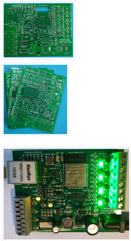
2023-12-07 — Transition to Ethernet with LAN8720A

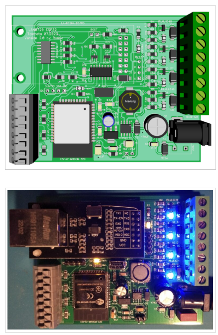
A later post introduces Ethernet by adopting the LAN8720A RMII Ethernet PHY with ESP32.
This marks the first move away from Wi-Fi and demonstrates a conventional ESP32 + PHY architecture using RMII signals.
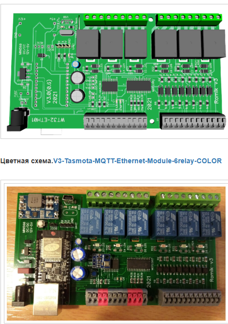
2024-09-27 — Custom Ethernet Board


Building on the LAN8720A design, a custom Ethernet board is introduced.
This phase shows increasing confidence in hardware design and long-term operation, but remains fundamentally tied to RMII-based Ethernet connectivity.
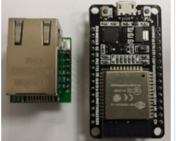
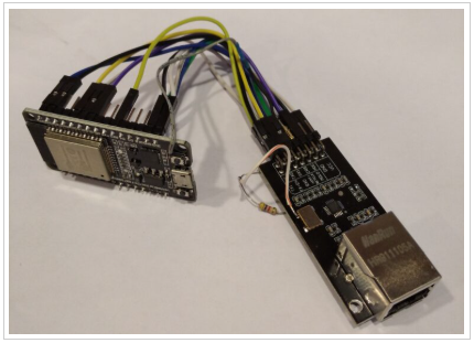
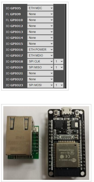
2025-10-10 — ESP32 + W5500 Lite + Tasmota (New Project v1.0)

The most recent post announces a new project direction:
ESP32 + W5500 Lite IO module + Tasmota.
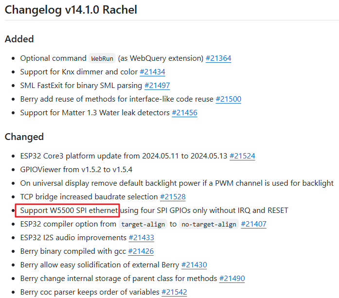
Despite already having a working LAN8720A-based board, the project restarts with a SPI Ethernet controller, signaling a deliberate architectural shift rather than an incremental upgrade.
Why Move from LAN8720A to W5500? (Architectural Perspective)
In this project, the decision to adopt WIZnet W5500 is not about Ethernet performance or TCP/IP acceleration.
On ESP32, W5500 is used in MACRAW mode, with the LwIP stack still running on the ESP32.
Instead, the motivation lies in hardware structure and I/O efficiency.
LAN8720A (RMII PHY) Characteristics
Requires RMII interface between ESP32 and PHY
Consumes 8–10 GPIO pins (TXD, RXD, CRS, MDC, MDIO, REF_CLK, etc.)
Increases pin multiplexing constraints on ESP32
Complicates routing and limits available IO for peripherals
W5500 (SPI Ethernet Controller) Characteristics
Uses SPI interface
Requires only 4–5 GPIO pins (MOSI, MISO, SCK, CS, optional INT)
Frees ESP32 pins for relays, sensors, displays, or serial buses
Simplifies PCB routing and board-level expansion
In other words:
LAN8720A enables Ethernet.
W5500 enables Ethernet plus expansion.
For a Tasmota-based smart home node—where GPIO availability directly translates into functional capability—this distinction becomes critical.
Role of WIZnet W5500 in This Project
In the latest project iteration, W5500 serves as:
A SPI-based Ethernet interface for ESP32
A method to reduce GPIO consumption
A foundation for more flexible and scalable hardware designs
By decoupling Ethernet connectivity from the RMII pin-heavy approach, the project gains freedom to grow beyond a simple networked switch and toward a modular smart home node.
FAQ
Q1: Why choose W5500 instead of LAN8720A for ESP32?
A: The key reason is GPIO efficiency. LAN8720A requires many RMII pins, while W5500 uses SPI and needs far fewer GPIOs. This leaves more pins available for relays, sensors, and other peripherals in a Tasmota-based device.
Q2: Does W5500 offload the TCP/IP stack in this project?
A: No. In ESP32 + Tasmota environments, W5500 is typically used in MACRAW mode, and the TCP/IP stack is still handled by ESP32’s LwIP. The benefit here is architectural simplicity, not protocol offloading.
Q3: What problem does SPI Ethernet solve in smart home hardware?
A: SPI Ethernet minimizes pin usage and simplifies PCB routing. This makes it easier to design compact boards that still support multiple IO features such as relays, buttons, sensors, and serial interfaces.
Q4: Is this approach suitable for beginners?
A: It is best suited for intermediate makers familiar with ESP32 pin multiplexing and basic PCB design. However, using a W5500 IO module can significantly lower hardware complexity compared to RMII-based Ethernet designs.
Q5: Can this design be extended further?
A: Yes. By preserving GPIO resources, the ESP32 + W5500 structure is well-suited for future extensions such as additional IO expanders, industrial interfaces, or alternative MCU platforms.
Original Sources
LetsMakeRobot Ethernet Tasmota Series
https://letsmakerobot.ru/category/umnyj-dom/ethernet-tasmota/
https://letsmakerobot.ru/category/umnyj-dom/ethernet-tasmota/page/2/