
W5100S, W5500 Auto-Negotiation analysis
Auto-Negotiation analysis
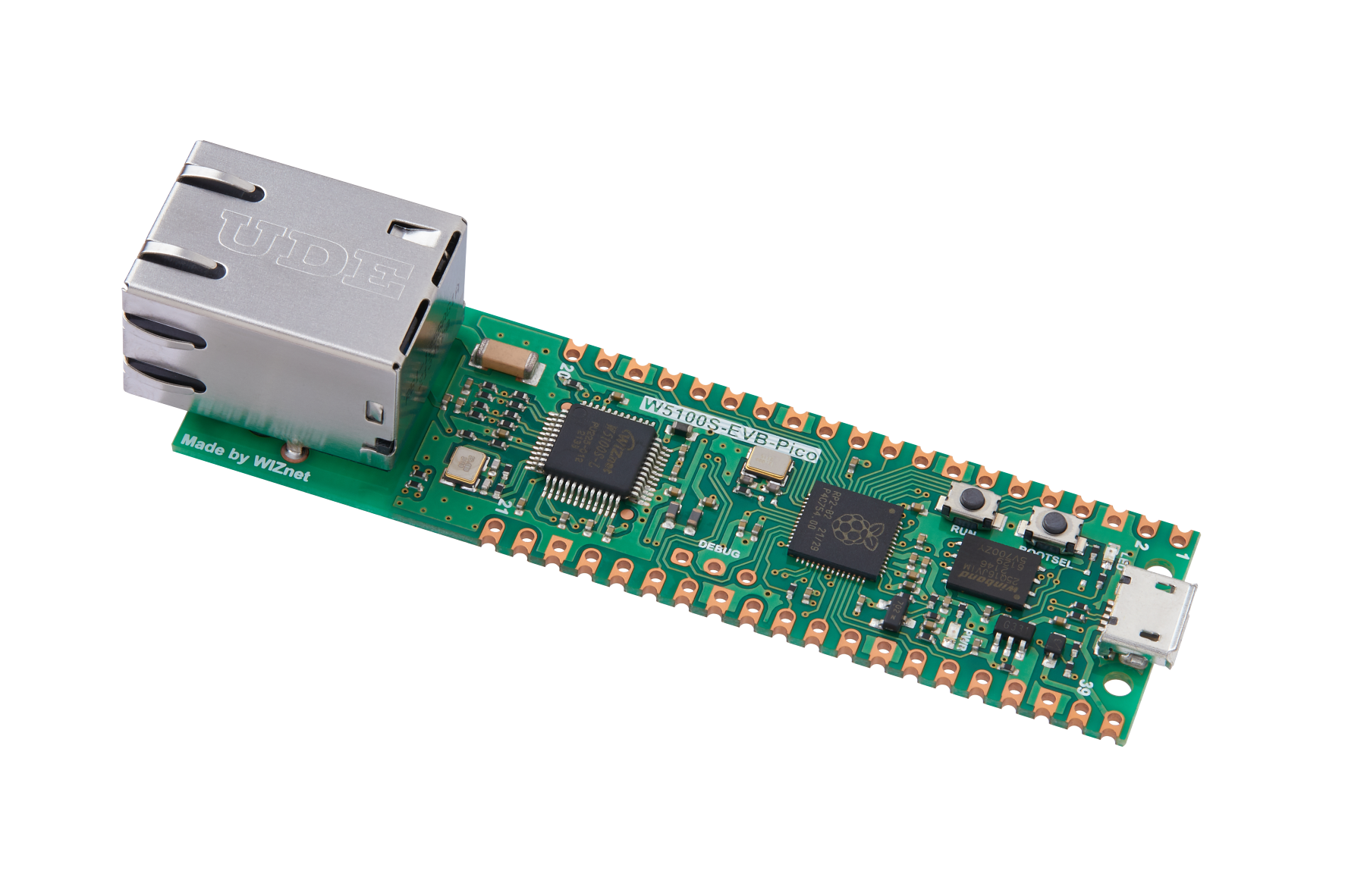
WIZnet - W5100S-EVB-Pico
x 1
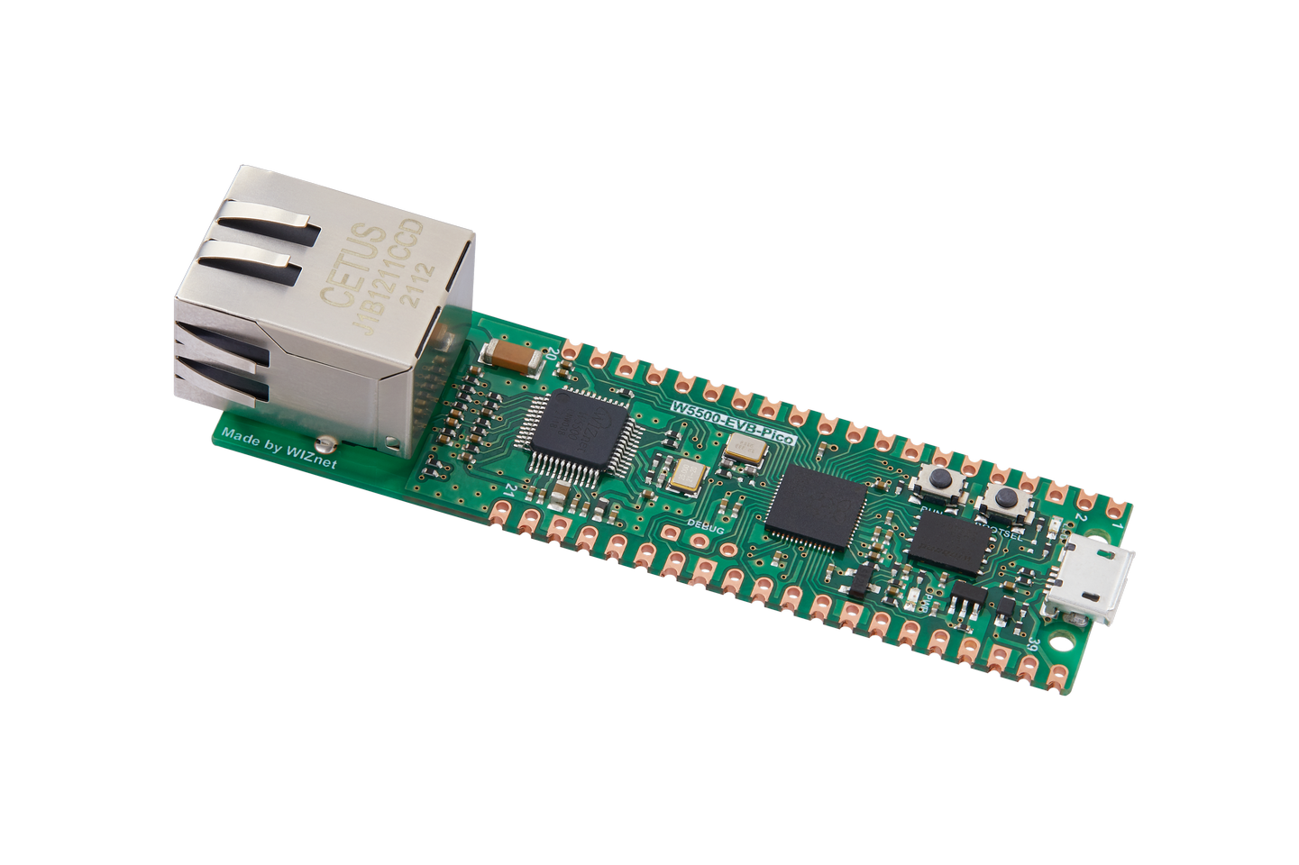
WIZnet - W5500-EVB-Pico
x 1
hello!
Today we're going to oscilloscope and analyze how the W5100S and W5500 auto-negotiate with other devices.
I recommend that you read and watch our article on Auto-Negotiation.
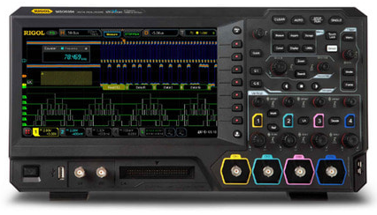
I used the MSO5354 oscilloscope from RIGOL,
Linkpartner used iptime's V504 switch.
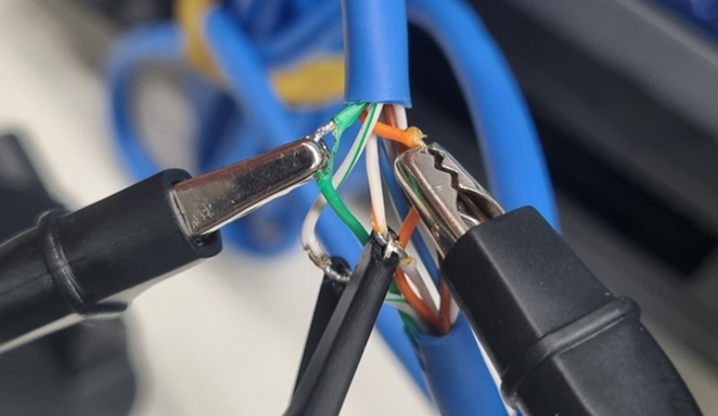
Measurements were made by stripping the middle sheath of the UTP cable, connecting the GND of the oscilloscope probe to RX- (or TX-) and the measurement part to RX+ (or TX+).
When measuring FLP waveforms only, only the UTP cable was connected and not the linkpartner.
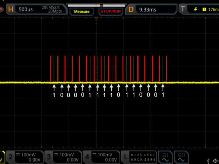
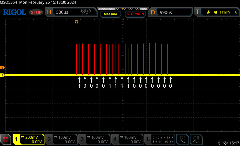
First, when you take an FLP waveform of link partner, iptime V504, you will see that
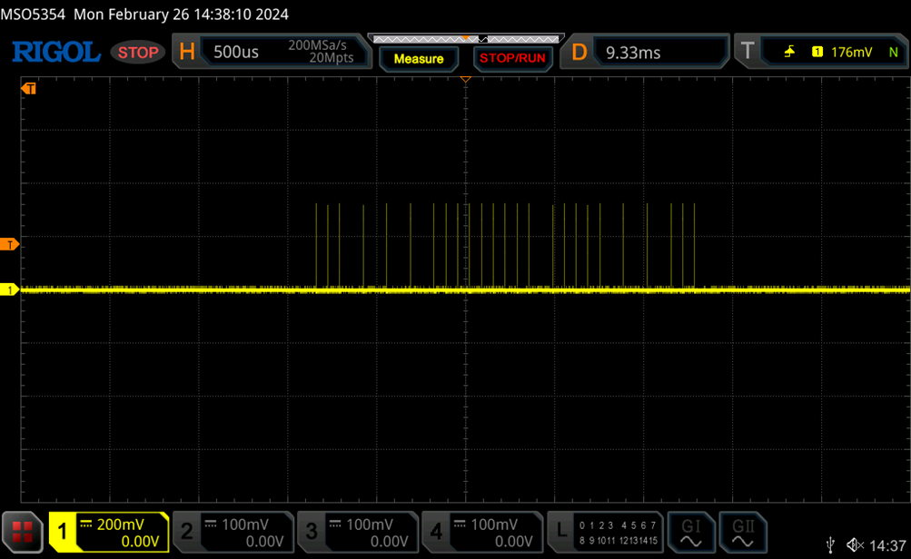
The FLP waveform consists of the CLK portion, shown in red, and the data between CLK.
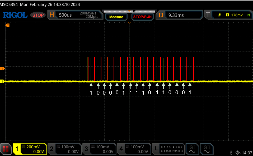
Reading the data between CLKs yields the data 1000011110110001.
This is shown below
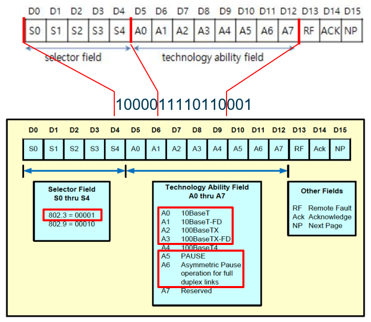
A5 and A6 of the Technology Ability Field bits are related to flow control and are described in detail below.
In the Technology Ability Field of the Fast Link Pulses (FLP) signal, the A5 and A6 bits indicate specific capabilities of the network equipment during the auto-negotiation process. They are used specifically to indicate flow control-related functions. The A5 and A6 bits are part of the IEEE 802.3 standard and play an important role in regulating data flow on Ethernet networks.
A5 Bit: PAUSE
The A5 bit indicates the general PAUSE function. PAUSE frames are part of the flow control mechanism defined in the IEEE 802.3x standard, which is used to manage network congestion on Ethernet networks. Equipment that supports PAUSE frames can receive a signal from other equipment on the network to suspend data transmission for a specific period of time and suspend data transmission accordingly. This feature helps prevent packet loss by regulating the flow of data between network equipment, especially in full duplex mode.
A6 Bit: Asymmetric PAUSE
The A6 bit indicates the Asymmetric PAUSE feature. This is a form of flow control using PAUSE frames that enables unidirectional flow control, meaning that PAUSE frames can be sent in one direction, but no PAUSE frames can be sent or received in the opposite direction. This is primarily useful on full-duplex links, where if congestion occurs in only one part of the network, you can temporarily control the flow of data in that direction while leaving communication in the other direction unaffected.
Importance of the PAUSE feature
Manage network congestion: PAUSE and Asymmetric PAUSE features are important for managing congestion on the network and preventing packet loss due to buffer overflows.
Efficient network operations: These features enable network equipment to manage data flows more efficiently and optimize the use of network resources.
In the Technology Ability Field of the FLP, the A5 and A6 bits are important indicators of whether the network equipment supports these advanced flow control capabilities. By exchanging this information through an automatic negotiation process, connected devices can recognize each other's capabilities and determine the optimal network connection settings.
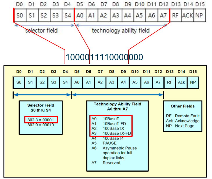
In the same way, if you connect a UTP cable without a LinkPartner for FLP waveform measurements on the W5500, you will see the following waveform on the TX, you can see the waveform as shown below.
I used W5500-EVB-PICO and no FW.
The 1000011110000000 bit is also interpreted as follows
When I connect the W5500 and iptime V504 and measure the moment they become a link, it looks like this
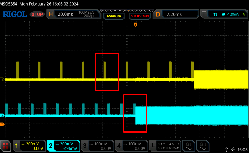
The waveform that follows the FLP is the IDLE_SIGNAL, which is a signal that is required to complete auto-negotiation properly and maintain the link state when no packets are being sent or received.
Izoom in and analyze the waveform of the section in red, it looks like this
you can see that the Ack bit is displayed as 1, which is different than when connecting without a link partner.
This means that the Ack is enabled because the FLP was received from the link partner.
This time, I will measure the W5100S-EVB-PICO.
Because the W5100S supports MDIX, the FLP waveforms alternate between TX and RX, unlike the W5500, which only generates FLP waveforms on TX.
However, when measuring with an oscilloscope, if I connected the TX and RX probes at the same time, the W5100S internal PHY confused the UTP cable connection and sometimes Link-UP worked even though the link partner was not connected.
The FLPs coming from TX and RX are the same waveform and mean the same thing as above.
W5100S-EVB-PICO와 iptime V504의 link시 파형은 W5500과 동일하나 Auto MDIX기능으로 인해 TX와 RX가 바뀌기도 하였습니다.
In this article, I took direct waveform measurements of how the W5100S and W5500 perform auto-negotiation.
Next time, I'll write a post that measures and analyzes a 100base-t signal encoded in the MLT-3 method.
안녕하세요!
오늘은 W5100S와 W5500이 어떻게 다른 장비와 Auto-Negotiation을 진행하는지 오실로스코프로 측정하고 분석해보겠습니다.
Auto-Negotiation 관련 글을 읽고 보시는 것을 추천드립니다.
장비는 RIGOL사의 MSO5354 오실로스코프를 사용했고,
링크파트너는 iptime의 V504 스위치를 사용했습니다.
측정은 UTP 케이블의 중간의 피복을 벗겨내고 오실로스코프 프로브의 GND를 RX-(또는 TX-)에 연결하고 측정부를 RX+(또는 TX+)에 연결하였습니다.
FLP 파형만 측정할 때는 UTP 케이블만 연결하고 링크파트너는 연결하지 않았습니다.
먼저 링크파트너인 iptime V504의 FLP 파형을 찍어보면
위와 같은 파형을 볼 수 있습니다.
FLP 파형은 빨간색으로 표시한 CLK 부분과 CLK사이의 데이터로 이루어져 있습니다.
CLK 사이의 데이터를 읽으면 1000011110110001 이라는 데이터가 나옵니다.
이는 아래와 같습니다.
Technology Ability Field 비트중 A5와 A6는 흐름제어와 관련된 기능으로써 자세한 기능은 아래와 같습니다.
FLP (Fast Link Pulses) 신호의 Technology Ability Field에서 A5와 A6 비트는 자동 협상 프로세스 중에 네트워크 장비의 특정 기능을 나타냅니다. 이들은 특히 흐름 제어 관련 기능을 지시하는 데 사용됩니다. A5와 A6 비트는 IEEE 802.3 표준의 일부로, 이더넷 네트워크에서 데이터 흐름을 조절하는 데 중요한 역할을 합니다.
A5 비트: PAUSE
A5 비트는 일반적인 PAUSE 기능을 나타냅니다. PAUSE 프레임은 IEEE 802.3x 표준에서 정의된 흐름 제어 메커니즘의 일부로, 이더넷 네트워크에서 네트워크 혼잡을 관리하는 데 사용됩니다. PAUSE 프레임을 지원하는 장비는 네트워크의 다른 장비로부터 특정 기간 동안 데이터 송신을 일시 중단하라는 신호를 받고 이에 따라 데이터 전송을 일시 중단할 수 있습니다. 이 기능은 특히 풀 듀플렉스 모드에서 네트워크 장비 간의 데이터 흐름을 조절하여 패킷 손실을 방지하는 데 도움을 줍니다.
A6 비트: Asymmetric PAUSE
A6 비트는 Asymmetric PAUSE 기능을 나타냅니다. 이는 PAUSE 프레임을 사용한 흐름 제어의 한 형태로, 단방향 흐름 제어를 가능하게 합니다. 즉, 한 방향으로는 PAUSE 프레임을 보낼 수 있지만, 반대 방향으로는 PAUSE 프레임을 보내거나 받지 않을 수 있습니다. 이 기능은 주로 풀 듀플렉스 링크에서 유용하며, 네트워크의 한 부분에서만 혼잡이 발생할 경우, 해당 방향의 데이터 흐름을 일시적으로 제어하면서도 다른 방향의 통신은 영향을 받지 않도록 합니다.
PAUSE 기능의 중요성
네트워크 혼잡 관리: PAUSE와 Asymmetric PAUSE 기능은 네트워크의 혼잡 상태를 관리하고, 버퍼 오버플로우로 인한 패킷 손실을 방지하는 데 중요합니다.
효율적인 네트워크 운영: 이 기능들을 통해 네트워크 장비는 데이터 흐름을 보다 효율적으로 관리할 수 있으며, 네트워크 자원을 최적화하여 사용할 수 있습니다.
FLP의 Technology Ability Field에서 A5와 A6 비트는 네트워크 장비가 이러한 고급 흐름 제어 기능을 지원하는지 여부를 나타내는 중요한 지표입니다. 자동 협상 프로세스를 통해 이 정보를 교환함으로써, 연결된 장비들은 서로의 기능을 인식하고 최적의 네트워크 연결 설정을 결정할 수 있습니다.
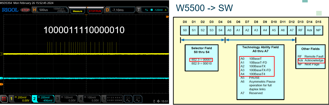
같은 방법으로 W5500의 FLP 파형 측정을 위해 UTP 케이블을 링크파트너 없이 연결하면
TX에서 아래와 같은 파형을 볼 수 있습니다.
W5500-EVB-PICO를 사용했고 FW은 넣지 않았습니다.
1000011110000000 비트는 또 아래와 같이 해석됩니다.
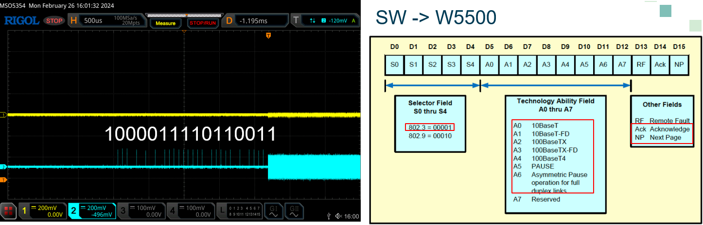
W5500과 iptime V504를 연결하여 link가 되는 순간을 측정하면 아래와 같습니다.
FLP 이후에 나오는 노이즈 같은 파형은 IDLE_SIGNAL 으로 자동협상을 정상적으로 마치고 패킷을 주고 받지 않을 때 링크 상태를 유지하기 위해 필요한 신호입니다.
빨간색으로 표시한 부분의 파형을 확대하여 분석하면 아래와 같습니다.
FLP만 측정하기 위하여 링크파트너 없이 연결했을때 와는 다르게 Ack비트가 1로 표시되는 것을 확인할 수 있습니다.
이는 링크파트너에서 FLP를 받았기 때문에 Ack가 활성화 된 것입니다.
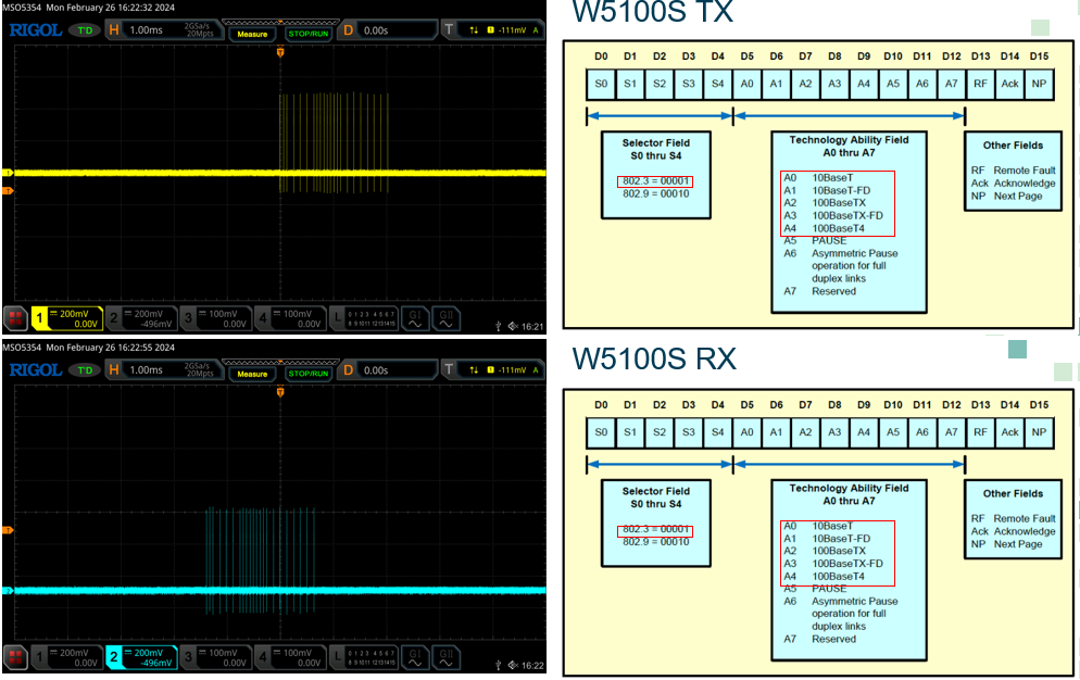
이번에는 W5100S-EVB-PICO를 측정해보겠습니다.
W5100S는 MDIX를 지원하기 때문에 FLP 파형을 TX에서만 발생시키는 W5500과는 달리 TX, RX 번갈아 가면서 발생시키고 있습니다.
다만 오실로스코프로 측정시 TX, RX 동시에 프로브를 연결하면 W5100S 내부 PHY에서 UTP 케이블 연결과 혼동하여 가끔 링크파트너가 연결되지도 않았는데 Link-UP이 동작하기도 하였습니다.
TX와 RX에서 나오는 FLP는 동일한 파형이며 위와 같은 뜻을 나타냅니다.
W5100S-EVB-PICO와 iptime V504의 link시 파형은 W5500과 동일하나 Auto MDIX기능으로 인해 TX와 RX가 바뀌기도 하였습니다.
이번 측정에서는 W5100S와 W5500이 어떻게 Auto-negotiation을 진행하는지 직접 파형을 측정해보았습니다.
다음 시간에는 MLT-3 방식으로 인코딩된 100base-t 신호를 측정하고 분석해보는 포스팅을 작성해 보겠습니다.