
10Base-T Ethernet decording
10Base-T Ethernet decording(1)
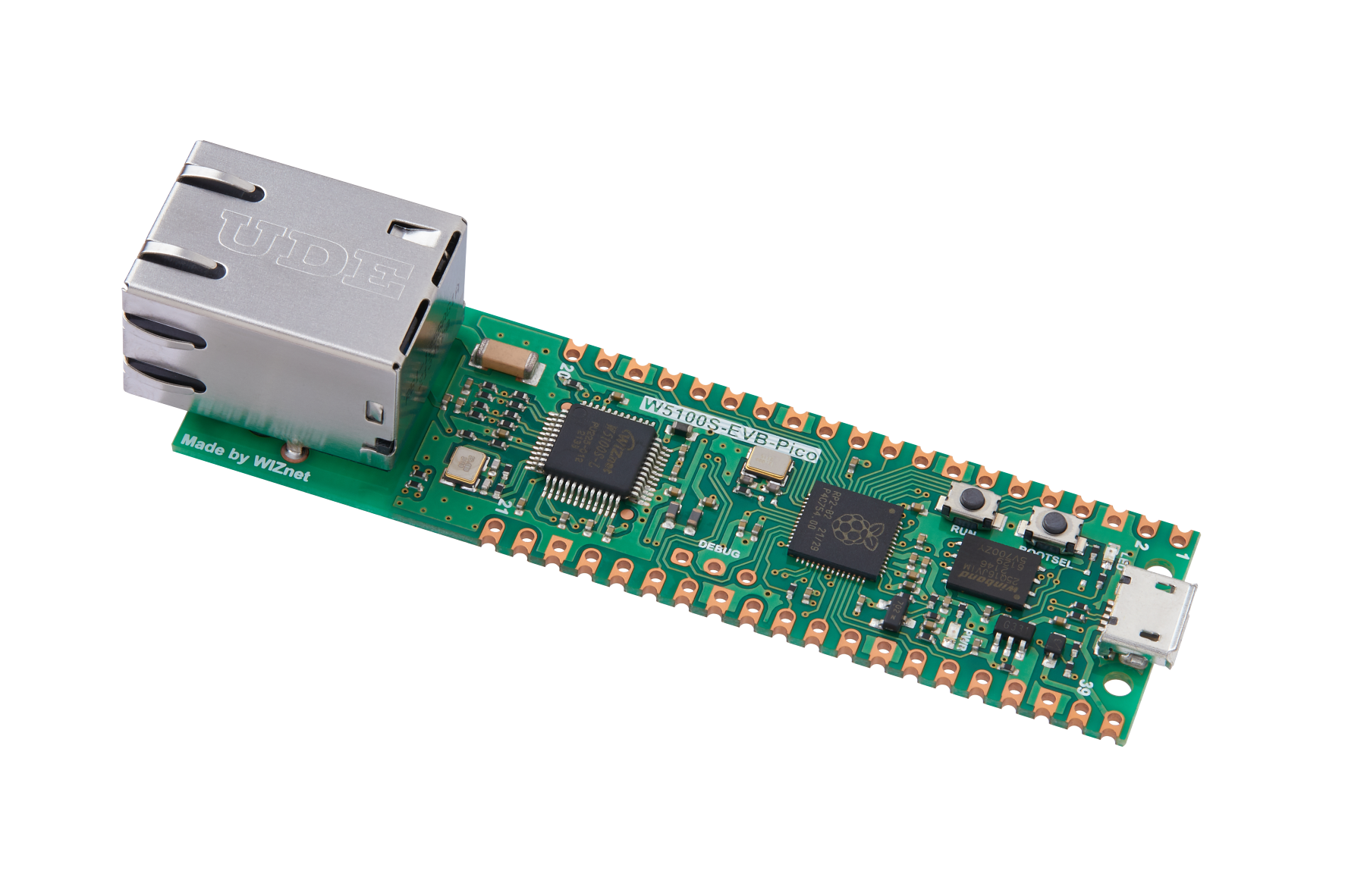
WIZnet - W5100S-EVB-Pico
x 1
Hi!
Today I will analyze the linkup process of 10Base-T and how data is sent by measuring the waveform directly.
The module used for the measurement is W5100S-EVB-PICO, set to 10M half instead of Auto negotiagion, and used the TCP loopback server example.
Note that 10Base-t uses Normal Link Pulse (NLP), unlike 100Base-t which uses Fast Link Pulse (FLP).
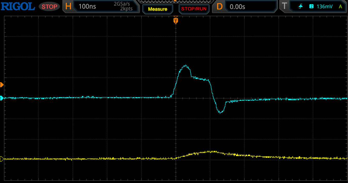
The blue waveform is the TX of the W5100S-EVB-PICO and the yellow is the RX.
The NLP's waveform has a 100 ns period and NLPs are sent every 16 ms±8 ms.
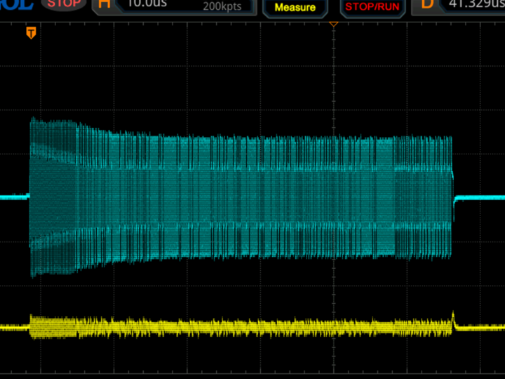
When packets are sent after becoming a link, they must be sent after the Preamble (PRE) waveform and Start of Frame Delimiter (SFD) waveform are generated before the packet is sent.
The PRE waveform is a 7Byte (56bit) long "10101010..." bit pattern and serves the following purposes
1. clock synchronization: The main purpose of the preamble is to synchronize the receiver's clock with the transmitter's clock, which is essential for accurate data exchange with other devices on the network. In the Manchester encoding method, each bit of data has either a rising or falling edge, and these transitions allow the clock signal to be extracted and accurate timing to be maintained.
2. Signal detection and stabilization: Preambles also allow network equipment to detect the start of a signal and prepare for it. Especially if the equipment has not received a signal for a long time, preambles help ensure that the receiving circuitry is activated and ready to handle the upcoming signal.
3. Identification of the start of the frame: The SFD that follows the preamble informs the receiver of the actual start of the data in the Ethernet frame. This clarifies when the receiver can accurately identify and begin processing the data portion of the frame.
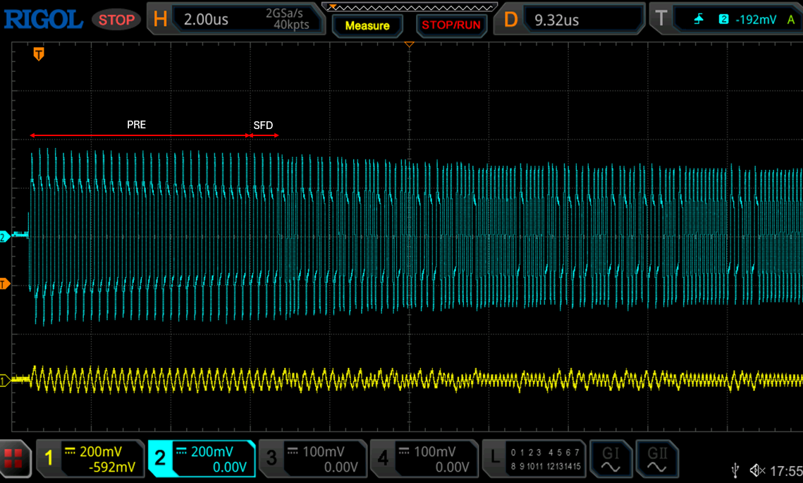
At the beginning of the waveform above are PRE and SFD.
However, to read the above waveform as bits, we need to understand the Manchseter Encode method used by 10Base-T to transmit data.
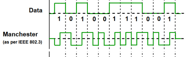
The Manchseter Encode method is to encode data bits using the rising edge (change from 0 to 1) and falling edge (change from 1 to 0) of the signal. Manchester encoding combines a clock signal and a data signal and transmits them as one signal. The advantage of this approach is that the clock information can be extracted from the signal itself.
10base-t has a transmission rate of 10 Mbps, which means that one bit must be transmitted at a rate of 100 ns.
Using the Manchseter Encode method, we can analyze the PRE preamble of the W5100S measured above.
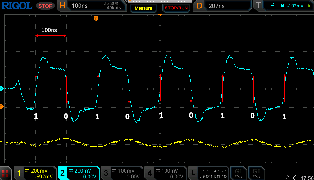
You can see that the waveform repeats 101010 as described earlier.
The full waveform of the PRE and SFD looks like this
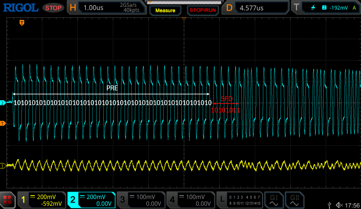
You can see the SFD waveform of "10101011" immediately followed by a 7 Byte (56 bit) long PRE repeating 10101010
The PRE and SFD waveforms are followed by the Destination MAC and Source Mac Ethernet type, Data, and Frame Check Sequence (FCS) waveforms.
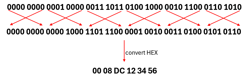
The Mac of the W5100S-EVB-PICO is 00:08:DC:12:34:56 and the Mac of the connected Client is 50:EB:F6:E6:5B:F8.
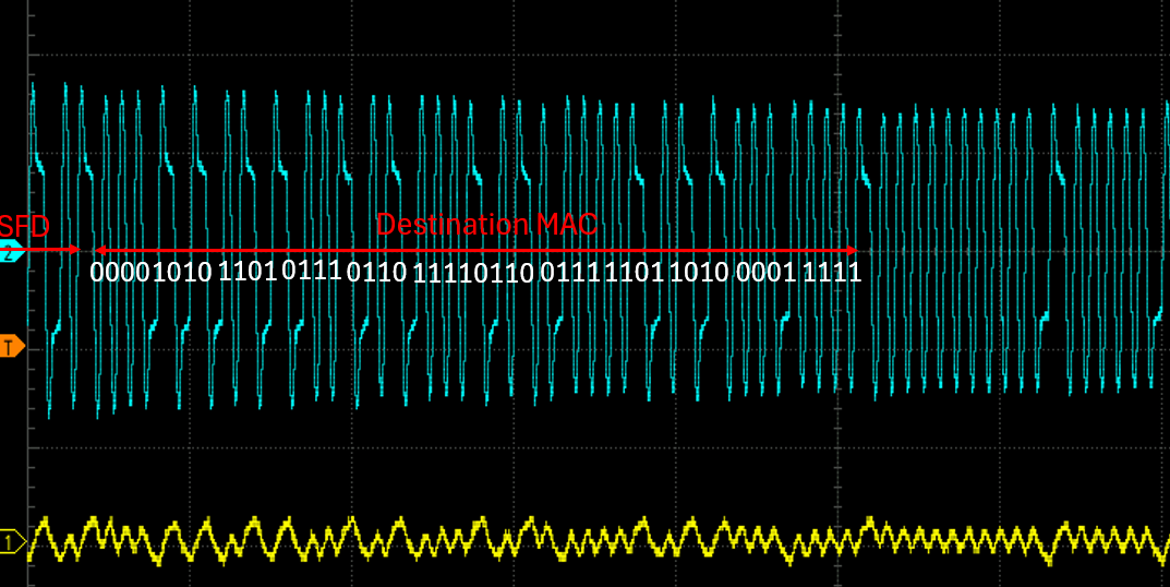
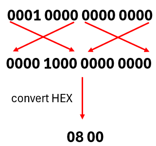
The Destination MAC reads "0000 1010 1101 0111 0110 1111 0110 0111 1101 1010 0001 1111", which is flipped and converted to HEX to get the Destination MAC.
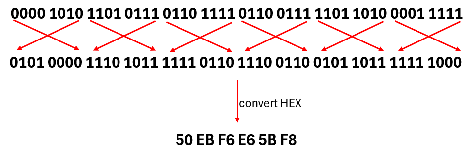
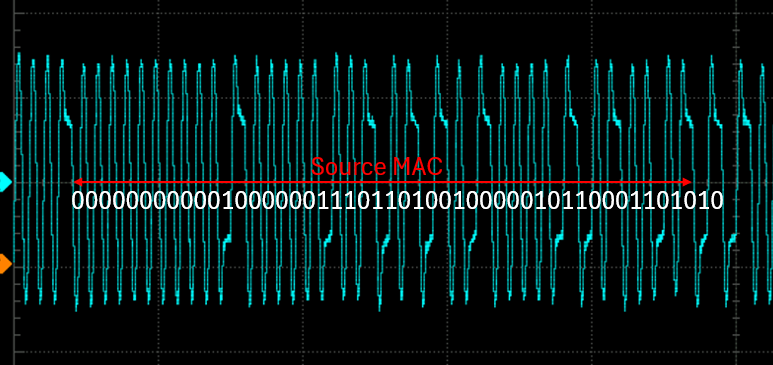
You can also read the Source MAC in the same way.
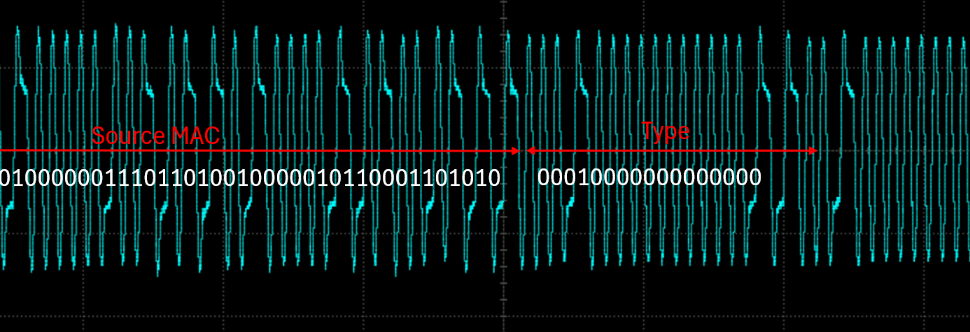
For Ethernet Type, you can read it the same way to determine IPv4.
The waveform that is measured afterward is the Data waveform, and analyzing that waveform will reveal the protocol used, Src IP, Dst IP, Src Port, Dst Port, etc.
But I'll analyze the Data waveform next time.
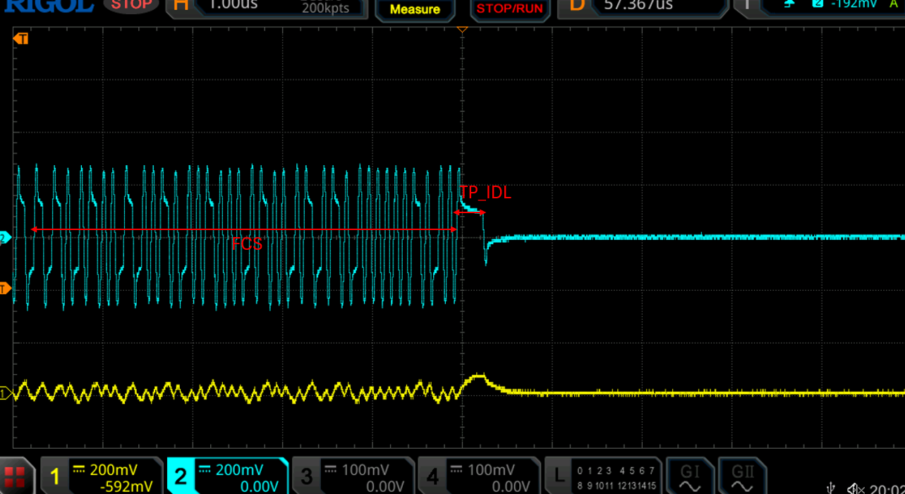
The 4 bytes (32 bits) at the end of the waveform are the Frame Check Sequence (FCS) and TP_IDL waveform measurements.
The FCS checks for data errors with the CRC-32 Checksum algorithm.
The TP_IDL signal always occurs after the FCS to signal the end of the FCS and holds 1 for at least 250 ns.
In this article, you learned how to analyze the data waveforms sent by the W5100S to see what happens to the link when it is running on 10Base-T.
Next time, I will analyze the data waveforms that were not covered in this article to check the protocol and other settings, and to see how the CRC-32 checksum used by FCS detects data errors.
Thanks for reading!
안녕하세요.
오늘은 10Base-T의 링크업 과정과 데이터를 어떤 방식으로 보내는지 직접 파형을 측정하여 분석해보도록 하겠습니다.
측정에 사용된 모듈은 W5100S-EVB-PICO이며 Auto negotiagion이 아닌 10M half로 세팅하였고 TCP loopback server 예제를 사용했습니다.
10Base-t는 FLP(Fast Link Pulse)를 사용하는 100Base-t와 다르게 NLP(Normal Link Pulse)를 사용합니다.
파란색 파형이 W5100S-EVB-PICO의 TX이고 노란색이 RX 입니다.
NLP의 파형은 100ns 주기를 갖고 NLP는 16ms±8ms 마다 보내집니다.
Link가 된 이후에 패킷이 보내질 때에는 반드시
Preamble(PRE) 파형과 Start of Frame Delimiter(SFD) 파형이 생성된 이후에 패킷을 보내게 됩니다.
PRE 파형은 7Byte(56bit)길이의 "10101010..." 비트 패턴이고 아래와 같은 역할을 합니다.
1. 클록 동기화: 프리앰블의 주된 목적은 수신기의 클록과 송신기의 클록을 동기화하는 것입니다. 이는 네트워크 상의 다른 장치들과 데이터를 정확하게 교환하기 위해 필수적입니다. 맨체스터 인코딩 방식에서는 데이터의 각 비트가 상승 에지 또는 하강 에지를 가지므로, 이러한 전환을 통해 클록 신호를 추출하고 정확한 타이밍을 유지할 수 있습니다.
2. 신호 감지 및 안정화: 프리앰블은 또한 네트워크 장비가 신호의 시작을 감지하고 이에 대비할 수 있도록 합니다. 특히, 장비가 오랫동안 신호를 받지 않았을 경우, 프리앰블은 수신 회로가 활성화되고 다가오는 신호를 처리할 준비를 할 수 있도록 하는 데 도움을 줍니다.
3. 프레임 시작의 식별: 프리앰블 뒤에 오는 SFD는 수신기에게 이더넷 프레임의 실제 데이터 시작을 알립니다. 이는 수신기가 프레임의 데이터 부분을 정확히 식별하고 처리하기 시작할 수 있는 시점을 명확하게 합니다.
위 파형의 앞부분에는 PRE와 SFD가 있습니다.
하지만 위 파형을 bit로 읽으려면 10Base-T에서 데이터 전송시 사용하는 Manchseter Encode방식을 이해해야 합니다.
Manchseter Encode 방식은 데이터 비트를 신호의 상승 에지(0에서 1로의 변화)와 하강 에지(1에서 0으로의 변화)를 사용하여 인코딩하는 것입니다. 맨체스터 인코딩은 클록 신호(clock signal)와 데이터 신호(data signal)를 결합하여 하나의 신호로 전송합니다. 이 방식의 장점은 신호 자체에서 클록 정보를 추출할 수 있다는 장점이 있습니다.
10base-t의 전송 속도는 10Mbps이고 이는 1비트가 100ns의 속도로 전송되어야 함을 의미합니다.
Manchseter Encode 방식을 사용하여 위에 측정한 W5100S의 PRE 앞부분을 분석해보면 아래와 같습니다.
앞서 설명드린대로 101010이 반복되는 파형을 볼 수 있습니다.
PRE와 SFD 전체 파형을 보면 아래와 같습니다.
10101010이 반복되는 7Byte(56bit) 길이의 PRE가 있고
바로 뒤에 "10101011" 의 SFD 파형을 확인할 수 있습니다.
PRE와 SFD 파형 뒤에는 차례대로 Destination MAC과 Source Mac 이더넷 type, Data, FCS(Frame Check Sequence) 파형이 나옵니다.
W5100S-EVB-PICO의 Mac은 00:08:DC:12:34:56이고 연결된 Client의 Mac은 50:EB:F6:E6:5B:F8 입니다.
Destination MAC은 "0000 1010 1101 0111 0110 1111 0110 0111 1101 1010 0001 1111"가 읽히는데 이를 뒤집어서 HEX로 변환하면 Destination MAC 이 나오게 됩니다.
같은 방법으로 Source MAC도 읽을 수 있습니다.
Ethernet Type의 경우도 같은 방법으로 읽으면 IPv4를 확인할 수 있습니다.
이후 측정되는 파형은 Data 파형으로 해당 파형을 분석하면 사용한 프로토콜, Src IP, Dst IP, Src Port, Dst Port 등을 알 수 있지만 본 문서에서는 생략하겠습니다.
파형의 끝 부분의 4byte(32 bit)는 Frame Check Sequence(FCS)와 TP_IDL 파형이 측정됩니다.
FCS는 CRC-32 Checksum 알고리즘으로 데이터 에러를 확인합니다.
TP_IDL 신호는 항상 FCS 뒤에 발생하여 FCS의 끝을 알려주는 신호이고 최소 250ns 동안 1을 유지합니다.
이번 시간에는 W5100S가 10Base-T로 구동시 링크는 어떻게 되는지 보내지는 데이터 파형은 어떻게 분석하는지에 대하여 알아보았습니다.
다음 시간에는 본문에서 다루지 않았던 Data 파형을 분석하여 프로토콜 및 기타 세팅을 확인하고 FCS에서 사용되는 CRC-32 Checksum이 어떻게 데이터 에러를 검출하는지 알아보겠습니다.
감사합니다!