
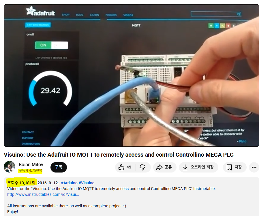
Visuino: Use the Adafruit IO MQTT to remotely access and control Controllino MEGA PLC
Controllino is an industry-ready Arduino PLC supported by Visuino. With MQTT via Adafruit IO, you can quickly build and deploy powerful automation projects.
Author

Project Overview
This UCC introduces the Controllino PLC—an industry-ready, open-source Arduino-based controller available in MINI, MAXI, and MEGA versions. Unlike typical Arduino boards, Controllino provides certified, robust features such as built-in RTC, relay outputs, RS485, and Ethernet, making it a practical low-cost PLC solution for industrial use.
Visuino fully supports Controllino, and the combination of industrial-grade hardware with visual programming enables rapid development of complex automation projects. After adding MQTT support to Visuino, the author created a tutorial using Controllino and Adafruit IO as the MQTT server. Users must create an Adafruit IO account and set up two MQTT feeds—“onoff” and “photocell.” The only recommended change is to set the “photocell” feed’s maximum value to 100 instead of 1024.
Project Description
Step 1: Components
- One Controllino MEGA PLC
- One Photoresistor Sensor module I got from this cheap 37 sensors set
- 3 Female-Female jumper wires

Step 2: Connect the Photoresistor Sensor to Controllino MEGA
- Connect Ground(Black wire), Power(Red wire), and Signal(Gray wire) to the Photoresistor Module
- Connect the other end of the Power wire(Red wire) to the 5V power pin of the Controllino MEGA
- Connect the other end of the Ground wire(Black wire) to the Ground pin of the Controllino MEGA
- Connect the other end of the Signal wire(Gray wire) to the Analog pin 0 of the Controllino MEGA
- You can see the Controllino MEGA Pinout here – http://controllino.biz/wp-content/uploads/2016/02/CONTROLLINO-MEGA-PINOUT-09-02-16.pdf
 |  |
 |  |
 |
Step 3: Start Visuino, and Select the Arduino Board Type
The Visuino also needs to be installed.
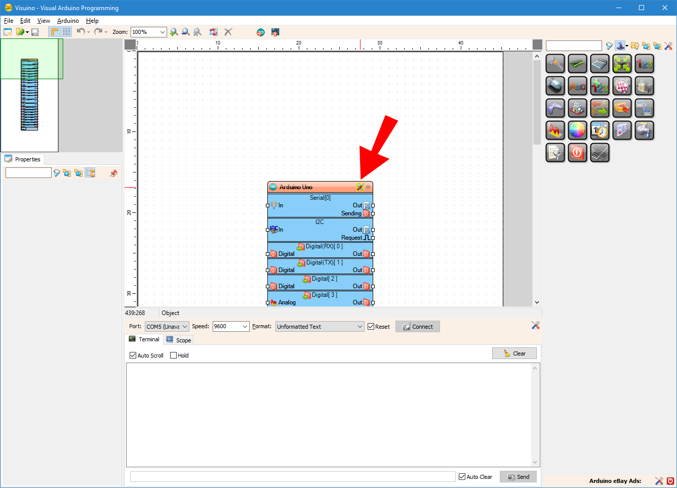
- Start Visuino as shown in the first picture
- Click on the “Tools” button on the Arduino component (Picture 1) in Visuino
- When the dialog appears, select Controllino MEGA as shown in Picture 2

Step 4: In Visuino: Configure the Ethernet, and Add Client Socket for the MQTT
First we need to assign MAC address to the Ethernet controller, and add a TCP/IP Client socket so we can connect to the Adafruit IO trough MQTT:
- In the Object Inspector expand the “Modules” property, then its “Ethernet” sub-property, and set the value of the “Mac Address” sub-property to some MAC address. I used “DE-AD-BE-EF-FE-ED“, but you should probably use a MAC generator.
- In the Object Inspector, click on the “…” button next to the value of the “Sockets” sub property of the “Ethernet” property (Picture 2)
- In the Sockets editor select “TCP/IP Client”, and then click on the “+” button (Picture 2) to add one (Picture 3)
- In the Object Inspector set the value of the “Host” property to “io.adafruit.com” (Picture 4)
- In the Object Inspector set the value of the “Port” property to “1883” (Picture 4)
- Close the “Sockets” dialog


Step 5: In Visuino: Add and Connect MQTT Client Component
Next we need to add and connect MQTT component:
- Type “mqtt” in the Filter box of the Component Toolbox then select the “MQTT Client” component (Picture 1), and drop it in the design area
- Connect the “Out” output pin of the “Modules.Ethernet.Sockets.TCP Client1” element of the “Controllino MEGA” component to the “In” input pin of the MQTTClient1 component (Picture 2)
- Connect the “Out” output pin of the MQTTClient1 component to the “In” input pin of the “Modules.Ethernet.Sockets.TCP Client1” element of the “Controllino MEGA” component (Picture 3)
- Connect the “Connected” output pin of the “Modules.Ethernet.Sockets.TCP Client1” element of the “Controllino MEGA” component to the “Connected” input pin of the MQTTClient1 component (Picture 2)
- Connect the “Disconnect” output pin of the MQTTClient1 component to the “Disconnect” input pin of the “Modules.Ethernet.Sockets.TCP Client1” element of the “Controllino MEGA” component (Picture 3)


Step 6: In Visuino: Configure the MQTT Client Component to Connect to Your Adafruit.IO Account
We need to specify the User Name and Password(Key) for the MQTT. We will copy them from the Adafruit IO account, so the Controllino can connect to it:
- Follow the instructions at “Where to find your adafruit.io key” from this Adafruit tutorial to find your Adafruit.IO Key, and copy it (Picture 1)
- In the Object Inspector paste the Key as a value of the “Password” property (Picture 2)
- In the object inspector set the value of the “User Name” property to your Adafruit User Name (Picture 3)


Step 7: In Visuino: Add and Configure 2 Text Topics to the The MQTT Client Component
Next we need to add 2 Topics to the MQTT Client for the 2 Adafruit.IO feeds – photocell and onoff:
- Click on the “Tools” button of the MQTTClient1component
- In the “Topics” editor select the “Text” element, and then click 2 times on the “+” button on the left (Picture 2) to add 2 Text Topics
- Select the first Topic element
- In the Object Inspector for the value of the “Topic” property, enter your Adafruit User Name, followed by the “/feeds/onoff”
- Select the second Topic element
- In the Object Inspector for the value of the “Topic” property, enter your Adafruit User Name, followed by the “/feeds/photocell”
- Close the “Characteristics” editor


Step 8: In Visuino: Add and Connect Compare Text Value Component
The Adafruit IO MQTT sends “ON” and “OFF” strings through the “onoff” feed. We need to convert it to digital signal. To do this we will use a “Compare Text Value” component to compare the text with “ON”:
- Type “compare” in the Filter box of the Component Toolbox then select the “Compare Text Value” component (Picture 1), and drop it in the design area
- In the Object Inspector, set the value of the “Value” property of the CompareTextValue1 component to “ON”
- Connect the “Out” pin of the “Topics.Text Topic1” element of the MQTTClient1 (Picture 3) to the “In” pin of the CompareTextValue1
- Connect the “Out” output pin of the CompareTextValue1 to the “Digital” input pin of the “Digital[ 2 ]” channel of the Controllino MEGA component


Step 9: In Visuino: Add and Connect Analog Snapshot, and Clock Generator Components
We don’t want to send data through MQTT all the time. This can overwhelm the network. Instead we will take a snapshot of the data once a second, with an “Analog Snapshot” component:
- Type “snapshot” in the Filter box of the Component Toolbox then select the “Analog Snapshot” component (Picture 1), and drop it in the design area
- Connect the “Out” output pin of the AnalogSnapshot1 component to the “In” input pin of the “Topics.Text Topic2” element of the MQTTClient1 component (Picture 2)
- Type “clock” in the Filter box of the Component Toolbox then select the “Clock Generator” component (Picture 3), and drop it in the design area
- Connect the “Out” output pin of the ClockGenerator1 component to the “Snapshot” input pin of the AnalogSnapshot1 component (Picture 4)


Step 10: In Visuino: Add, Connect and Configure Multiply by Value Component
The Analog 0 channel provides data between 0.0 and 1.0. It is better to convert it to values between 0 and 100 for the Adafruit.IO, so we will multiply it by 100:
- Type “multip” in the Filter box of the Component Toolbox then select the “Multiply By Value” component (Picture 1), and drop it in the design area
- In the Object Inspector, set the value of the “Value” property to “100” (Picture 2)
- Connect the “Out” output pin of the MutiplyByValue1 component to the “In” input pin of the AnalogSnapshot1 component (Picture 3)
- Connect the “In” input pin of the MutiplyByValue1 component (Picture 4) to the “Out” output pin of the “Analog[ 0 ]” channel of the Controllino MEGA component (Picture 5)


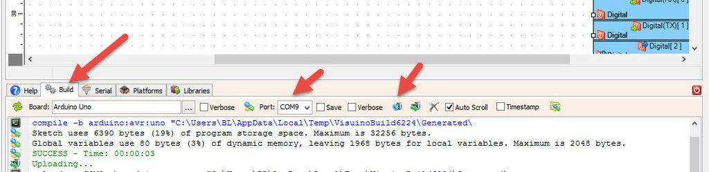
Step 11: Generate, Compile, and Upload the Arduino Code
In Visuino, at the bottom click on the “Build” Tab, make sure the correct port is selected, then click on the “Compile/Build and Upload” button.
Step 12: And Play…
Congratulations! You have completed the project.
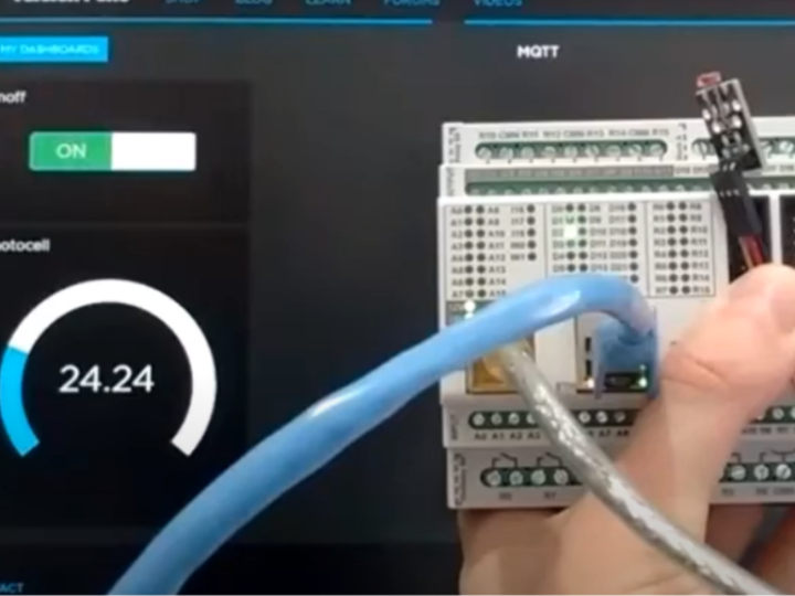
From a computer or a mobile device start a web browser, login to your Adafruit IO account, and then navigate to open the stream that you have created following this Adafruit IO tutorial (Picture 1)
On the Video you can see the Controllino MEGA‘s LED being controlled, and the value of the Photoresistor displayed through a web browser on a PC and Android Tablet..
As shown in the Video, you can control the LED on the Digital 2 pin with the On/Off Switch, and monitor the values from the Photoresistor on the Gauge.
On Picture 2 you can see the connected Controllino MEGA controlled by an Android Tablet.
On Picture 3 you can see the complete Visuino diagram.
Also attached is the Visuino project, that I created for this Tutorial. You can download and open it in Visuino.


