
Telechips-ADAS-Project
ADAS prototype: STM32+RPi FreeRTOS control (SCC/LFA/MCB), ported to a Telechips VCP-G board with W5500 Ethernet. Educational project.

WIZnet - W5500
x 1
2차: Ethernet 통신(센서/제어 신호 실시간 전송)
이 프로젝트는 @SeungHyuk-Jin이 진행한 텔레칩스 부트캠프 프로젝트 입니다. 데모 환경에서 시연한 교육용 ADAS 프로토타입이며, 실제 차량 안전 시스템이 아닙니다.
프로젝트가 하는 일
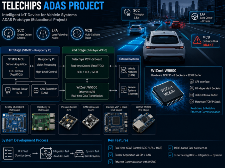
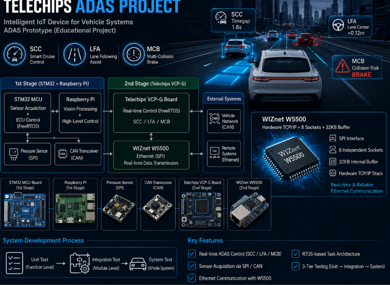
Telechips ADAS Project는 "차량 시스템을 위한 지능형 IoT 장치 → 사고 예방 운전 보조 시스템(ADAS Prototype)"을 목표로, 두 단계에 걸쳐 개발한 프로젝트입니다.
- 1차 (STM32 + Raspberry Pi 기반): STM32가 센서 데이터 수집과 제어를, Raspberry Pi가 영상 처리와 상위 제어 로직을 담당합니다. STM32 + FreeRTOS로 중앙 ECU 제어 구조를 설계하고, 핵심 ADAS 기능(SCC/LFA/MCB)을 실시간 Task 단위로 구현했습니다. CAN 통신으로 차량 네트워크 일부를 구성하고, 압력 센서를 SPI로 읽어 페달 입력 모듈을 만들었습니다.
- 2차 (Telechips 보드 포팅 및 최적화): 1차의 STM32 기반 시스템을 Telechips 차량용 플랫폼(VCP-G 보드)으로 포팅하고, FreeRTOS 기반으로 재구성해 실시간 성능을 개선했습니다. 이 단계에서 W5500 기반 Ethernet 통신 구조를 설계·적용해 센서 데이터와 제어 신호를 실시간 전송합니다.
| Component | Notes |
|---|---|
| STM32 MCU 보드 | 1차: 센서 수집 + FreeRTOS 중앙 제어(ECU) |
| Raspberry Pi | 1차: 영상 처리 + 상위 제어 로직 |
| 압력 센서 (SPI/spidev) | 가속/브레이크 페달 입력 모듈 |
| CAN 트랜시버 | 차량 네트워크(CAN) 메시지 송수신 |
| Telechips VCP-G 보드 | 2차: 차량용 플랫폼 포팅 대상 |
| WIZnet W5500 | 2차: Ethernet 통신(센서/제어 신호 실시간 전송) |
핵심 ADAS 기능 (1차)
- SCC (Smart Cruise Control, 차간거리 제어): 전방 거리 기반 속도 제어, timegap을 사용한 안전 거리 유지 로직.
- LFA (Lane Following Assist, 차선 유지 보조): 차로 중앙 유지, 차선 중심 오프셋 계산 및 조향 제어.
- MCB (Multi-Collision Brake, 충돌 방지 제동): 충돌 상황 판단 기반 제동, 시스템 상태에 따른 긴급 제어.
전체 제어 흐름은 "센서 입력 → 제어 판단 → 출력(속도/조향/제동)"으로 구성되며, 압력 센서 값은 SPI(spidev)로 실시간 수집해 가속/브레이크 신호로 변환하고 임계값 필터링을 적용합니다.
WIZnet이 들어가는 위치
이 프로젝트에서 사용되는 WIZnet 제품은 W5500이며, 2차(Telechips 보드 포팅) 단계에서 적용됩니다.
W5500은 Telechips VCP-G 보드의 Ethernet 통신 구조를 담당합니다. ADAS처럼 센서 데이터와 제어 신호를 실시간으로 주고받아야 하는 시스템에서는 통신 지연·끊김이 곧 제어 품질로 직결됩니다. W5500은 하드웨어 TCP/IP 스택, SPI 인터페이스, 8개 독립 socket, 32KB 내부 buffer를 제공하므로, RTOS가 제어 Task에 집중하는 동안 네트워크 처리를 오프로드해 실시간 전송 구조를 안정적으로 구현할 수 있습니다.
역할을 나누면 다음과 같습니다.
- STM32 / Telechips 보드 (제어): FreeRTOS 기반 실시간 제어 Task(SCC/LFA/MCB), 센서 처리
- Raspberry Pi (1차, 영상): 영상 처리 및 상위 제어 로직
- CAN (차량 네트워크): 차량 메시지 송수신
- W5500 (2차, Ethernet): 센서/제어 신호의 실시간 네트워크 전송
notion : https://app.notion.com/p/TOPST-VCP-G-W5500-256697796dab81acbae6fe6c3aa2043b
구현 메모
- RTOS 구조: SCC/LFA/MCB를 Task 단위로 분리하고 우선순위를 구성해 실시간 제어가 가능하도록 설계.
- 페달 입력 모듈: SPI(spidev)로 압력 센서를 읽어 가속/브레이크 입력으로 변환, 일정 주기 전송 + 임계값 필터링.
- 통신 구조: 1차는 CAN 일부 적용, 2차는 W5500 Ethernet으로 실시간 전송 구조 구현.
- 검증: 단위 테스트(기능 단위) → 통합 테스트(모듈 간 연동) → 시스템 테스트(전체 시스템)의 3단계 테스트로 검증.
저장소에는 유스케이스/요구사항/아키텍처 다이어그램, 테스트케이스 표, 실행 결과(SCC/LFA/MCB) 스크린샷이 포함되어 있습니다.
TOPST VCP-G에서 W5500 이더넷 올리기 (구현 상세)
2차 단계에서 Telechips TOPST VCP-G 보드에 이더넷을 붙이는 과정에서, 물리 이더넷(RMII/MII) 대신 W5500(SPI 기반) 을 선택했습니다. 그 이유와 구현 과정을 정리합니다.
왜 RMII/MII가 아니라 W5500(SPI)인가
| 방식 | 특징 |
|---|---|
| RMII/MII 직접 연결 | TXD0~3, RXD0~3, TX_EN, RX_DV, CRS, COL, REF_CLK, MDIO, MDC 등 다수의 물리 신호선을 MCU가 직접 제어. 핀 MUX 설정, REF_CLK 타이밍 정합, MDIO로 PHY 레지스터를 직접 읽고 쓰며 링크/속도/듀플렉스까지 수동 관리 필요. |
| W5500 (SPI) | 칩 내부에 MAC + PHY + TCP/IP 스택이 통합. SPI 4~5선(SCLK, MOSI, MISO, CS, INT)만 사용하고, 물리 신호·PHY 링크·패킷·TCP/IP는 칩이 자동 처리. MCU는 "레지스터 기반 데이터 송수신"만 수행. |
결론적으로 W5500을 쓰면 MCU 펌웨어는 네트워크 제어가 아니라 SPI로 레지스터를 읽고 쓰는 것에만 집중하면 되므로, 차량용 SoC에 이더넷을 올리는 부담이 크게 줄어듭니다.
핀 연결
| 신호 | 핀/설명 |
|---|---|
| SPI SCLK | 3번 |
| SCS (CS) | GPIO_B(11) — 평상시 high, low가 되면 칩 레지스터 접근 권한(송수신 가능) |
| SPI MOSI (MCU→W5500) | 4번 |
| SPI MISO (W5500→MCU) | 1번 |
| INT (송수신 시 인터럽트) | GPIO_B(10) |
| RST | 기본 active high 유지 (10KΩ 풀업 + 3.3V) |
| 전원 | 3.3V, GND |
ioLibrary 설정
W5500 구동에는 WIZnet의 ioLibrary_Driver를 사용합니다(W 시리즈 코드 + 소켓/인터넷 코드 포함).
# topst-vcp/sources/app.sample/app.base 폴더에서 git clone https://github.com/Wiznet/ioLibrary_Driver.gitrules.mk의 경로/소스를 W6300이 아닌 W5500 기준으로 바꾸고(VPATH·INCLUDES의 Ethernet/W5500, SRCS에 w5500.c, socket.c, wizchip_conf.c, w5500_port.c 등), wizchip_conf.h에서 칩과 IO 모드를 W5500으로 설정합니다.
// wizchip_conf.h
#define _WIZCHIP_            W5500            // 기본값이 W6300으로 되어 있으면 W5500으로 변경
#define _WIZCHIP_IO_MODE_ _WIZCHIP_IO_MODE_SPI_VDM_ // VDM 모드- VDM(Variable Data Length Mode): CS가 low인 동안 원하는 만큼 바이트를 연속 송수신.
- FDM(Fixed Data Length Mode): 정해진 길이(N바이트) 단위로 접근, 소량 레지스터 접근에 적합.
라이브러리 계층 관계는 다음과 같습니다.
[ 애플리케이션 ]
      │
   socket.c       ← 고수준 소켓 API
      │
   w5500.c        ← 레지스터·버퍼 제어 (저수준)
      │
 wizchip_conf.c   ← SPI/GPIO 콜백 등록 & 칩 설정
      │
  HAL/SPI 드라이버 (사용자 구현)
Telechips 고속 전송: ECCP (DMA + SPI)
Telechips SoC는 외부 칩(W5500)과 데이터를 주고받을 때 단순 폴링이 아니라 ECCP(Embedded Chip-to-Chip Protocol) 로 DMA를 활용해 고속 전송합니다. 내부적으로 GPSB(General-purpose SPI Bus) 컨트롤러와 연동되어, 버퍼↔SPI 레지스터 간 대량 전송을 CPU 개입 없이 DMA가 수행하고 완료 시 ECCP_Complete 콜백으로 알립니다.
#define ECCP_GPSB_DMA_SIZE   1024U        // DMA 전송 버퍼 크기(바이트)
#define ECCP_GPSB_SPEED      10000000UL   // SPI 클럭 10MHz
#define ECCP_GPSB_BPW        8UL          // 전송 폭 8bit
포트 레이어 (w5500_port) 핵심
ioLibrary가 호출할 SPI/CS 콜백을 등록하고, FreeRTOS 환경에서 SPI/칩 접근이 겹치지 않도록 뮤텍스를 사용합니다.
// CS 핀 제어 (low일 때 칩 선택)
void wizchip_select(void)   { GPIO_Set(W5500_CS_GPIO, 0); }
void wizchip_deselect(void) { GPIO_Set(W5500_CS_GPIO, 1); }

// 콜백 등록 + 칩 초기화
void W5500_Port_Init(void) {
    reg_wizchip_cs_cbfunc(wizchip_select, wizchip_deselect);
    reg_wizchip_spi_cbfunc(wizchip_spi_readbyte_cb, wizchip_spi_writebyte_cb);
    reg_wizchip_spiburst_cbfunc(wizchip_spi_readburst_cb, wizchip_spi_writeburst_cb);

    uint8_t txsize[8] = {2,2,2,2,2,2,2,2};   // 소켓별 2KB
    uint8_t rxsize[8] = {2,2,2,2,2,2,2,2};
    wizchip_init(txsize, rxsize);
}

// 정적 네트워크 설정
void W5500_Init_DefaultNet(void) {
    wiz_NetInfo netinfo = {
        .mac = {0x00,0x08,0xDC,0x12,0x34,0x56},
        .ip  = {192,168,2,28}, .sn = {255,255,255,0},
        .gw  = {192,168,2,1},  .dns = {8,8,8,8},
        .dhcp = NETINFO_STATIC
    };
    wizchip_setnetinfo(&netinfo);
}
초기화 시 getVERSIONR()로 칩 버전을 확인하고, getPHYCFGR()의 Link-up 비트를 폴링해 PHY 링크가 올라올 때까지 잠시 대기한 뒤 IP/MAC/속도(10/100Mbps)·듀플렉스를 디버그 출력합니다.
멀티 소켓 TCP 서버 구조 (포트 5001 / 5002 / 5003)
W5500의 독립 소켓을 활용해, 역할이 다른 3개의 TCP 서버 태스크를 FreeRTOS에서 동시에 운영합니다.
| 태스크 | 포트 | 역할 |
|---|---|---|
ETH0_Task | 5001 | 스위치/명령 수신 — 수신 문자로 SCC/LFA/방향/차간거리 플래그 토글 (!, @, #, $) |
ETH1_Task | 5002 | 차량 상태 송신 — speed/accel/brake/scc_flag/lfa_flag/scc_distance/dir_flag를 주기(500ms) 전송 |
ETH2_Task | 5003 | 영상/제어 보조 — lfa_flag·dir_flag 송수신 (Raspberry Pi 영상 측 연동) |
각 태스크는 socket() → listen() → (SOCK_ESTABLISHED) → recv()/send() → 연결 종료 시 재listen 패턴으로 동작하며, 모든 W5500 접근은 wiz_lock()/wiz_unlock() 뮤텍스로 보호됩니다.
전체 소스(rules.mk, wizchip_conf.h, w5500_port.h/.c 등)는 작성자 저장소/문서를 참고하세요. 위는 핵심 흐름을 발췌·요약한 것입니다.
유사 프로젝트
https://maker.wiznet.io/ssekim/projects/apache-nuttx-real-time-operating-system/
두 프로젝트는 모두 RTOS 기반 실시간 임베디드 시스템에서 Ethernet(W5500 계열) 연결을 활용한다는 점에서 유사합니다. 다만 Telechips ADAS Project는 차량 ADAS 기능(SCC/LFA/MCB)을 FreeRTOS로 구현하고 차량용 보드로 포팅한 응용 프로젝트이고, NuttX는 표준 준수·작은 풋프린트를 강조하는 범용 RTOS 자체입니다.
| 항목 | Telechips ADAS Project | Apache NuttX RTOS |
|---|---|---|
| 성격 | 차량 ADAS 응용 프로토타입 | 범용 RTOS |
| RTOS | FreeRTOS | NuttX |
| 핵심 기능 | SCC / LFA / MCB 제어 | POSIX 호환 커널 |
| 통신 | CAN(1차) + W5500 Ethernet(2차) | 일반 네트워크 스택 |
| 플랫폼 | STM32 → Telechips VCP-G | 다양한 MCU/SoC |
| W5500 사용 | 2차 Ethernet 통신 | 일반 네트워크 연결 |
FAQ
Q: 어떤 프로젝트인가요? A: STM32+Raspberry Pi로 ADAS(SCC/LFA/MCB)를 구현하고, 이를 Telechips 차량용 보드로 포팅·최적화한 교육용 ADAS 프로토타입입니다.
Q: W5500은 어디에 쓰이나요? A: 2차 Telechips 보드 포팅 단계에서 Ethernet 통신 구조에 사용되어, 센서 데이터와 제어 신호를 실시간 전송합니다.
Q: 실제 차량에 쓸 수 있나요? A: 아니요. 데모 환경에서 시연한 교육/부트캠프용 프로토타입이며, 실제 도로/차량 안전 시스템으로 사용하도록 만든 것이 아닙니다.
Q: ADAS 기능은 무엇을 포함하나요? A: SCC(차간거리 제어), LFA(차선 유지 보조), MCB(충돌 방지 제동) 세 가지입니다.
What the Project Does
Telechips ADAS Project is a two-phase project aiming at an "intelligent IoT device for vehicle systems → accident-prevention driver assistance system (ADAS prototype)."
- Phase 1 (STM32 + Raspberry Pi): The STM32 handles sensor data collection and control, while the Raspberry Pi handles image processing and high-level control logic. A central ECU control structure was designed with STM32 + FreeRTOS, and the core ADAS functions (SCC/LFA/MCB) were implemented as real-time tasks. Part of the vehicle network was built with CAN, and a pedal-input module was created by reading a pressure sensor over SPI.
- Phase 2 (Telechips board porting & optimization): The Phase 1 STM32-based system was ported to a Telechips automotive platform (VCP-G board) and restructured on FreeRTOS to improve real-time performance. In this phase, a W5500-based Ethernet communication structure was designed and applied to transmit sensor data and control signals in real time.
Core ADAS Functions (Phase 1)
- SCC (Smart Cruise Control): forward-distance-based speed control with safe-distance keeping using a timegap.
- LFA (Lane Following Assist): lane-center keeping, lane-center offset calculation, and steering control.
- MCB (Multi-Collision Brake): braking based on collision-situation judgment and emergency control by system state.
The overall flow is "sensor input → control decision → output (speed/steering/braking)." Pressure-sensor values are read in real time via SPI (spidev), converted into accel/brake signals, transmitted periodically, and filtered against thresholds.
Where WIZnet Fits
The WIZnet product used in this project is the W5500, applied in Phase 2 (Telechips board porting).
The W5500 provides the Ethernet communication structure of the Telechips VCP-G board. In a system like ADAS that must exchange sensor data and control signals in real time, communication latency/dropouts directly affect control quality. With its hardware TCP/IP stack, SPI interface, eight independent sockets, and 32 KB internal buffer, the W5500 offloads network processing so the RTOS can focus on control tasks while implementing a stable real-time transmission structure.
Role separation:
- STM32 / Telechips board (control): FreeRTOS real-time control tasks (SCC/LFA/MCB), sensor processing
- Raspberry Pi (Phase 1, vision): image processing and high-level control logic
- CAN (vehicle network): vehicle message exchange
- W5500 (Phase 2, Ethernet): real-time network transmission of sensor/control signals
Implementation Notes
- RTOS structure: SCC/LFA/MCB separated into tasks with configured priorities for real-time control.
- Pedal input module: pressure sensor read via SPI (spidev), converted to accel/brake input, periodic transmission + threshold filtering.
- Communication: Phase 1 partially uses CAN; Phase 2 implements real-time transmission over W5500 Ethernet.
- Verification: three-stage testing — unit tests (per function) → integration tests (module interplay) → system tests (whole system).
The repository includes use-case/requirements/architecture diagrams, test-case tables, and execution-result (SCC/LFA/MCB) screenshots. Adding those images to the DETAILS section greatly improves readability.
Bringing Up W5500 Ethernet on TOPST VCP-G (Deep Dive)
In Phase 2, when adding Ethernet to the Telechips TOPST VCP-G board, the W5500 (SPI-based) was chosen over a physical Ethernet (RMII/MII) interface. Here is why, and how it was implemented.
Why W5500 (SPI) instead of RMII/MII
| Approach | Characteristics |
|---|---|
| Direct RMII/MII | The MCU directly drives many physical signals (TXD0~3, RXD0~3, TX_EN, RX_DV, CRS, COL, REF_CLK, MDIO, MDC). Requires pin MUX setup, REF_CLK timing alignment, and manual control of link/speed/duplex by reading/writing PHY registers via MDIO. |
| W5500 (SPI) | MAC + PHY + TCP/IP stack are integrated in the chip. Uses only 4–5 SPI lines (SCLK, MOSI, MISO, CS, INT); the chip handles physical signals, PHY link, packets, and the TCP/IP stack. The MCU only does "register-based data transmit/receive." |
So with the W5500, the MCU firmware focuses on reading/writing registers over SPI rather than network control, greatly reducing the burden of putting Ethernet on an automotive SoC.
Pin connections
| Signal | Pin / Notes |
|---|---|
| SPI SCLK | 3 |
| SCS (CS) | GPIO_B(11) — normally high; pulling low grants register access (TX/RX enabled) |
| SPI MOSI (MCU→W5500) | 4 |
| SPI MISO (W5500→MCU) | 1 |
| INT (interrupt on TX/RX) | GPIO_B(10) |
| RST | keep active high (10 KΩ pull-up + 3.3 V) |
| Power | 3.3 V, GND |
ioLibrary setup
The W5500 is driven with WIZnet's ioLibrary_Driver (W-series code + socket/internet code).
# from topst-vcp/sources/app.sample/app.base git clone https://github.com/Wiznet/ioLibrary_Driver.gitChange the rules.mk paths/sources from W6300 to W5500 (VPATH/INCLUDES for Ethernet/W5500, and SRCS including w5500.c, socket.c, wizchip_conf.c, w5500_port.c), and set the chip and IO mode to W5500 in wizchip_conf.h.
// wizchip_conf.h
#define _WIZCHIP_            W5500            // change from W6300 if needed
#define _WIZCHIP_IO_MODE_ _WIZCHIP_IO_MODE_SPI_VDM_ // VDM mode- VDM (Variable Data Length Mode): transmit/receive any number of bytes continuously while CS is low.
- FDM (Fixed Data Length Mode): access in fixed N-byte units, suitable for small register access.
Library layering:
[ application ]
      │
   socket.c        ← high-level socket API
      │
   w5500.c         ← register/buffer control (low-level)
      │
 wizchip_conf.c    ← registers SPI/GPIO callbacks & chip config
      │
  HAL/SPI driver (user-implemented)
Telechips high-speed transfer: ECCP (DMA + SPI)
The Telechips SoC exchanges data with an external chip (W5500) not by simple polling but via ECCP (Embedded Chip-to-Chip Protocol), using DMA for high-speed transfer. Internally it works with the GPSB (General-purpose SPI Bus) controller, so the DMA performs bulk buffer↔SPI-register transfers without CPU involvement and signals completion through an ECCP_Complete callback.
#define ECCP_GPSB_DMA_SIZE   1024U        // DMA buffer size (bytes)
#define ECCP_GPSB_SPEED      10000000UL   // SPI clock 10 MHz
#define ECCP_GPSB_BPW        8UL          // 8 bits per word
Port layer (w5500_port) essentials
It registers the SPI/CS callbacks that ioLibrary calls, and uses FreeRTOS mutexes so SPI/chip access does not overlap.
// CS control (chip selected when low)
void wizchip_select(void)   { GPIO_Set(W5500_CS_GPIO, 0); }
void wizchip_deselect(void) { GPIO_Set(W5500_CS_GPIO, 1); }

// register callbacks + chip init
void W5500_Port_Init(void) {
    reg_wizchip_cs_cbfunc(wizchip_select, wizchip_deselect);
    reg_wizchip_spi_cbfunc(wizchip_spi_readbyte_cb, wizchip_spi_writebyte_cb);
    reg_wizchip_spiburst_cbfunc(wizchip_spi_readburst_cb, wizchip_spi_writeburst_cb);

    uint8_t txsize[8] = {2,2,2,2,2,2,2,2};   // 2KB per socket
    uint8_t rxsize[8] = {2,2,2,2,2,2,2,2};
    wizchip_init(txsize, rxsize);
}

// static network config
void W5500_Init_DefaultNet(void) {
    wiz_NetInfo netinfo = {
        .mac = {0x00,0x08,0xDC,0x12,0x34,0x56},
        .ip  = {192,168,2,28}, .sn = {255,255,255,0},
        .gw  = {192,168,2,1},  .dns = {8,8,8,8},
        .dhcp = NETINFO_STATIC
    };
    wizchip_setnetinfo(&netinfo);
}
At init, the chip version is checked with getVERSIONR(), and the Link-up bit of getPHYCFGR() is polled briefly until the PHY link is up, then IP/MAC/speed (10/100 Mbps)/duplex are printed for debugging.
Multi-socket TCP server structure (ports 5001 / 5002 / 5003)
Using the W5500's independent sockets, three TCP server tasks with different roles run concurrently under FreeRTOS.
| Task | Port | Role |
|---|---|---|
ETH0_Task | 5001 | Receives switch/commands — toggles SCC/LFA/direction/time-gap flags from received chars (!, @, #, $) |
ETH1_Task | 5002 | Sends vehicle status — periodically (500 ms) transmits speed/accel/brake/scc_flag/lfa_flag/scc_distance/dir_flag |
ETH2_Task | 5003 | Vision/control aux — exchanges lfa_flag·dir_flag (works with the Raspberry Pi vision side) |
Each task follows the socket() → listen() → (SOCK_ESTABLISHED) → recv()/send() → re-listen on disconnect pattern, and all W5500 access is protected by wiz_lock()/wiz_unlock() mutexes.
For the full source (rules.mk, wizchip_conf.h, w5500_port.h/.c, etc.), refer to the author's repository/documentation. The above is an excerpted summary of the key flow.
Similar Project
https://maker.wiznet.io/ssekim/projects/apache-nuttx-real-time-operating-system/
Both projects are similar in that they leverage Ethernet (W5500-class) connectivity in an RTOS-based real-time embedded system. However, the Telechips ADAS Project is an applied project implementing vehicle ADAS functions (SCC/LFA/MCB) on FreeRTOS and porting them to an automotive board, while NuttX is a general-purpose RTOS emphasizing standards compliance and a small footprint.
| Item | Telechips ADAS Project | Apache NuttX RTOS |
|---|---|---|
| Nature | Vehicle ADAS applied prototype | General-purpose RTOS |
| RTOS | FreeRTOS | NuttX |
| Core features | SCC / LFA / MCB control | POSIX-compatible kernel |
| Communication | CAN (Phase 1) + W5500 Ethernet (Phase 2) | General network stack |
| Platform | STM32 → Telechips VCP-G | Many MCUs/SoCs |
| W5500 usage | Phase 2 Ethernet communication | General network connectivity |
FAQ
Q: What is this project? A: An educational ADAS prototype that implements ADAS (SCC/LFA/MCB) on STM32 + Raspberry Pi, then ports and optimizes it onto a Telechips automotive board.
Q: Where is the W5500 used? A: In the Phase 2 Telechips porting stage, for the Ethernet communication structure that transmits sensor data and control signals in real time.
Q: Can it be used in a real vehicle? A: No. It is an educational/bootcamp prototype demonstrated in a demo environment, not built for real road/vehicle safety use.
Q: What ADAS functions are included? A: Three — SCC (smart cruise control), LFA (lane following assist), and MCB (multi-collision brake).