
Solar2MQTT: High-Reliability Solar Monitoring via ESP32-S3 Ethernet
ESP32-S3-based Solar2MQTT uses W5500 Ethernet to reliably collect inverter data and transmit it via MQTT to Home Assistant without Wi-Fi interruptions.
1.Summary
태양광 발전 시스템은 실외나 전기실 등 네트워크 환경이 가혹한 곳에 설치되는 경우가 많습니다. 기존의 Wi-Fi 방식은 벽이나 거리 문제로 데이터 누락이 발생하거나 연결이 끊길 위험이 큽니다.
본 프로젝트는 WIZnet W5500 이더넷 컨트롤러가 탑재된 Waveshare ESP32-S3-ETH 보드를 사용하여, 24시간 끊김 없는 데이터 전송을 보장하는 Solar2MQTT 시스템을 구축한 사례입니다. 태양광 인버터의 데이터를 실시간으로 수집해 MQTT를 통해 Home Assistant로 전송합니다.
2. What the Project Does
프로젝트는 태양광 인버터와 네트워크 사이에서 동작하는 중간 게이트웨이입니다.
인버터 측에서는 RS485(또는 RS232)를 통해 데이터를 읽고, 네트워크 측에서는 MQTT로 데이터를 전송하며 웹 UI를 통해 상태를 확인할 수 있습니다.
주요 기능은 다음과 같습니다:
- MQTT 기반 실시간 데이터 전송
- 웹 UI 설정 및 상태 확인
/livejson엔드포인트 제공- 웹 기반 OTA 펌웨어 업데이트
- USB 및 WebSerial 디버깅 지원
Waveshare ESP32-S3-ETH 보드 기준으로 인버터 통신은 GPIO17(RX), GPIO18(TX), GPIO15(DE/RE)를 사용하며, W5500은 별도의 SPI 핀을 통해 연결됩니다.
3. Where WIZnet Fits
이 프로젝트는 실제로 WIZnet W5500을 사용합니다.
W5500은 ESP32-S3와 SPI로 연결된 이더넷 컨트롤러로, 이 시스템에서 유선 네트워크 전송 계층 역할을 담당합니다. 인버터 데이터 수집은 UART/RS485에서 처리되고, 수집된 데이터는 W5500을 통해 MQTT 브로커, 웹 UI, OTA 업데이트 등으로 전달됩니다.
이 구조의 핵심은 역할 분리입니다:
- UART: 인버터 통신 (데이터 수집)
- W5500: 네트워크 전송 (데이터 전달)
- RS485 to TTL 모듈 (인버터 Modbus 통신용)
특히 태양광 시스템은 전기실, 야외, 금속 박스 내부 등에 설치되는 경우가 많기 때문에 Wi-Fi 품질이 불안정할 수 있습니다. 이때 W5500 기반 유선 이더넷은 연결 끊김 없이 지속적인 데이터 전송을 가능하게 합니다.
또한 W5500은 하드웨어 TCP/IP 오프로딩 구조를 가지므로, ESP32-S3는 네트워크 스택 처리 부담 없이 인버터 데이터 처리와 웹 UI에 집중할 수 있습니다.
4. Pin Mapping
보드 내부에 고정된 W5500 설정값과 인버터 통신을 위한 핀 정의입니다.
기능 (Function) | ESP32-S3 GPIO | 비고 |
|---|---|---|
W5500 MISO / MOSI | GPIO 12 / 11 | SPI 통신 |
W5500 SCLK / CS | GPIO 13 / 14 | SPI 클럭 및 선택 |
W5500 RST / INT | GPIO 9 / 10 | 초기화 및 인터럽트 |
Inverter RX / TX | GPIO 17 / 18 | RS485 데이터 통신 |
RS485 DE / RE | GPIO 15 | Flow Control (송수신 전환) |
5. Implementation Notes
Solar2MQTT는 W5500을 명확히 지원하는 빌드 타겟을 포함하고 있습니다.
파일: platformio.ini
[env:waveshare_esp32_s3_eth]
build_flags =
  -DHAS_LAN=1
  -DETH_SPI_W5500=1
  -DPIN_ETH_SPI_MISO=12
  -DPIN_ETH_SPI_MOSI=11
  -DPIN_ETH_SPI_SCLK=13
  -DPIN_ETH_SPI_CS=14
  -DPIN_ETH_SPI_RST=9
  -DPIN_ETH_SPI_INT=10
이 설정은 W5500을 사용하는 SPI 핀 구성을 정의합니다.
즉, 이 프로젝트는 단순히 “이더넷 지원”이 아니라 특정 하드웨어(W5500)를 기준으로 설계된 구조입니다.
파일: src/core/WiFiManager.cpp
#if defined(ETH_SPI_W5500) && ETH_SPI_W5500
  const bool ok = ETH.begin(ETH_PHY_W5500,
                            ETH_PHY_ADDR_AUTO,
                            PIN_ETH_SPI_CS,
                            PIN_ETH_SPI_INT,
                            PIN_ETH_SPI_RST,
                            SPI2_HOST,
                            PIN_ETH_SPI_SCLK,
                            PIN_ETH_SPI_MISO,
                            PIN_ETH_SPI_MOSI);
#endif
이 코드는 W5500 기반 Ethernet 인터페이스를 실제로 초기화하는 부분입니다.
핵심 포인트:
ETH_PHY_W5500→ W5500을 명시적으로 선택- SPI 핀을 직접 전달 → 보드 레벨 고정 설계
- 이후 DHCP 또는 Static IP 설정 가능
즉, W5500은 단순 옵션이 아니라 네트워크 스택의 실제 실행 경로입니다.
6. Web UI (Features)
Solar2MQTT는 직관적인 웹 인터페이스를 제공합니다. WIZnet W5500의 빠른 유선 응답 속도 덕분에 설정 변경과 로그 확인이 매우 쾌적합니다.
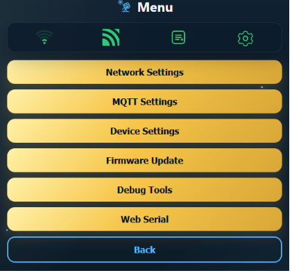
Network & MQTT Settings: 이더넷 고정 IP 설정 및 MQTT 브로커 연동.
Firmware Update: 웹에서 직접 최신 펌웨어 OTA 업데이트 지원.
Web Serial Debug: USB 연결 없이 웹 브라우저에서 실시간 시리얼 로그 확인 가능.
7. Real-time Results
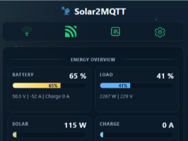
유선 이더넷을 통해 수집된 데이터는 지연 없이 대시보드에 반영됩니다.
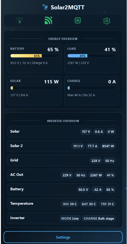
대시보드를 통해 배터리 잔량(65%), 현재 부하량(2267W), 태양광 발전량(115W) 등을 확인할 수 있으며, 인버터 내부 온도(INV 39°C)와 배터리 전압(50.5V) 등 미세한 변화까지 놓치지 않고 기록합니다.
8. Practical Tips / Pitfalls
- RS485와 W5500 SPI 라인을 명확히 분리해야 핀 충돌을 방지할 수 있습니다.
- 산업 환경에서는 DHCP보다 Static IP 설정이 유지보수에 유리합니다.
- Ethernet 초기화 실패 시 Wi-Fi fallback 동작을 확인해야 합니다.
- W5500은 3.3V 로직이므로 전압 레벨을 반드시 맞춰야 합니다.
- RS485 DE/RE 제어(GPIO15)는 통신 안정성에 직접적인 영향을 줍니다.
- Ethernet이 안정적이어도 인버터 프로토콜 오류는 별도로 디버깅해야 합니다.
9. FAQ
Q: 왜 W5500을 사용하나요?
A: Wi-Fi 대신 유선 이더넷을 사용하여 RF 간섭, 거리, 벽 등의 영향 없이 안정적인 데이터 전송을 확보할 수 있습니다. 또한 하드웨어 TCP/IP 오프로딩으로 ESP32의 CPU 부담을 줄입니다.
Q: ESP32-S3에 어떻게 연결되나요?
A: SPI 인터페이스로 연결되며 MISO(12), MOSI(11), SCLK(13), CS(14), RST(9), INT(10) 핀을 사용합니다. ETH.begin() 함수로 초기화됩니다.
Q: 이 프로젝트에서 W5500은 어떤 역할을 하나요?
A: 인버터에서 수집된 데이터를 MQTT, 웹 UI, JSON API로 전달하는 네트워크 전송 계층 역할을 합니다.
Q: 초보자도 따라할 수 있나요?
A: ESP32 개발 경험과 UART/RS485, MQTT 기본 이해가 필요합니다. 하지만 W5500이 내장된 보드를 사용하면 하드웨어 난이도는 크게 낮아집니다.
Q: Wi-Fi와 비교하면 어떤 차이가 있나요?
A: Wi-Fi는 설치가 간편하지만 환경에 따라 끊김이 발생할 수 있습니다. W5500 기반 Ethernet은 물리적으로 연결된 만큼 지연과 패킷 손실이 훨씬 안정적입니다.
Summary
Solar power systems are often installed in harsh network environments such as outdoor locations or electrical rooms. Traditional Wi-Fi setups are prone to data loss or disconnections due to walls, distance, or interference.
This project demonstrates how to build a Solar2MQTT system using the Waveshare ESP32-S3-ETH board with the WIZnet W5500 Ethernet controller, enabling uninterrupted 24/7 data transmission. It collects real-time data from a solar inverter and delivers it to Home Assistant via MQTT.
What the Project Does
The project acts as a gateway between a solar inverter and the network.
On the device side, it reads data from the inverter via RS485 (or RS232). On the network side, it transmits data via MQTT and provides a web UI for monitoring and configuration.
Key features include:
- Real-time data transmission via MQTT
- Web UI for configuration and status monitoring
/livejsonendpoint for structured data access- Web-based OTA firmware updates
- USB and WebSerial debugging support
On the Waveshare ESP32-S3-ETH board, inverter communication uses GPIO17 (RX), GPIO18 (TX), and GPIO15 (DE/RE), while the W5500 is connected through dedicated SPI pins.
Where WIZnet Fits
This project uses the WIZnet W5500.
The W5500 is an Ethernet controller connected to the ESP32-S3 via SPI, and it serves as the wired network transport layer in this system. Inverter data is collected through UART/RS485, and then transmitted through the W5500 to MQTT brokers, web interfaces, and OTA services.
The architecture is clearly separated:
- UART: inverter communication (data acquisition)
- W5500: network transport (data delivery)
- RS485 to TTL module: Modbus communication interface
Solar installations are often deployed in electrical rooms, outdoor enclosures, or metal cabinets where Wi-Fi reliability is poor. In these cases, W5500-based wired Ethernet ensures stable, uninterrupted data transmission.
Additionally, the W5500 uses hardware TCP/IP offloading, allowing the ESP32-S3 to focus on inverter processing and application logic without handling the full network stack.
Pin Mapping
The following pin definitions are fixed for the onboard W5500 and inverter communication:
| Function | ESP32-S3 GPIO | Notes |
|---|---|---|
| W5500 MISO / MOSI | GPIO 12 / 11 | SPI communication |
| W5500 SCLK / CS | GPIO 13 / 14 | SPI clock and chip select |
| W5500 RST / INT | GPIO 9 / 10 | Reset and interrupt |
| Inverter RX / TX | GPIO 17 / 18 | RS485 data communication |
| RS485 DE / RE | GPIO 15 | Flow control |
Implementation Notes
Solar2MQTT includes a dedicated build target for W5500.
File: platformio.ini
[env:waveshare_esp32_s3_eth]
build_flags =
  -DHAS_LAN=1
  -DETH_SPI_W5500=1
  -DPIN_ETH_SPI_MISO=12
  -DPIN_ETH_SPI_MOSI=11
  -DPIN_ETH_SPI_SCLK=13
  -DPIN_ETH_SPI_CS=14
  -DPIN_ETH_SPI_RST=9
  -DPIN_ETH_SPI_INT=10
This configuration defines the SPI pin mapping for the W5500.
It shows that Ethernet support is not generic, but explicitly designed around the W5500 hardware.
File: src/core/WiFiManager.cpp
#if defined(ETH_SPI_W5500) && ETH_SPI_W5500
  const bool ok = ETH.begin(ETH_PHY_W5500,
                            ETH_PHY_ADDR_AUTO,
                            PIN_ETH_SPI_CS,
                            PIN_ETH_SPI_INT,
                            PIN_ETH_SPI_RST,
                            SPI2_HOST,
                            PIN_ETH_SPI_SCLK,
                            PIN_ETH_SPI_MISO,
                            PIN_ETH_SPI_MOSI);
#endif
This code initializes the W5500-based Ethernet interface.
Key points:
ETH_PHY_W5500explicitly selects the W5500- SPI pins are passed directly → fixed board-level configuration
- Supports both DHCP and static IP configuration
This confirms that W5500 is not optional—it is the actual network execution path.
Web UI (Features)
Solar2MQTT provides an intuitive web interface. Thanks to the fast response of wired Ethernet via the W5500, configuration changes and log monitoring are smooth and responsive.
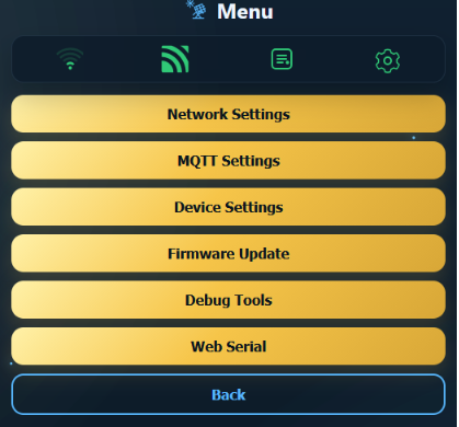
- Network & MQTT Settings: Configure static IP and connect to MQTT broker
- Firmware Update: Perform OTA updates directly from the browser
- Web Serial Debug: View real-time serial logs without USB connection
Real-time Results
Data collected via wired Ethernet is reflected on the dashboard without delay.
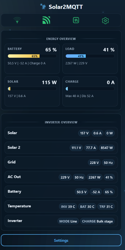
The dashboard displays detailed metrics such as:
- Battery level (65%)
- Current load (2267W)
- Solar generation (115W)
- Inverter temperature (39°C)
- Battery voltage (50.5V)
This enables precise monitoring of even small fluctuations in system performance.
Practical Tips / Pitfalls
- Separate RS485 and W5500 SPI lines to avoid pin conflicts
- Use static IP in industrial environments for easier maintenance
- Verify Wi-Fi fallback behavior if Ethernet initialization fails
- Ensure proper 3.3V logic level compatibility for W5500
- RS485 DE/RE control (GPIO15) directly affects communication stability
- Stable Ethernet does not eliminate inverter protocol issues—debug separately
FAQ
Q: Why use W5500?
A: It provides stable wired Ethernet communication without RF interference, distance, or obstruction issues. It also reduces CPU load through hardware TCP/IP offloading.
Q: How is it connected to ESP32-S3?
A: It uses SPI with MISO(12), MOSI(11), SCLK(13), CS(14), RST(9), and INT(10). Initialization is done via ETH.begin().
Q: What role does W5500 play in this project?
A: It acts as the network transport layer, delivering inverter data to MQTT, web UI, and APIs.
Q: Can beginners follow this project?
A: Basic knowledge of ESP32, UART/RS485, and MQTT is required. Using a board with built-in W5500 significantly reduces hardware complexity.
Q: How does it compare to Wi-Fi?
A: Wi-Fi is easier to deploy but less reliable in harsh environments. Ethernet via W5500 provides stable latency and minimal packet loss.