
Implementing High-Speed Ethernet Communication with WIZnet W5300 and FPGA
A practical guide to interfacing the WIZnet W5300 with FPGA for real-time embedded network systems using a 16-bit parallel bus.
WIZnet - W5300
x 1
Meta Description
Learn how to design high-speed TCP/IP network systems by integrating the WIZnet W5300 Ethernet controller with an FPGA. This post covers PoE-based power design, hardware architecture, and real-world application in an electronic warfare system.
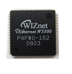
What is the WIZnet W5300?
The WIZnet W5300 is a standalone Ethernet controller with a built-in TCP/IP hardware stack. It supports 8 independent sockets and is suitable for microcontroller or FPGA-based systems via a 16-bit parallel bus.
Supported Protocols: TCP, UDP, IP, ARP, ICMP
Interface: Parallel data bus with CS, RD, WR, and RESET control signals
Power over Ethernet (PoE) support with external circuitry
System Architecture: W5300 + FPGA Integration Overview
The system described here is based on a real-world design used in an RF signal processing system developed at a Russian technical university (SUT).
Key Components
| Component | Description |
|---|---|
| FPGA (Spartan-6) | Main control and signal processing logic |
| W5300 (WIZnet) | Handles Ethernet communication via TCP/IP |
| ARM7 LPC2458 | Auxiliary control and management |
| LMS6002D | RF transceiver for I/Q signal input/output |
| PoE Module | Power via Ethernet (IEEE 802.3af) |
| SDRAM/Flash | Stores FPGA bitstreams and firmware |
📷 Ethernet ↔ W5300 ↔ FPGA ↔ Transceiver ↔ RF Signals
W5300-to-FPGA Interface Design
Data Bus: 16-bit wide (D[15:0])
Address Decoding: A[3:0] used for internal register access
Control Signals: Chip Select (CS), Read (RD), Write (WR), Reset (RESET)
Interrupt (INTn): Optional, used to indicate receive events
💡 Tip: FSM-based bus controllers are recommended to manage WR/RD timing and bus hold intervals.
Use Case: Electronic Warfare System
The W5300 is optimized for high-throughput, real-time data transmission, making it suitable for use in tactical embedded systems.
Real-Time Scenarios
Signal Acquisition: FPGA receives I/Q samples from LMS6002D and transmits via Ethernet
Signal Transmission: Predefined RF patterns are sent through W5300 to a remote server
Status Feedback: FPGA controls LEDs and logs system status via UART console
Hardware Design Considerations
Reset Timing: Apply reset after power stabilization (LOW → HIGH sequence)
Clock Domain Crossing: Insert synchronizers if FPGA and W5300 clocks differ
PoE Safety: Add ESD and surge protection circuits for 802.3af compliance
Conclusion & Design Summary
The W5300 enables hardware-accelerated TCP/IP offloading, significantly reducing resource usage on the FPGA while maintaining stable communication performance.
Recommended Design Strategies
Use a dedicated FSM for register access timing
Map W5300 control/status registers carefully in your FPGA logic
Design board layout to accommodate PoE and ESD protection
Keywords for SEO
WIZnet W5300, W5300 FPGA, Ethernet hardware stack, FPGA Ethernet controller, TCP/IP offloading, parallel bus interface, PoE embedded design, RF data streaming, Spartan-6 Ethernet, W5300 Verilog example