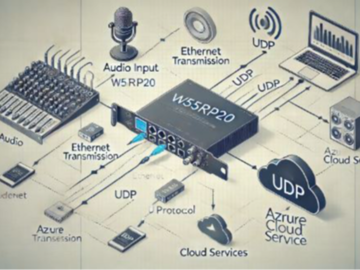
How to send voice data via ethernet
Using the W55RP20, audio data is transmitted via UDP, then processed using Azure's cloud services.
If audio data is transmitted over Ethernet....

Base Project
https://github.com/WIZnet-ioNIC/WIZnet-PICO-AZURE-C
adc_fifo_setup(
true,    // Write each completed conversion to the sample FIFO
true,    // Enable DMA data request (DREQ)
1,       // DREQ (and IRQ) asserted when at least 1 sample present
true,   // We won't see the ERR bit because of 8 bit reads; disable.
false // Shift each sample to 8 bits when pushing to FIFO
);
adc_set_clkdiv(ADC_CLK_VAL);//2999= 16kS/sThis explanation describes the process of setting up the sampling rate for an ADC (Analog-to-Digital Converter).
Base Clock:
The ADC clock (ADC CLK) is set to 48 MHz.Divider:
To reduce the ADC sampling rate, a divider is used. The divider takes the input clock and divides it by a specified value to determine the actual sampling rate of the ADC.Divider Calculation:
The divider is set to 1 + 2999, where 2999 is the user-defined value. Therefore, the divider is calculated as follows:
Sampling Rate Calculation:
The ADC sampling rate is determined by dividing the input clock by the divider.
Through this calculation, the ADC is configured to sample at a rate of 16,000 samples per second (16 kS/s).
In summary, by dividing the 48 MHz clock by 3000, a sampling rate of 16 kS/s is achieved. This sampling rate is chosen based on the required resolution for digitizing the signal.


