



BMS-Fake-WiFi(Smart Battery Management System)
Arduino Mega 2560 firmware for a 4-cell Li-ion BMS by @QDarkRex, with per-cell protection and a W5500 Ethernet web dashboard + REST API. (from Indonesia)
프로젝트가 하는 일
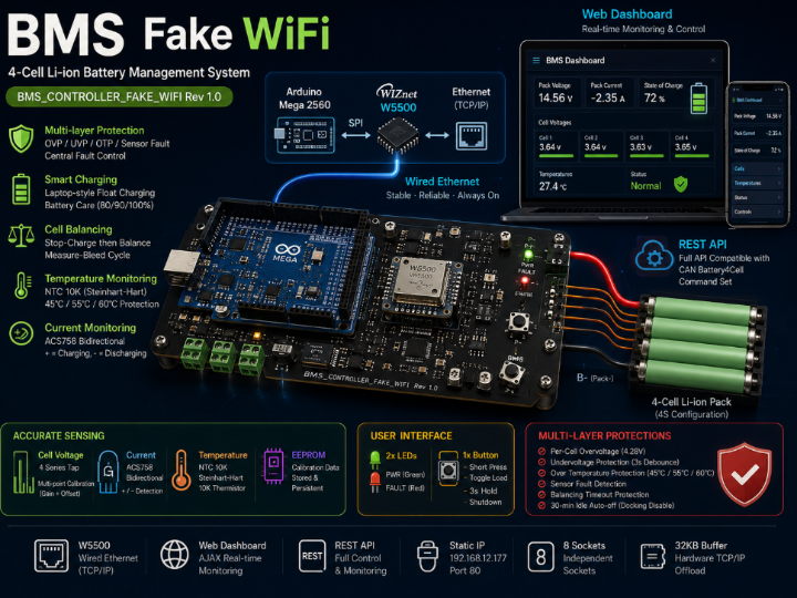
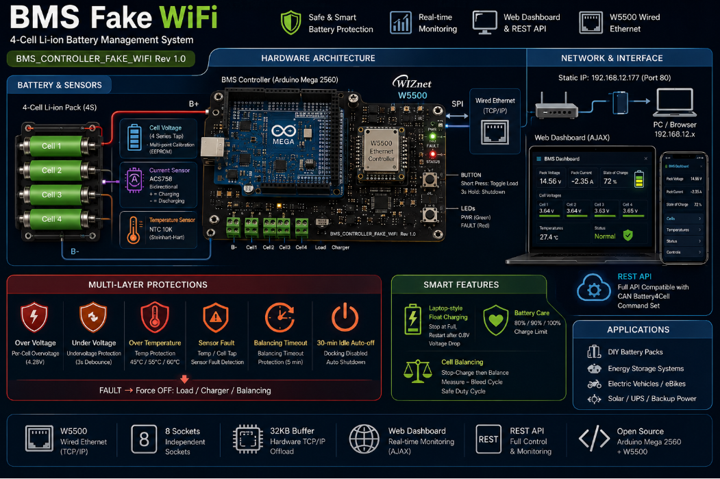
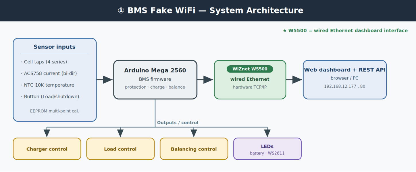
BMS Fake WiFi는 Arduino Mega 2560(ATmega2560) 펌웨어로 구현한 4직렬(4S) LiPo 배터리 관리 시스템(BMS) 입니다. 보드는 BMS_CONTROLLER_FAKE_WIFI Rev 1.0이며, W5500 유선 Ethernet 기반의 웹 대시보드 + REST API로 배터리 상태를 실시간 모니터링·제어합니다.
기본 배터리 파라미터: 만충 4.125V/셀(팩 16.5V), 방전 하한 3.05V/셀, 셀 과전압 보호 트립 4.28V.
- 셀별 전압: 4직렬 누적 탭(A0–A3, LM358 op-amp 경유) → 셀별 차분 계산 + EEPROM에 저장되는 다점 보정(gain+offset, 최소자승)
- SOC: LiPo OCV 룩업 + 보간, EMA 평활 (
vmin=0%,vmax/4=100%로 스케일) - 전류: ACS758-100B(+MAX4213) 양방향 (+충전/−방전)
- 온도: NTC 10K 서미스터(Steinhart-Hart), 펌웨어에
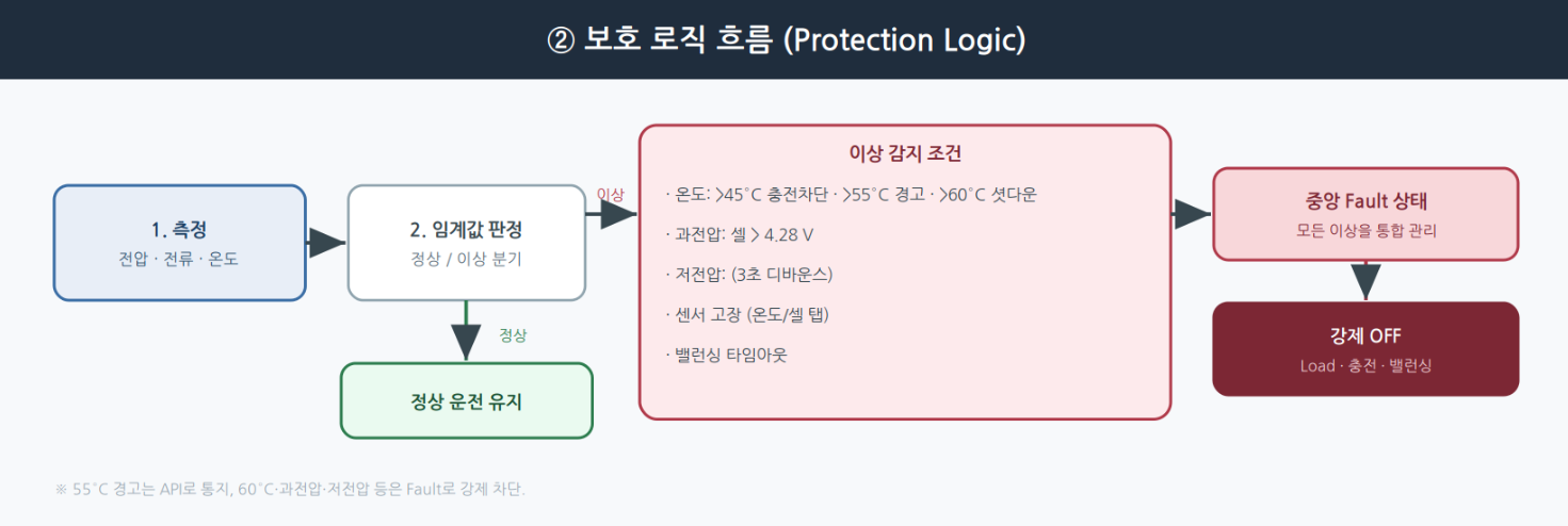
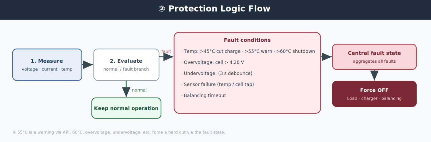
TEMP_OFFSET=4.0°C보정 - 다단계 온도 보호: 45°C↑ 충전 차단 · 55°C↑ 경고(API) · 60°C↑ 셧다운(3초 디바운스)
- 셀 과전압(4.28V) / 저전압(기본 3.05V) 보호
- 중앙 Fault 상태(bitmask):
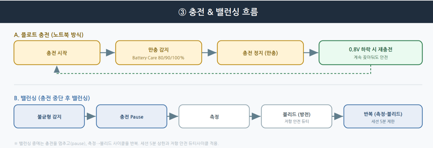
temp_sensor·overheat_critical·cell_sensor·cell_overvoltage·cell_undervoltage·manual_balance_timeout→ 하나라도 활성 시 Load/충전/밸런싱 강제 OFF, LED 적청 스트로브, API는output_blocked_fault반환 - 노트북식 플로트 충전: 만충 정지, 0.8V 하락 후 재충전 + Battery Care(longevity 16.0V ≈80% / balanced 16.4V ≈90% / full 16.5V =100%)
- 밸런싱(패시브, 충전 중단 후): 충전 PAUSE → 측정(1.5s)/블리드(2s) 반복 → 셀 편차 <8mV 도달 시 충전 재개, 세션 5분 상한, 블리드 저항 39Ω 2512 1W
- LED/버튼: 배터리 RGB LED + WS2811 상태 LED, 버튼 짧게=Load 토글 / 3초=종료(웨이크 가드)
- 웹 대시보드(AJAX) + REST API: CAN Battery4Cell 명령셋을 반영
WIZnet이 들어가는 위치
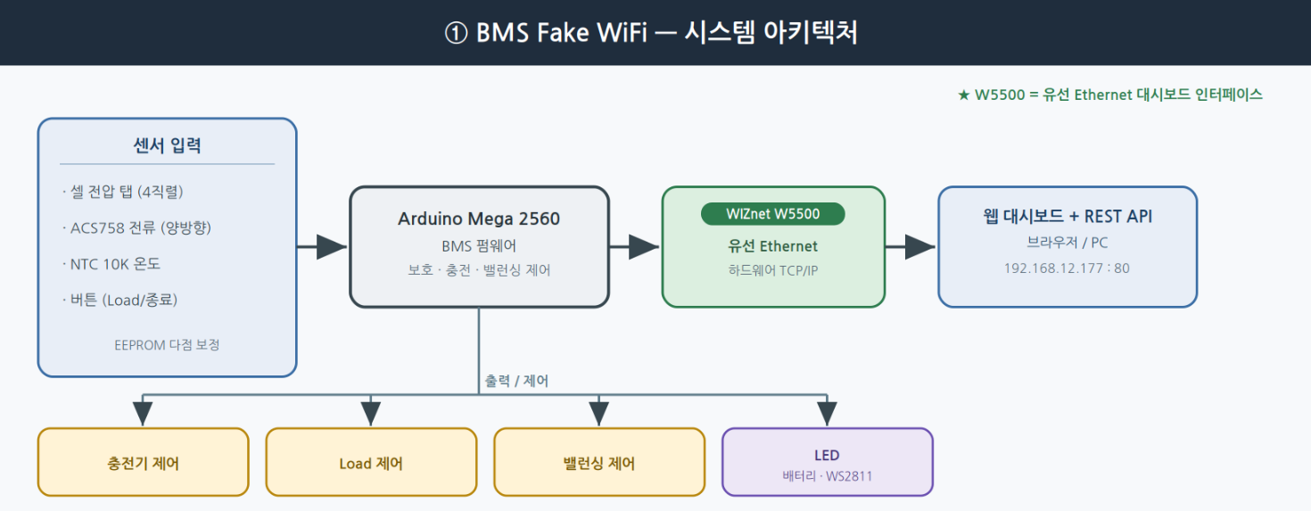
이 프로젝트에서 사용되는 WIZnet 제품은 W5500이며, Arduino Mega 2560에 유선 Ethernet 인터페이스(SPI, CS=D53 / RST=D4)를 제공합니다. BMS 상태(셀 전압·전류·온도·SOC·Fault)를 웹 대시보드와 REST API로 실시간 모니터링·제어하는 통로입니다. W5500은 하드웨어 TCP/IP 스택·SPI·8소켓·32KB 버퍼를 제공하므로, MCU가 배터리 보호/제어 로직에 집중하는 동안 안정적인 유선 네트워크를 담당합니다. 기본 정적 IP 192.168.12.177(포트 80), PC는 192.168.12.x 서브넷. CORS 개방(*), 모든 엔드포인트 GET, 웹서버는 단일 스레드.
핀맵 (firmware ↔ hardware)
| 기능 | 핀 | 비고 |
|---|---|---|
| 전원 래치 | D2 | HIGH=유지, LOW=완전 종료 |
| W5500 RST / CS | D4 / D53 | SPI 버스 |
| Load FET | D27 | beban 출력 |
| 충전 리턴 FET | D28 | charge− 경로 |
| 충전기+ P-FET (Q21) | D10 | charger+ 게이트 |
| 버튼(opto) | A8 | analogRead > 1000 |
| 서미스터 | A6 | NTC 10K (TEMP_1) |
| 셀 탭 (총·3·2·1) | A3 / A1 / A2 / A0 | LM358 op-amp 경유(누적) |
| 전류 센서 | A4 | ACS758-100B + MAX4213 |
| 밸런싱 FET 1..4 | D3 / D5 / D7 / D9 | 셀별 블리드 |
| 배터리 RGB LED | D25 / D23 / D24 | 용량/충전/위험 |
| WS2811 상태 LED | D22 | addressable |
REST API (요약)
Base URL http://192.168.12.177 · 모두 GET · JSON 응답(대시보드 계열은 204).
센서/상태 읽기: GET /api/all(한 번에 스냅샷) · /api/cells · /api/cell?n=1 · /api/current · /api/temperature · /api/capacity · /api/status · /api/faults · /api/v2/telemetry(구조화 envelope). 상태코드 0=Idle,1=Charging,2=Balancing,3=Load.
제어: GET /api/control?cmd=charge_on|charge_off|load_on|load_off|balance_on|balance_off|shutdown (Fault lockout 시 charge_on/load_on/balance_on은 output_blocked_fault로 거부, 수동 밸런싱은 5분 하드 타임아웃).
설정/보정: /api/set_vmax?value=16.5 · /api/set_vmin?value=3.05 · /api/battery_care?mode=longevity|balanced|full · /api/set_time?epoch=&tz= · /api/cal_add → /api/cal_compute(다점 보정) · /api/cal_get|cal_status|cal_reset|cal_debug · /api/eeprom_reset.
LED: POST /api/v1/led (body {"app":true,"state":"idle|scanning|attacking","alfa":3}) · GET /api/v1/led. LED 상태는 관련 프로젝트에서 온 표시용 라벨이며 BMS 동작과는 무관.
폴링 권장:
GET /api/all하나로 1초 간격, 요청 중첩 금지(클라이언트 타임아웃 ~2초). 전체 목록은 저장소API_COMMANDS.md참고.
구현 메모
- 빌드: Arduino IDE에서
main/폴더를 열고 보드를 Arduino Mega 2560으로 선택 후 Upload. 필요한 라이브러리는 Ethernet, Adafruit_NeoPixel. - 네트워크: 정적 IP
192.168.12.177(포트 80). 대시보드는main/eth.ino의 웹 서버가 제공. - 파일 구조:
| 파일 | 내용 |
|---|---|
main/main.ino | Setup·loop·핀·전역변수·EEPROM |
main/percell_voltage.ino | 셀 전압 읽기 + 밸런싱 로직 + 보정 |
main/current.ino | ACS758 전류 센서 읽기 |
main/temp.ino | 온도 읽기 + 온도 기반 충전 보호 |
main/control.ino | 버튼·자동 종료·배터리 LED·WS2811 상태 LED |
main/eth.ino | 웹 서버·대시보드 HTML·REST API |
API 엔드포인트 전체 목록은 저장소의
API_COMMANDS.md, 배선/보정/이슈 등은HANDOVER.md를 참고하세요.
⚠️ 안전 주의 (리튬 배터리)
리튬이온 배터리는 과충전·과방전·과열·단락 시 발화·폭발 위험이 있습니다. 이 프로젝트가 다단계 보호를 제공하더라도, 실제 구성·시험 시에는 셀 사양 준수, 적절한 퓨즈/보호회로, 온도 감시, 관리·감독이 필수입니다. 이 글은 프로젝트 소개용이며 안전 설계·인증을 대체하지 않습니다.
유사 프로젝트
두 프로젝트는 모두 W5500 유선 Ethernet으로 센서 데이터를 수집·모니터링하는 시스템이라는 점에서 유사합니다. 다만 BMS Fake WiFi는 배터리 보호·충전·밸런싱까지 제어하는 배터리 관리 시스템이고, ssekim의 글은 산업 모니터링용 범용 센서 시스템의 Ethernet 서브시스템 설명에 가깝습니다.
| 항목 | BMS Fake WiFi | Simple Sensor System (Industrial) |
|---|---|---|
| 목적 | 배터리 관리·보호·제어 | 산업 센서 모니터링 |
| 대상 | 4셀 Li-ion 팩 | 범용 센서 |
| MCU | Arduino Mega 2560 | (Ethernet 서브시스템 중심) |
| 제어 | 충전/밸런싱/보호 능동 제어 | 주로 데이터 수집 |
| 인터페이스 | 웹 대시보드 + REST API | Ethernet 데이터 경로 |
| W5500 역할 | 유선 모니터링/제어 인터페이스 | 유선 데이터 인터페이스 |
FAQ
Q: 이름이 "Fake WiFi"인데 공격 도구인가요? A: 아니요. 로그 AP나 이블트윈 같은 공격 기능이 전혀 없습니다. 보드 별명(BMS_CONTROLLER_FAKE_WIFI)에서 온 것으로, 유선 W5500 이더넷으로 무선 대시보드처럼 쓴다는 의미입니다. 실체는 배터리 관리 시스템입니다.
Q: 무엇을 관리하나요? A: 4직렬 리튬이온 셀의 전압/전류/온도를 측정하고, 과전압·저전압·과열 보호와 충전·밸런싱을 수행합니다.
Q: W5500은 어떤 역할인가요? A: Arduino Mega 2560에 유선 이더넷을 부여해, 웹 대시보드와 REST API로 BMS 상태를 실시간 모니터링·제어하는 네트워크 인터페이스입니다.
Q: 어떻게 접속하나요? A: 기본 정적 IP 192.168.12.177(포트 80). PC를 192.168.12.x 서브넷에 두고 브라우저로 접속합니다.
What the Project Does
BMS Fake WiFi is a 4-series (4S) LiPo Battery Management System implemented as Arduino Mega 2560 (ATmega2560) firmware. The board is BMS_CONTROLLER_FAKE_WIFI Rev 1.0, and it monitors/controls the battery through a web dashboard + REST API over W5500 wired Ethernet.
Default battery parameters: full 4.125 V/cell (pack 16.5 V), empty floor 3.05 V/cell, per-cell overvoltage trip 4.28 V.
- Per-cell voltage: cumulative taps (A0–A3 via LM358 op-amps) → per-cell by difference + EEPROM multi-point calibration (gain+offset, least-squares)
- SOC: LiPo OCV lookup + interpolation, EMA smoothing (scaled
vmin=0%,vmax/4=100%) - Current: ACS758-100B (+MAX4213) bidirectional (+ charging / − discharging)
- Temperature: NTC 10K thermistor (Steinhart-Hart), firmware
TEMP_OFFSET=4.0 °C - Tiered thermal protection: >45 °C cut charge · >55 °C warning (API) · >60 °C shutdown (3 s debounce)
- Per-cell overvoltage (4.28 V) / undervoltage (default 3.05 V) protection
- Central fault state (bitmask):
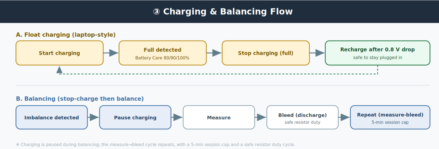
temp_sensor·overheat_critical·cell_sensor·cell_overvoltage·cell_undervoltage·manual_balance_timeout→ any active forces Load/charger/balancing OFF, red-blue LED strobe, API returnsoutput_blocked_fault - Laptop-style float charging: stop at full, recharge only after a 0.8 V drop, plus Battery Care (longevity 16.0 V ≈80% / balanced 16.4 V ≈90% / full 16.5 V =100%)
- Balancing (passive, stop-charge): pause charger → measure(1.5 s)/bleed(2 s) cycles → resume when cell delta <8 mV, 5-min session cap, 39 Ω 2512 1 W bleed resistor
- LEDs/button: battery RGB LED + WS2811 status LED, button short = toggle Load / 3-s hold = shutdown (wake guard)
- Web dashboard (AJAX) + REST API: mirrors the CAN Battery4Cell command set
Where WIZnet Fits
The WIZnet product used is the W5500, giving the Arduino Mega 2560 a wired Ethernet interface (SPI, CS=D53 / RST=D4). It is the path by which BMS state (cell voltages, current, temperature, SOC, faults) is monitored and controlled in real time via a web dashboard and REST API. With its hardware TCP/IP stack, SPI, 8 sockets, and 32 KB buffer, the W5500 handles a stable wired network while the MCU focuses on battery protection/control. Default static IP 192.168.12.177 (port 80), PC on the 192.168.12.x subnet, CORS open (*), all endpoints GET, single-thread web server.
Pin Map (firmware ↔ hardware)
| Function | Pin | Notes |
|---|---|---|
| Power latch | D2 | HIGH=stay on, LOW=full off |
| W5500 RST / CS | D4 / D53 | SPI bus |
| Load FET | D27 | load output |
| Charge return FET | D28 | charge− path |
| Charger+ P-FET (Q21) | D10 | charger+ gate |
| Button (opto) | A8 | analogRead > 1000 |
| Thermistor | A6 | NTC 10K (TEMP_1) |
| Cell taps (total·3·2·1) | A3 / A1 / A2 / A0 | via LM358 op-amps (cumulative) |
| Current sensor | A4 | ACS758-100B + MAX4213 |
| Balancing FET 1..4 | D3 / D5 / D7 / D9 | per-cell bleed |
| Battery RGB LED | D25 / D23 / D24 | capacity/charge/danger |
| WS2811 status LED | D22 | addressable |
REST API (summary)
Base URL http://192.168.12.177 · all GET · JSON responses (dashboard-family returns 204).
Sensor/state reads: GET /api/all (single snapshot) · /api/cells · /api/cell?n=1 · /api/current · /api/temperature · /api/capacity · /api/status · /api/faults · /api/v2/telemetry (structured envelope). Status codes 0=Idle, 1=Charging, 2=Balancing, 3=Load.
Control: GET /api/control?cmd=charge_on|charge_off|load_on|load_off|balance_on|balance_off|shutdown (under fault lockout, charge_on/load_on/balance_on are rejected with output_blocked_fault; manual balancing has a 5-min hard timeout).
Config/calibration: /api/set_vmax?value=16.5 · /api/set_vmin?value=3.05 · /api/battery_care?mode=longevity|balanced|full · /api/set_time?epoch=&tz= · /api/cal_add → /api/cal_compute (multi-point) · /api/cal_get|cal_status|cal_reset|cal_debug · /api/eeprom_reset.
LED: POST /api/v1/led (body {"app":true,"state":"idle|scanning|attacking","alfa":3}) · GET /api/v1/led. These LED states are display-only labels inherited from a related project and are unrelated to BMS operation.
Polling: use a single
GET /api/allat a 1-second interval; do not overlap requests (client timeout ~2 s). Full list in the repo'sAPI_COMMANDS.md.
Implementation Notes
- Build: open the
main/folder in Arduino IDE, select Arduino Mega 2560, then Upload. Required libraries: Ethernet, Adafruit_NeoPixel. - Network: static IP
192.168.12.177(port 80). The dashboard is served by the web server inmain/eth.ino. - File structure:
| File | Contents |
|---|---|
main/main.ino | setup·loop·pins·globals·EEPROM |
main/percell_voltage.ino | cell voltage read + balancing + calibration |
main/current.ino | ACS758 current sensor read |
main/temp.ino | temperature read + charge protection by temp |
main/control.ino | button·auto-shutdown·battery LED·WS2811 status LED |
main/eth.ino | web server·dashboard HTML·REST API |
See
API_COMMANDS.mdfor the full endpoint list andHANDOVER.mdfor wiring/calibration/known issues.
⚠️ Safety Note (Lithium Batteries)
Lithium-ion cells can catch fire or explode if overcharged, over-discharged, overheated, or short-circuited. Even though this project provides multi-layer protection, real builds and tests require adherence to cell specifications, proper fuses/protection circuits, temperature monitoring, and supervision. This write-up is an introduction and does not replace proper safety design and certification.
Similar Project
Both projects are similar in that they collect and monitor sensor data over W5500 wired Ethernet. However, BMS Fake WiFi is a battery management system that also controls protection, charging, and balancing, while ssekim's article is closer to describing the Ethernet subsystem of a general-purpose industrial monitoring sensor system.
| Item | BMS Fake WiFi | Simple Sensor System (Industrial) |
|---|---|---|
| Purpose | Battery management/protection/control | Industrial sensor monitoring |
| Target | 4-cell Li-ion pack | General sensors |
| MCU | Arduino Mega 2560 | (Ethernet-subsystem centric) |
| Control | Active charge/balance/protection | Mostly data collection |
| Interface | Web dashboard + REST API | Ethernet data path |
| W5500 role | Wired monitoring/control interface | Wired data interface |
FAQ
Q: The name says "Fake WiFi" — is it an attack tool? A: No. It has no rogue-AP or evil-twin functionality. The name comes from the board nickname (BMS_CONTROLLER_FAKE_WIFI) — it uses wired W5500 Ethernet as if it were a wireless dashboard. It is a battery management system.
Q: What does it manage? A: It measures voltage/current/temperature of 4 series Li-ion cells and performs overvoltage/undervoltage/overheat protection plus charging and balancing.
Q: What role does the W5500 play? A: It gives the Arduino Mega 2560 wired Ethernet so the BMS state can be monitored/controlled in real time via a web dashboard and REST API.
Q: How do I connect? A: Default static IP 192.168.12.177 (port 80). Put your PC on the 192.168.12.x subnet and open it in a browser.
-
Schematic_FakeWifiBMSControl_2026-06-24.pdf
schematic

-
HANDOVER.md
full handover (hardware, as-built mods, firmware, build, calibration, issues)
-
API_COMMANDS.md
complete REST API endpoint list
-
USER_GUIDE.md
plain-language guide (LEDs, button, charging, safety)
-
DEVELOPMENT_NOTES.md
development journey (decisions & "why")