



Battery-Emulator
An ESP32-S3 fork of Battery-Emulator by @sulfurvinter that repurposes EV packs for home storage, adding web-configurable GPIO, dual CAN-FD, and W5500 Ethernet.
프로젝트가 하는 일
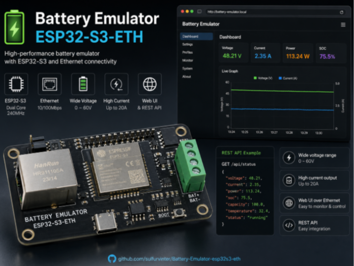
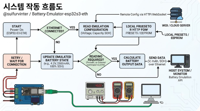
Battery-Emulator는 전기차(EV) 배터리 팩을 가정용 정치형 에너지 저장장치(ESS)로 재사용할 수 있게 해주는 오픈소스 프로젝트입니다. EV 배터리와 가정용 인버터 사이의 번역(translation) 계층으로 동작해, 서로 다른 EV 배터리와 인버터가 CAN 등으로 통신할 수 있도록 프로토콜을 변환합니다. 덕분에 크고 저렴한 EV 배터리를 plug'n'play에 가깝게 가정 저장용으로 쓸 수 있습니다.
이 저장소는 @sulfurvinter가 만든 포크로, 원본(dalathegreat v10.12.0)에 범용 ESP32-S3 보드용 타깃(esp32s3_generic_330) 을 추가한 것이 핵심입니다.
이 포크가 추가한 것:
- 웹으로 설정하는 GPIO: 펌웨어에 핀을 하드코딩하지 않고, 플래시 후 웹 UI(Settings → GPIO Pin Configuration)에서 런타임에 모든 핀을 배정. 설정은 NVS에 저장되어 재부팅 후에도 유지(기본값은 모두 -1=미연결).
- 듀얼 CAN-FD: MCP2517FD/MCP2518FD CAN-FD 애드온 2개 + 내장 TWAI/MCP2515까지 지원.
- W5500 Ethernet: SPI 기반 유선 이더넷을 옵션으로 추가.
지원 인터페이스(웹에서 핀 배정): CAN Native(TWAI), RS485, MCP2515(SPI), MCP2517FD/2518FD CAN-FD ×2(SPI), W5500 Ethernet(SPI), 양·음 접점기, 프리차지 릴레이, BMS 전원 제어, NeoPixel LED, SSD1306 OLED(I2C).
COMPONENTS
| Component | Notes | Qty |
|---|---|---|
| ESP32-S3 generic dev board (16MB flash) | 펌웨어 실행 MCU (esp32s3_generic_330) | x 1 |
| WIZnet W5500 Ethernet module (SPI) | 유선 Ethernet (WiFi AP는 fallback 유지) | x 1 |
| CAN-FD 트랜시버 (MCP2517FD/2518FD) · MCP2515 · 내장 TWAI | 배터리/인버터 CAN 통신 | x 1~2 |
| RS485 트랜시버 (선택) | 일부 인버터/BMS 통신 | x 1 |
| 접점기(contactor)·프리차지 릴레이 | 고전압 연결 제어 | x N |
| SSD1306 OLED (I2C, 선택) · NeoPixel LED | 상태 표시 | x 1 |
| EV 배터리 팩 + 홈 인버터 (외부) | 재사용 대상 / 연동 대상 | x 1 |
WIZnet이 들어가는 위치
이 포크에서 사용되는 WIZnet 제품은 W5500이며, Battery-Emulator에 유선 Ethernet 연결을 더합니다. Settings → W5500 Ethernet에서 활성화하고 SPI 핀(SCK, MOSI, MISO, CS, INT, RST, SPI bus)을 배정합니다. WiFi AP는 fallback으로 항상 유지됩니다.
핵심 설계 포인트:
- CAN 칩과 다른 SPI 버스 사용 필수: CAN 칩은 ISR 레벨에서 SPI를 쓰므로 버스 경합을 피해야 합니다. 권장 구성은 W5500 = SPI3/HSPI, CAN 칩 = SPI2/FSPI.
- 가정용 ESS처럼 항상 켜져 있어야 하는 정치형 장치에서는 WiFi보다 유선이 안정적입니다. W5500은 하드웨어 TCP/IP 스택·SPI·8소켓·32KB 버퍼로 안정적인 유선 네트워크(웹 UI 모니터링·OTA 등)를 제공하고, ESP32-S3는 배터리/인버터 통신 로직에 집중할 수 있습니다.
- 네트워크 설정이 꼬였을 때는 전원 인가 시 BOOT 버튼 5초 유지로 기본 WiFi AP 모드로 초기화할 수 있습니다.
구현 메모
- 빌드: PlatformIO 환경
esp32s3_generic_330(16MB flash, USB CDC).platformio run -e esp32s3_generic_330. 첫 플래시는firmware.factory.bin, OTA는firmware.bin. - 첫 접속: WiFi AP
BatteryEmulator(비밀번호123456789) →http://192.168.4.1→ GPIO 배정 → 배터리·인버터 종류 선택. - 시리얼: USB CDC
/dev/ttyACM0115200 (별도 UART 어댑터 불필요). - OTA: ElegantOTA — 브라우저
/update또는espota.py. - 의존 라이브러리: Adafruit_NeoPixel, ElegantOTA, ArduinoJson, eModbus, AsyncTCP, ESPAsyncWebServer, acan-esp32, acan2517FD.
다이어그램
아래 세 그림으로 전체 구성·설정·네트워크 구조를 한눈에 볼 수 있습니다. (업로드 시 각 PNG 파일을 첨부하세요.)
① 시스템 아키텍처 —
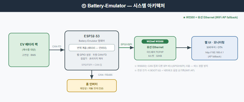
EV 배터리 팩에서 나온 데이터가 CAN-FD로 ESP32-S3(번역 계층) 에 들어오고, ESP32-S3는 한쪽으로는 CAN/RS485로 홈 인버터와 통신하고, 다른 쪽으로는 SPI3/HSPI로 W5500을 구동해 웹 UI·모니터링·OTA 네트워크를 제공합니다. W5500은 유선 이더넷을 담당하고 WiFi AP는 fallback으로 유지되며, CAN 칩은 별도 SPI 버스(SPI2/FSPI)를 씁니다. 즉 "배터리 ↔ 인버터 변환"과 "유선 네트워크 관측"이 한 보드에서 분리된 경로로 동작함을 보여줍니다.
② 웹 GPIO 설정 흐름
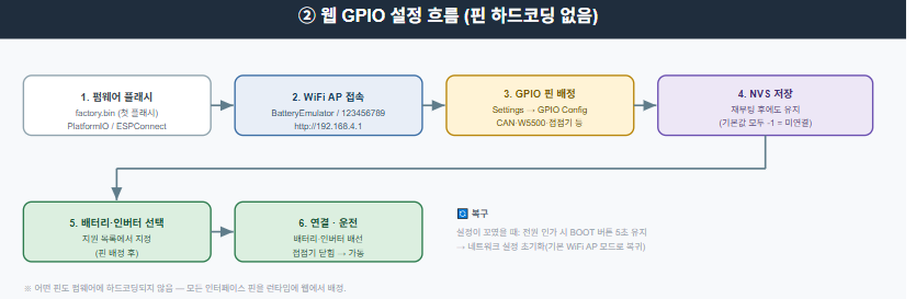
펌웨어 플래시 → WiFi AP 접속(192.168.4.1) → 웹에서 GPIO 핀 배정(CAN·W5500·접점기 등) → NVS 저장(재부팅 유지) → 배터리·인버터 종류 선택 → 연결·운전으로 이어지는 순서입니다. 핵심은 어떤 핀도 펌웨어에 하드코딩되지 않고 런타임에 웹에서 지정된다는 점이며, 설정이 꼬였을 때는 전원 인가 시 BOOT 버튼 5초로 기본 WiFi AP 모드로 복구할 수 있음을 함께 표시합니다.
③ 네트워크 & SPI 버스 분리 구성 —
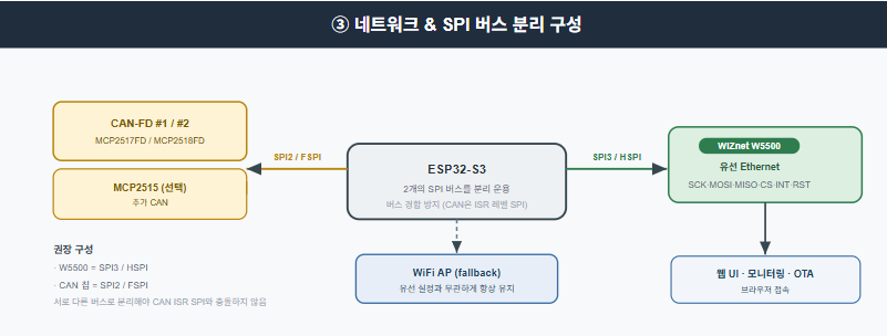
ESP32-S3가 두 개의 SPI 버스를 분리 운용하는 이유를 보여줍니다. CAN 칩은 ISR 레벨에서 SPI를 쓰기 때문에, CAN 칩 = SPI2/FSPI, W5500 = SPI3/HSPI 로 나눠 버스 경합을 피합니다. W5500은 유선 이더넷으로 웹 UI·모니터링·OTA를 제공하고, WiFi AP는 유선 설정과 무관하게 항상 fallback으로 유지됩니다.
⚠️ 안전 주의 (고전압 · 프로토타입)
이 프로젝트는 고전압 EV 배터리와 계통 연계 인버터를 다룹니다. 고전압 작업은 감전·화재·사망 위험이 있으며, 반드시 해당 국가의 법규를 따르고 확신이 없으면 면허 전기기술자와 상담해야 합니다. 또한 이 포크의 펌웨어는 원작자가 "프로토타입 · AI 보조 작성 · 미검증 · 무보증 · 안전critical/양산 부적합" 이라고 명시했습니다. 소개용 글이며 안전 설계·인증을 대체하지 않습니다.
유사 프로젝트
https://maker.wiznet.io/gunn/projects/esp32-s3-ethernet-w5500-modbus-tcp-connect-to-modbus-poll/
두 프로젝트는 모두 ESP32-S3 + W5500으로 Modbus를 이더넷으로 주고받고, 전압·전류·온도 데이터를 다룬다는 점에서 유사합니다. gunn의 프로젝트는 ESP32-S3 + W5500으로 Modbus TCP 통신을 구현해 전압·전류·온도·알람 데이터를 Modbus 주소에 매핑해 전송하는(Modbus Poll 연동, 산업 자동화·SCADA 지향) 예제입니다. 다만 Battery-Emulator는 EV 배터리↔인버터 번역 계층(ESS) 으로 듀얼 CAN-FD·웹 GPIO 설정·웹 UI/OTA까지 포함하는 완결형 애플리케이션이라는 점이 다릅니다.
| 항목 | Battery-Emulator (fork) | ESP32-S3 W5500 Modbus TCP (gunn) |
|---|---|---|
| 목적 | EV 배터리 재사용(ESS) | Modbus TCP 데이터 전송 예제 |
| MCU | ESP32-S3 | ESP32-S3 |
| 네트워크 | W5500 유선(+WiFi fallback) | W5500 유선 |
| 주 통신 | CAN-FD/RS485/Modbus | Modbus TCP |
| 데이터 | 셀 전압·전류·온도·Fault | 전압·전류·온도·알람 |
| 범위 | 배터리·인버터 제어 + 웹 UI | 산업 자동화/SCADA 연동 |
FAQ
Q: 이 프로젝트는 무엇인가요? A: EV 배터리 팩을 가정용 에너지 저장장치로 재사용하도록 EV 배터리와 인버터 사이를 번역하는 오픈소스 펌웨어이며, 이 저장소는 범용 ESP32-S3 + W5500 이더넷을 지원하는 포크입니다.
Q: W5500은 어떻게 쓰이나요? A: 유선 Ethernet 연결(웹 UI·모니터링·OTA)을 제공합니다. 웹에서 SPI 핀을 배정하며, CAN 칩과는 다른 SPI 버스(권장 SPI3/HSPI)를 씁니다. WiFi AP는 fallback으로 유지됩니다.
Q: 왜 유선 이더넷인가요? A: 가정용 ESS처럼 항상 켜져 있어야 하는 장치에서 WiFi보다 안정적이기 때문입니다. W5500의 하드웨어 TCP/IP가 안정성을 높입니다.
Q: 바로 실사용해도 되나요? A: 아니요. 원작자가 프로토타입·AI 보조·미인증 코드임을 명시했고, 고전압 위험이 큽니다. 반드시 안전 규정을 따르고 전문가 상담을 권장합니다.
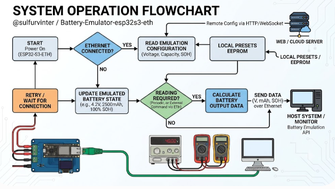
What the Project Does
Battery-Emulator is an open-source project that lets you repurpose electric-vehicle (EV) battery packs as stationary home energy storage (ESS). It acts as a translation layer between an EV battery and a home inverter, converting protocols (over CAN, etc.) so mismatched EV batteries and inverters can talk to each other — making large, cheap EV batteries usable for home storage in a near plug'n'play way.
This repository is a fork by @sulfurvinter that adds a generic ESP32-S3 target (esp32s3_generic_330) to the upstream (dalathegreat v10.12.0).
What the fork adds:
- Web-configurable GPIO: nothing is hardcoded; after flashing, all pins are assigned at runtime via the web UI (Settings → GPIO Pin Configuration). Settings persist in NVS (defaults all -1 = not connected).
- Dual CAN-FD: two MCP2517FD/MCP2518FD CAN-FD add-ons, plus native TWAI / MCP2515.
- W5500 Ethernet: optional SPI-based wired Ethernet.
Configurable interfaces (pins assigned via web): CAN Native (TWAI), RS485, MCP2515 (SPI), MCP2517FD/2518FD CAN-FD ×2 (SPI), W5500 Ethernet (SPI), positive/negative contactors, precharge relay, BMS power control, NeoPixel LED, SSD1306 OLED (I2C).
Where WIZnet Fits
The WIZnet product used in this fork is the W5500, adding wired Ethernet to the Battery-Emulator. Enable it under Settings → W5500 Ethernet and assign SPI pins (SCK, MOSI, MISO, CS, INT, RST, SPI bus). The WiFi AP stays active as a fallback.
Key design points:
- Must use a different SPI bus from the CAN chips: CAN chips use ISR-level SPI, so bus contention must be avoided. Recommended: W5500 on SPI3/HSPI, CAN chips on SPI2/FSPI.
- For an always-on stationary device like a home ESS, wired is more reliable than WiFi. The W5500's hardware TCP/IP stack, SPI, 8 sockets, and 32 KB buffer provide a stable wired network (web-UI monitoring, OTA), letting the ESP32-S3 focus on battery/inverter logic.
- If network settings get misconfigured, hold BOOT for 5 seconds at power-on to reset to the default WiFi AP mode.
Implementation Notes
- Build: PlatformIO env
esp32s3_generic_330(16 MB flash, USB CDC).platformio run -e esp32s3_generic_330. First flash usesfirmware.factory.bin; OTA usesfirmware.bin. - First connect: WiFi AP
BatteryEmulator(password123456789) →http://192.168.4.1→ assign GPIO → pick battery & inverter type. - Serial: USB CDC
/dev/ttyACM0at 115200 (no separate UART adapter). - OTA: ElegantOTA — browser
/updateorespota.py. - Dependencies: Adafruit_NeoPixel, ElegantOTA, ArduinoJson, eModbus, AsyncTCP, ESPAsyncWebServer, acan-esp32, acan2517FD.
Diagrams
These three figures summarize the overall structure, configuration, and network layout. (Attach each PNG when uploading.)
① System Architecture —
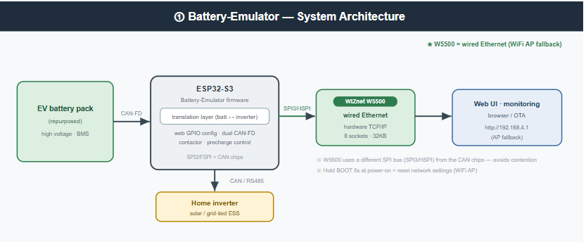
Data from the EV battery pack enters the ESP32-S3 (translation layer) over CAN-FD; the ESP32-S3 talks to the home inverter over CAN/RS485 on one side and drives the W5500 over SPI3/HSPI on the other to provide the web UI / monitoring / OTA network. The W5500 handles wired Ethernet while the WiFi AP stays as a fallback, and the CAN chips use a separate SPI bus (SPI2/FSPI). In short, "battery↔inverter translation" and "wired-network observation" run on separate paths on one board.
② Web GPIO Configuration Flow
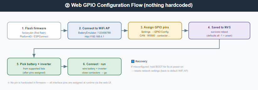
The sequence is: flash firmware → connect to the WiFi AP (192.168.4.1) → assign GPIO pins in the web UI (CAN, W5500, contactors, etc.) → saved to NVS (survives reboot) → pick battery & inverter type → connect and run. The key point is that no pin is hardcoded in firmware — every interface pin is assigned at runtime via the web UI, and if things get misconfigured you can hold BOOT for 5 s at power-on to recover the default WiFi AP mode.
③ Network & SPI Bus Separation
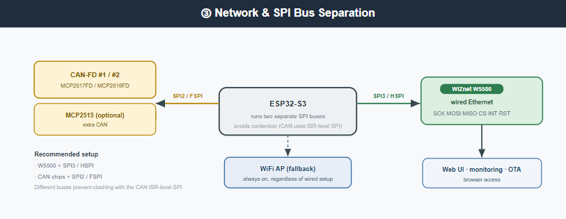
This shows why the ESP32-S3 runs two separate SPI buses. Because the CAN chips use ISR-level SPI, the design splits them — CAN chips = SPI2/FSPI, W5500 = SPI3/HSPI — to avoid bus contention. The W5500 provides wired Ethernet for web UI, monitoring, and OTA, while the WiFi AP is always kept as a fallback regardless of the wired setup.
⚠️ Safety Note (High Voltage · Prototype)
This project involves high-voltage EV batteries and grid-tied inverters. High-voltage work carries shock, fire, and fatal-injury risk; always follow your local laws and consult a licensed electrician if unsure. The fork's author also explicitly states the firmware is prototype, AI-assisted, unreviewed, unwarranted, and unfit for safety-critical/production use. This write-up is an introduction and does not replace proper safety design and certification.
Similar Project
https://maker.wiznet.io/gunn/projects/esp32-s3-ethernet-w5500-modbus-tcp-connect-to-modbus-poll/
Both projects exchange Modbus over Ethernet using an ESP32-S3 + W5500 and deal with voltage/current/temperature data. gunn's project implements Modbus TCP on an ESP32-S3 + W5500, mapping voltage/current/temperature/alarm data to Modbus addresses (connects to Modbus Poll; aimed at industrial automation / SCADA). Battery-Emulator, however, is a complete EV-battery↔inverter translation layer (ESS) that also includes dual CAN-FD, web GPIO config, and web UI/OTA.
| Item | Battery-Emulator (fork) | ESP32-S3 W5500 Modbus TCP (gunn) |
|---|---|---|
| Purpose | EV battery reuse (ESS) | Modbus TCP data transmission demo |
| MCU | ESP32-S3 | ESP32-S3 |
| Network | W5500 wired (+WiFi fallback) | W5500 wired |
| Main comms | CAN-FD/RS485/Modbus | Modbus TCP |
| Data | cell voltage/current/temp/fault | voltage/current/temp/alarm |
| Scope | battery/inverter control + web UI | industrial automation / SCADA |
For closer battery-themed references (external, not on maker.wiznet.io):
ai-republic/bms-to-inverter(generic BMS↔inverter bridge),vladyspavlov/esphome-must-inverter(ESP32 inverter+battery monitor),syssi/esphome-seplos-bms(ESP32 BMS cell monitoring). Note these are not maker.wiznet.io posts and do not use the W5500.
FAQ
Q: What is this project? A: Open-source firmware that translates between an EV battery and an inverter so EV packs can be reused as home energy storage; this repo is a fork adding generic ESP32-S3 + W5500 Ethernet support.
Q: How is the W5500 used? A: It provides wired Ethernet (web UI, monitoring, OTA). SPI pins are assigned via the web UI, on a different SPI bus from the CAN chips (recommended SPI3/HSPI). WiFi AP remains as fallback.
Q: Why wired Ethernet? A: It's more reliable than WiFi for an always-on device like a home ESS; the W5500's hardware TCP/IP improves stability.
Q: Can I use it in production right away? A: No. The author states it's prototype, AI-assisted, uncertified code, and the high-voltage risk is significant. Follow safety regulations and consult a professional.