
[ PS-NET002 ] UDP Hoist Converter Using W5500 Wired Ethernet
PS-NET002 is a W5500-based wired UDP hoist controller for stable industrial communication.
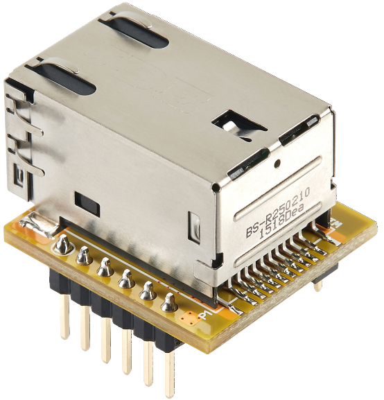
WIZnet - WIZ850io
x 1
PS-NET002:
안녕하세요! 오늘은 전파 방해가 심한 산업 현장, 특히 와이파이 사용이 불가능한 발전시설공단 등에서 핵심적인 역할을 수행할 유선 네트워크 제어 보드 'PS-NET002'를 소개해 드립니다.
1. PS-NET002 개발배경
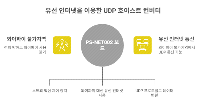
일반적인 스마트 팩토리 환경에서는 와이파이를 이용해 장비를 제어하지만, 발전소나 대형 플랜트는 보안 및 설비 특성상 강력한 전파 방해 시스템이 작동하여 무선 통신이 끊기는 경우가 많습니다.
PS-NET002는 이러한 와이파이 불가지역에서 유선 인터넷(W5500)을 활용해 안정적으로 UDP 프로토콜을 변환하고 장치를 제어하기 위해 설계되었습니다.
2. 핵심 하드웨어 사양 및 핀맵
- Main MCU: ESP32-C3 Super Mini (컴팩트하지만 강력한 성능)
- Network: W5500 기반 RJ45 유선 인터넷 커넥터 지원
- Interface: * OLED 디버깅 출력 지원
- I2C 확장 포트 (센서 및 모듈 확장 용이)
- UART를 통한 AT 모드/UWB 모듈 제어
- Built-in: 테스트용 버튼 2개 및 부저(Buzzer) 내장
개발 및 유지보수를 위한 주요 GPIO 할당 표입니다.
| 구분 | 기능 | ESP32-C3 GPIO | 비고 |
|---|---|---|---|
| W5500 (SPI) | MISO, MOSI, SCK, CS | GPIO 5, 6, 4, 7 | 유선 이더넷 제어 |
| 디지털 출력 | OUT1, OUT2 | GPIO 1, 10 | 크레인 CAM1, CAM2 제어 |
| 상태 알림 | BUZZER | GPIO 8 | 비프음 출력 |
| 사용자 입력 | SW1, SW2 | GPIO 9, 0 | INPUT_PULLUP 사용 |
| 통신/확장 | I2C (SDA, SCL) | GPIO 2, 3 | 센서 확장용 |
| 통신/확장 | UART (RXD, TXD) | GPIO 20, 21 | 외부 모듈 제어 |
3. 주요 기능 및 작동 원리
이 보드는 유선으로 수신된 UDP 데이터를 분석하여 하드웨어 접점 신호로 바꿔주는 역할을 합니다.
- UDP 프로토콜 변환: 수신된 명령(
S1E,S2E등)에 따라 출력 포트(OUT1, OUT2)를 제어합니다. - 기존 장비 호환: 보드의 출력 포트를 기존 호이스트 크레인의 하드웨어 입력 포트(CAM1, CAM2)에 직접 연결하여 바로 사용할 수 있습니다.
- 양방향 피드백(Echo): 신호를 받으면 송신 측으로 수신 확인(Echo) 메시지를 전달하여 통신 신뢰성을 확보합니다.
- ESPNOW 지원: 신호등 리모트 제어 등을 위한 핀맵 설정이 가능합니다.
- OLED 디버깅: 실시간 동작 상태 및 네트워크 정보를 표시하는 디스플레이 지원
- 자가 진단 도구: 테스트용 온보드 버튼(SW1, SW2) 및 상태 알림 부저(Buzzer) 내장
PS-NET002는 네트워크 신호를 물리적인 접점 신호로 변환하여 기존 크레인 시스템과 완벽하게 호환됩니다.
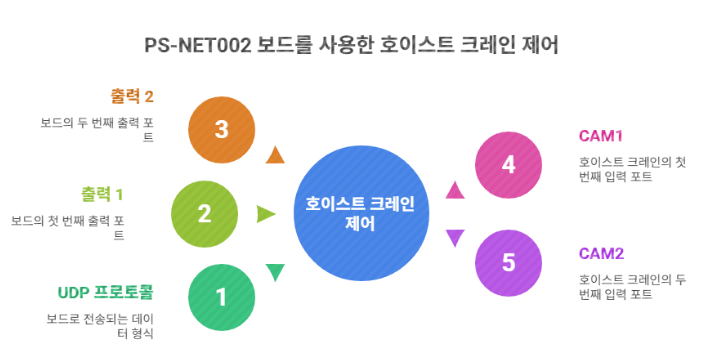
- 입력: 외부 서버나 컨트롤러로부터 UDP 프로토콜 데이터 수신
- 변환: ESP32-C3 MCU가 데이터를 해석하여 출력 1(OUT1) 또는 출력 2(OUT2) 신호 발생
- 제어: 보드의 출력을 호이스트 크레인의 하드웨어 입력 포트인 CAM1, CAM2에 연결하여 장비 구동
4. 시스템 네트워크 구성(IP 할당 예시)
현장 내 안정적인 제어를 위해 아래와 같이 고정 IP 체계로 운영됩니다.
| 장치명 | 할당 IP | 역할 |
|---|---|---|
| 서버(Main) | 192.168.99.100 | 전체 시스템 관제 |
| 호이스트 제어기(유선) | 192.168.99.111 | PS-NET002 본체 |
| 카메라 1/2 | 192.168.99.101~102 | 현장 모니터링 |
| 경광타워/안전장구 | 192.168.99.120~130 | 안전 알림 및 작업자 위치 확인 |
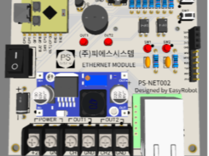
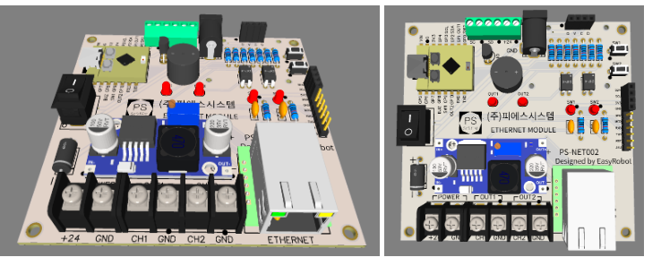
PS-NET002는 +24V 전원 입력을 지원하며, CH1(CAM1), CH2(CAM2) 단자를 통해 크레인과 직결됩니다. 콤팩트한 사이즈에 견고한 터미널 블록이 적용되어 산업 현장의 제어 판넬 내부에 설치하기 최적화되어 있습니다.
5. 핵심 코드 가이드 (Arduino /ESP32)
개발자를 위한 주요 로직 요약입니다. Ethernet.h와 EthernetUdp.h를 사용하여 W5500을 제어합니다.
// UDP 명령 처리 예시
if(packetBuffer[0]=='S' && packetBuffer[2]=='E'){
  if(packetBuffer[1]=='1'){        // 1번 출력 활성화
    udp_out1=false; udp_out2=true;
    tone(BUZZ,2000,80);
  }
  else if(packetBuffer[1]=='2'){   // 2번 출력 활성화
    udp_out1=true; udp_out2=false;
    tone(BUZZ,2500,80);
  }
  else if(packetBuffer[1]=='0'){   // 정지/OFF
    udp_out1=false; udp_out2=false;
    tone(BUZZ,1500,120);
  }
}
6. 결론
PS-NET002는 무선 통신이 제한된 가혹한 산업 환경에서 호이스트 크레인을 안전하고 정확하게 제어할 수 있는 최적의 솔루션입니다. 유선 네트워크의 안정성과 ESP32-C3의 확장성을 동시에 경험해 보세요!
FAQ
Q: 왜 W5500을 사용하나요?
A: 이 프로젝트는 Wi-Fi가 불가능하거나 불안정한 환경을 전제로 합니다. W5500을 사용하면 유선 Ethernet 기반으로 안정적인 UDP 통신이 가능하며, RF 간섭이나 보안 정책의 영향을 받지 않습니다.
Q: ESP32-C3에 어떻게 연결하나요?
A: W5500은 SPI 인터페이스로 연결되며, MISO, MOSI, SCK, CS 핀을 사용합니다. RJ45 커넥터를 통해 물리적인 네트워크 연결이 이루어집니다.
Q: 이 프로젝트에서 W5500의 역할은 무엇인가요?
A: 산업 네트워크에서 UDP 제어 패킷을 수신하여 ESP32-C3로 전달하는 역할을 합니다. 이후 MCU가 이를 해석해 실제 장비 제어 신호로 변환합니다.
Q: 초보자도 구현할 수 있나요?
A: 기본적인 SPI 통신, IP 네트워크, UDP 개념을 이해하고 있다면 접근 가능합니다. 다만 산업 장비와의 인터페이스까지 포함하면 중급 이상의 임베디드 경험이 필요합니다.
Q: Wi-Fi 기반 시스템과 비교하면 어떤 차이가 있나요?
A: Wi-Fi는 설치는 간편하지만 간섭과 지연이 불규칙합니다. 반면 Ethernet은 지연이 일정하고 연결 안정성이 높아 산업 제어와 같은 환경에서는 더 적합합니다.
PS-NET002: Wired UDP Hoist Converter for Overcoming Wi-Fi Dead Zones
Hello! Today, we are introducing the PS-NET002, a wired network control board designed to play a critical role in industrial sites with severe radio interference—specifically areas like power plant facilities where Wi-Fi usage is restricted or impossible.
1. Development Background
In standard Smart Factory environments, equipment is typically controlled via Wi-Fi. However, power plants and large-scale industrial facilities often operate signal jamming/interference systems for security and operational reasons, leading to frequent wireless connection drops.
The PS-NET002 was engineered to utilize Wired Ethernet (W5500) to stably convert UDP protocols and control devices in these Wi-Fi-restricted zones.
2. Core Hardware Specifications & Pinout
- Main MCU: ESP32-C3 Super Mini (Compact yet powerful performance)
- Network: W5500-based RJ45 Wired Ethernet connector support
- Interfaces: * OLED Debugging output support
- I2C Expansion port (Easy for sensors and module expansion)
- UART for AT Mode / UWB module control
- Built-in Features: 2 Test buttons and a Buzzer for status alerts
GPIO Assignment Table (for Development & Maintenance)
| Category | Function | ESP32-C3 GPIO | Remarks |
|---|---|---|---|
| W5500 (SPI) | MISO, MOSI, SCK, CS | GPIO 5, 6, 4, 7 | Wired Ethernet Control |
| Digital Output | OUT1, OUT2 | GPIO 1, 10 | Crane CAM1, CAM2 Control |
| Status Alert | BUZZER | GPIO 8 | Beep sound output |
| User Input | SW1, SW2 | GPIO 9, 0 | INPUT_PULLUP used |
| Comm/Expansion | I2C (SDA, SCL) | GPIO 2, 3 | Sensor expansion |
| Comm/Expansion | UART (RXD, TXD) | GPIO 20, 21 | External module control |
3. Key Features & Operating Principles
This board analyzes received UDP data over the wire and converts it into hardware contact signals.
- UDP Protocol Conversion: Controls output ports (OUT1, OUT2) based on received commands (e.g.,
S1E,S2E). - Legacy Equipment Compatibility: The board's output ports can be directly connected to the hardware input ports (CAM1, CAM2) of existing hoist cranes.
- Bidirectional Feedback (Echo): Upon receiving a signal, it sends a confirmation (Echo) message back to the transmitter to ensure communication reliability.
- ESPNOW Support: Pinmap configuration is available for remote control of devices like signal towers.
- OLED Debugging: Integrated display to show real-time operational status and network info.
- Self-Diagnosis Tools: On-board buttons (SW1, SW2) and a buzzer for testing and immediate feedback.
Control Flow:
- Input: Receive UDP protocol data from an external server or controller.
- Conversion: The ESP32-C3 MCU interprets the data to generate OUT1 or OUT2 signals.
- Control: The board's output is wired to the hoist crane's CAM1/CAM2 ports to drive the machinery.
4. System Network Configuration (Example IP Allocation)
For stable field control, the system operates under a fixed IP hierarchy:
| Device Name | Assigned IP | Role |
|---|---|---|
| Server (Main) | 192.168.99.100 | Total System Monitoring & Control |
| Hoist Controller (Wired) | 192.168.99.111 | PS-NET002 Main Body |
| Camera 1/2 | 192.168.99.101~102 | Site Monitoring |
| Warning Tower/Safety Gear | 192.168.99.120~130 | Safety Alerts & Worker Positioning |
The PS-NET002 supports +24V power input and connects directly to the crane via CH1(CAM1) and CH2(CAM2) terminals. Its compact size and rugged terminal blocks make it ideal for installation inside industrial control panels.
5. Core Code Guide (Arduino / ESP32)
Summary of the logic for developers using Ethernet.h and EthernetUdp.h.
// UDP Command Processing Example
if(packetBuffer[0]=='S' && packetBuffer[2]=='E'){
  if(packetBuffer[1]=='1'){        // Activate Output 1
    udp_out1=false; udp_out2=true;
    tone(BUZZ,2000,80);
  }
  else if(packetBuffer[1]=='2'){   // Activate Output 2
    udp_out1=true; udp_out2=false;
    tone(BUZZ,2500,80);
  }
  else if(packetBuffer[1]=='0'){   // Stop / OFF
    udp_out1=false; udp_out2=false;
    tone(BUZZ,1500,120);
  }
}
6. Conclusion
The PS-NET002 is the optimal solution for safely and accurately controlling hoist cranes in harsh industrial environments where wireless communication is restricted. Experience the stability of wired networking combined with the scalability of the ESP32-C3!
FAQ
Q: Why use the W5500? A: This project assumes environments where Wi-Fi is impossible or unstable. The W5500 enables reliable UDP communication via wired Ethernet, unaffected by RF interference or security policies.
Q: How is it connected to the ESP32-C3? A: The W5500 connects via the SPI interface (MISO, MOSI, SCK, CS). Physical network connectivity is provided through the RJ45 connector.
Q: What is the specific role of the W5500 in this project? A: It receives UDP control packets from the industrial network and passes them to the ESP32-C3, which then translates them into actual equipment control signals.
Q: Can a beginner implement this? A: If you understand basic SPI communication, IP networking, and UDP concepts, it is accessible. However, interfacing with industrial machinery generally requires intermediate-level embedded experience.
Q: How does it compare to Wi-Fi-based systems? A: While Wi-Fi is easier to install, it suffers from irregular latency and interference. Ethernet provides consistent latency and high connection stability, making it superior for industrial control environments.
[문의/출처] 수원 이지로봇 코딩학원 (PS-NET002 제작 및 배포)
-
ppt자료
