
Wireless Robot Controller
Wifi based microcontroller acts as a controlling the robot remotely. Multipurpose work robot is controlled and its status is identified.
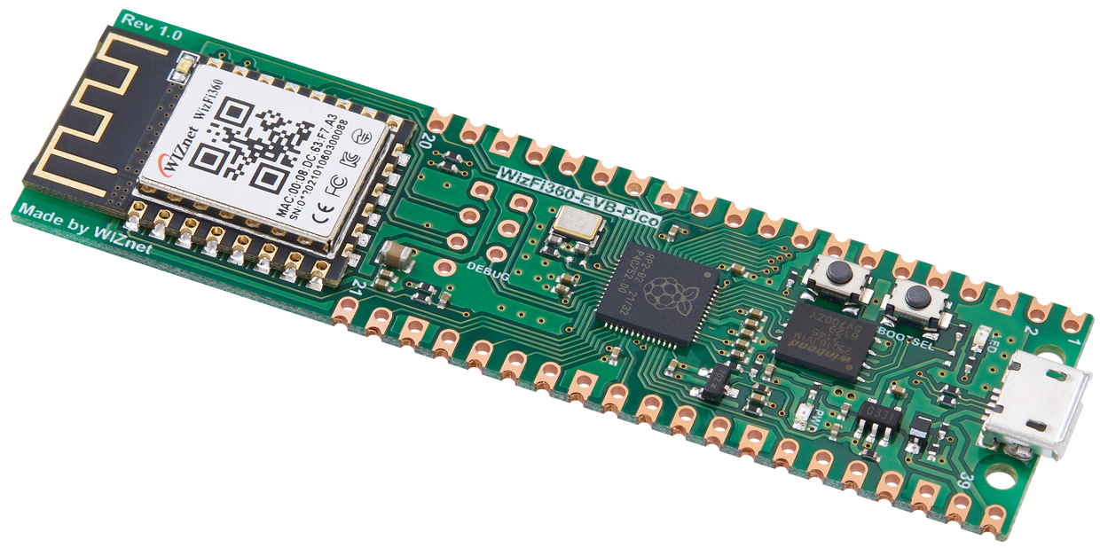
WIZnet - WizFi360-EVB-Pico
x 1
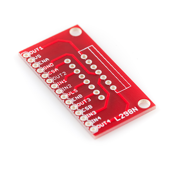
sparkfun - SparkFun Full-Bridge Motor Driver Breakout - L298N
x 1
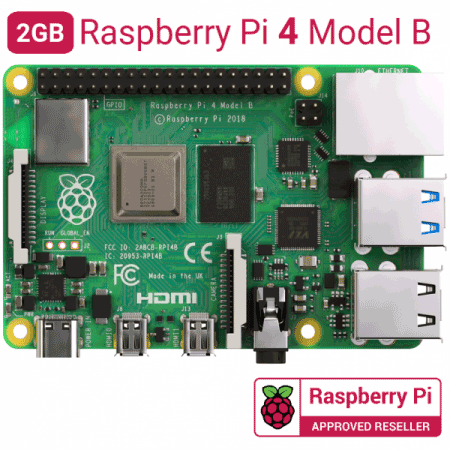
Raspberry Pi - Raspberry Pi 4 Model B
x 1

Arduino - Arduino IDE
x 1

Eclipse Foundation - Mosquitto
x 1
Mosquitto MQTT
Raspberry Pi - Raspberry Pi OS
x 1
OS for raspberry pi
Introduction:
The ability to control things by a remote control is very advantageous, I was so excited to know how it works and try it in real life. So I come out with a very nice project which is a car that can be controlled remotely by using Wi-Fi application anywhere in the world by moving joysticks in the direction you want and the car will follow.
it's a cool project and very simple and instructions are as follows:
This project is essentially made of two-part, the transmission part using the Wizfi360 EVB pico and the reception part using Raspberry Pi 4 model B which is on the robot car.
The Transmission Part:
Components used:
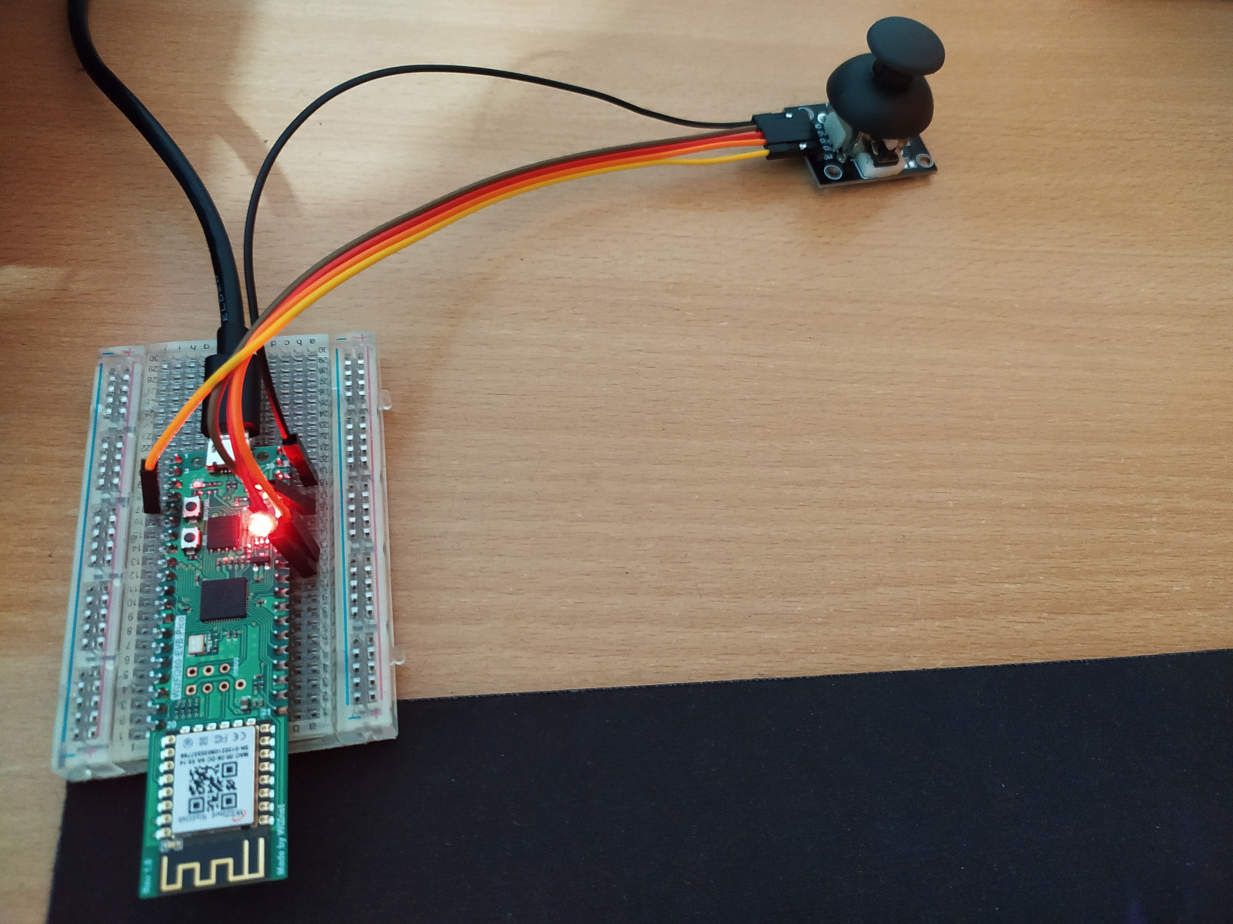
- Dual Axis XY Joystick
- Wizfi360 EVB-Pico
Software and libraries used:
- Arduino IDE
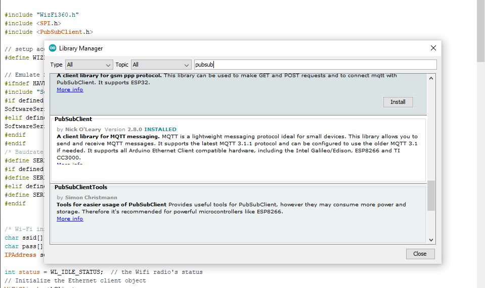
- MQTT library for Arduino IDE (PubSubClient)
For Setting up the Wizfi360 EVB pico with arduino IDe followed the instructions from this link: https://github.com/Wiznet/WizFi360_arduino_library
Installed pubsub client from the library managers in the arduino IDE:
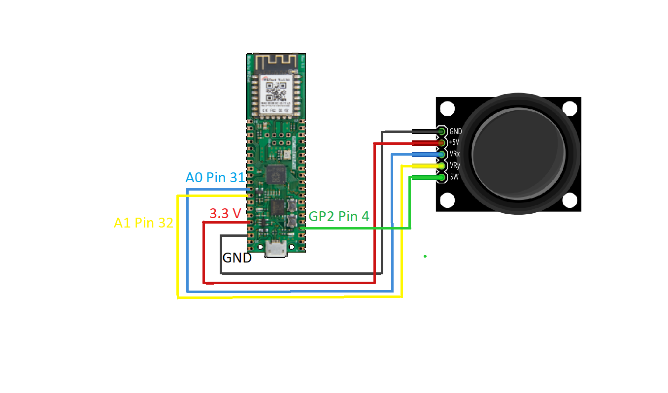
Pin connection of the Joystick with the Wizfi360 EVB Pico s shown in the table and Circuit diagram is shown below:
| Dual Axis XY Joystick | Wizfi360 (GPIO) | WizFi360 (pin Number) |
| GND | GND | PIN 38 |
| VCC | 3.3V | PIN 36 |
| VRx | A0 | PIN 31 |
| VRy | A1 | PIN 32 |
| SW | GP2 | PIN 4 |
Code explanation:
First the libraries are included for wizfi360 Wi-Fi, MQTT protocol and SPI. Then Wi-Fi connection is initiated using the library for Wizfi360 EVB pico. Details of the SSID and password of the Wi-Fi router is provided. Then MQTT is initialized as a client using Wi-Fi service
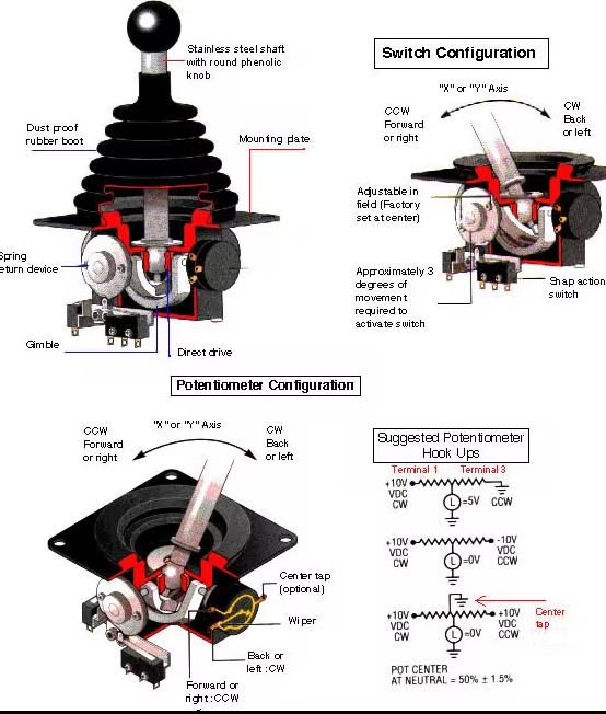
Once the Wi-Fi is initiated and connected IP address of the MQTT server is provided. ( The Mosquitto MQTT server is setup in raspberry pi 4). In my case i have given my IP address of my raspberry pi. variable are assigned to store the values of the joystick values. The working of the joystick uses the application of potentiometer and it is shown in the below image.
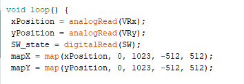
The joystick is connected to the analog pins of the Wizfi360 EVP pico and the voltage is measured as values from 0 to 1023. These 0 to 1023 values is mapped and scaled to -512 to 512 using the arduino map function.
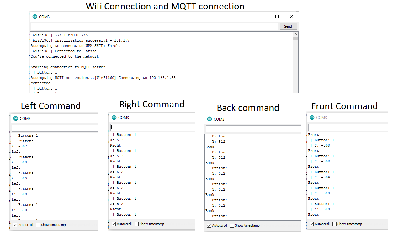
Whenever the values are obtained into the Wizfi360 EVB pico obtaining the final values as -512 to 512. The logic I've used to make is as suitable command for robot is obtained as F for forward, B as Backward, R as Right and L as Left. the logic is as follows
- If the value along the x-axis is greater then 500 then it should send 'R' (meaning its Right).
- If the value along the x-axis is less then -500, then it should send 'L (meaning its Left ).
- If the value along the y-axis is above 500, then it should send 'B' (meaning its Backward).
- If the value along the y-axis is under -500, then it should send 'F'.(meaning its forward)
Obtained values F, B, R and L are sent to the Raspberry pi using the MQTT protocol. Used MQTT publish protocol to send these commands in the topic "outTopic". The same messages are received in the raspberry pi when subscribed to this "outTopic" topic.
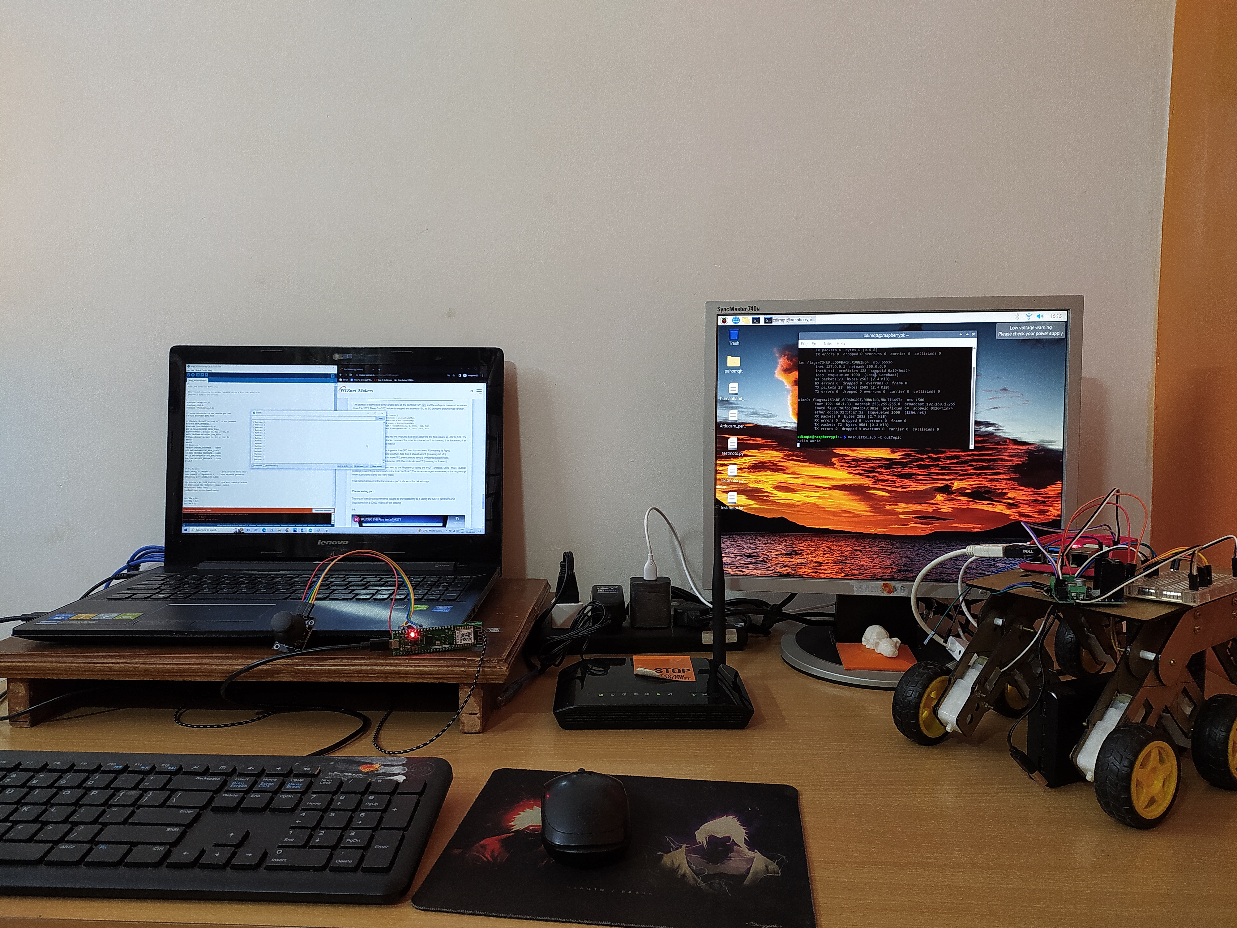
Final Output obtained in the transmission part is shown in the below image
The Receiving Part:
Testing of sending movements values to the raspberry pi 4 using the MQTT protocol and displaying it in a CMD. Video of the testing
Video of the testing:
Obtained values F, B, R and L are received in Raspberry pi using the MQTT protocol. Used MQTT subscribe protocol is used to receive these commands in the topic "outTopic".
Components used:
- TP link Wifi router
- Raspberry pi 4 model B
- L298N motor driver
- 20000 mah power bank
Software and Libraries used:
- Raspbian OS
- Mosquitto MQTT
- GPIO pins
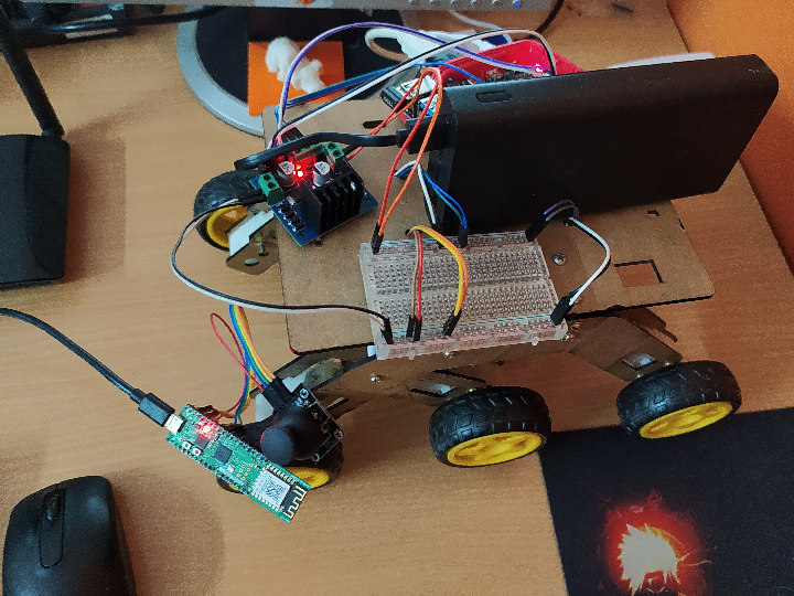
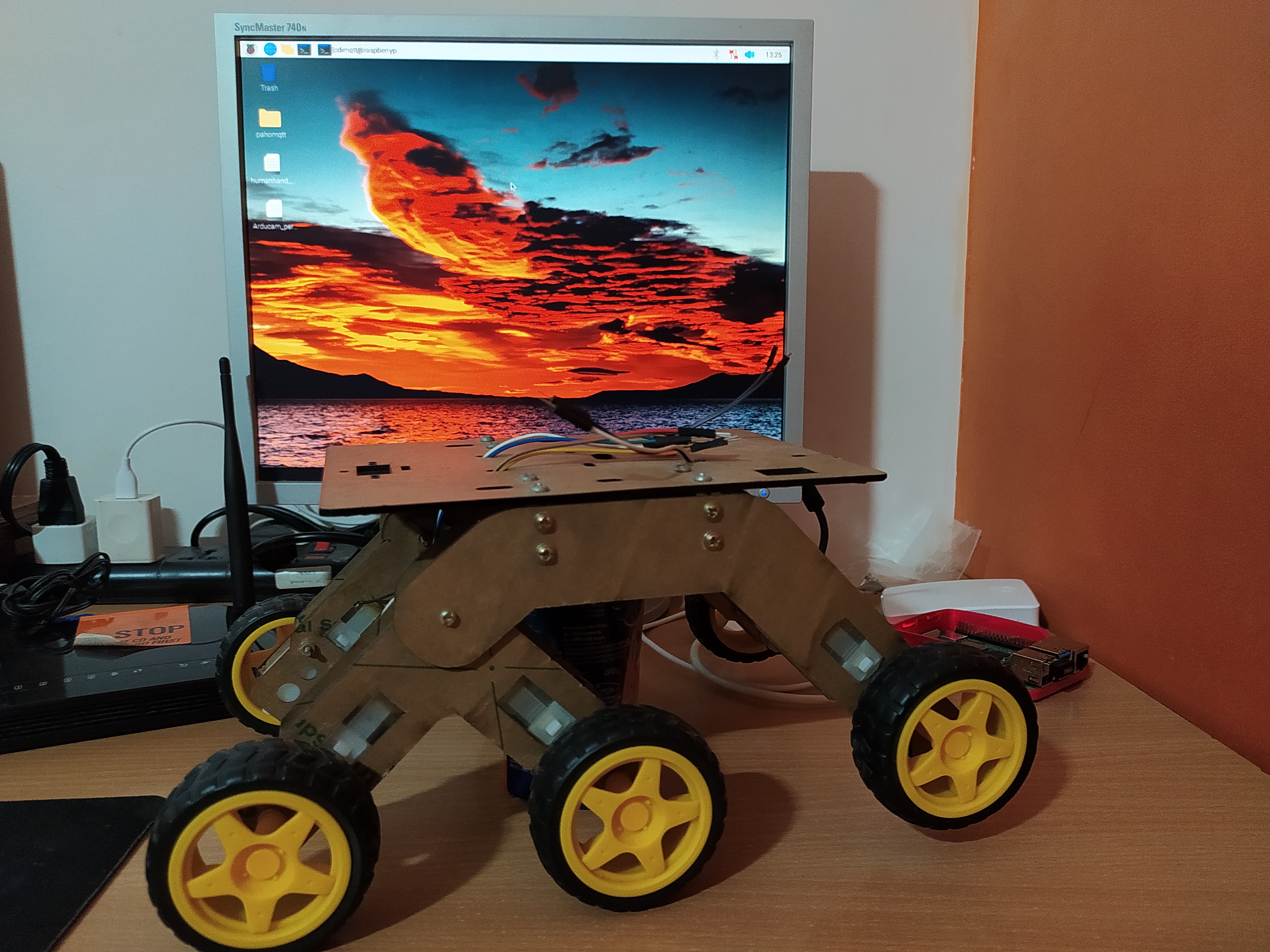
The robot vehicle:
L298N motor driver and Raspberry pi conenction details and circuit diagram:
| L298N H-bridge motor driver | R Pi4 (GPIO) |
| GND | GND |
| Input 1 | GPIO 17 |
| Input 2 | GPIO 22 |
| Input 3 | GPIO 23 |
| Input 4 | GPIO 24 |
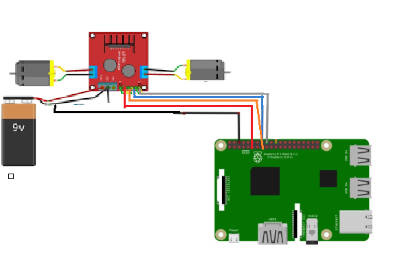
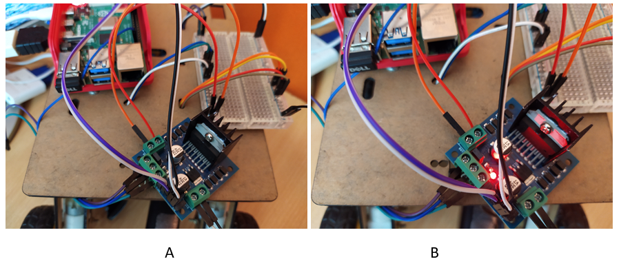
L298N motor driver connected to raspberry pi and second images is when its connected to external power supply using the power bank and the light starts glowing indicating its powered ON:
Code Explanation:
The raspberry pi is coded using python code. First MQTT library and GPIO library is included the in a while loop using the MQTT subscribe protocol, topic with the name "outTopic" is subscribed to receive the commands. the received commands are compared and corresponding movements in the robot is made. If F is received it moves forward , If R is received it is moved right side.
Then 5 functions are written to initiate the L298N motor for movements. First inputs pins of the L298N is configured then the corresponding Forward, backward, Right and Left functions are written to move in that directions.
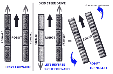
For turning the robots skid steering is used and for the Movements following logic is used:
Forward direction: All the wheels are made to go in the front direction
Backward direction: All the wheels are made to go in the reverse direction.
Left direction: The left side of the wheels are made to go in the reverse direction and right side is made to go in forward direction to turn left.
Right direction: The right side of the wheels are made to go in the reverse direction and left side is made to go in forward direction to turn right.
Project Video:
Note:
As per the video only left side of the wheels are having movements as this is made because of an intention to display the raspberry pi outputs in a display. A support is given below to lift the robot wheels from the ground and made to run.
- Arduino IDe code is the Wizfi360 EVB pico code
- Python code is the Raspberry pi code for controlling the robot movements
-
Arduino code for Wizfir360 EVB pico and raspberry pi code
