
W5500 Mini Module 3D STEP File
W5500 Mini Module 3D STEP File
CraftedTech Engineering (craftedtechengineering.com) is an engineering platform that provides circuit design assets (ECAD assets) and project guides for electronics and embedded system designers. (Philippines site)
a. Provision of Circuit Design Assets: Sells or provides symbols, footprints, and 3D models (STEP files) that can be used immediately in PCB design tools such as KiCad.
b. Project Packages: Helps users build their own projects by providing not only simple component libraries but also complete design data for specific projects, including PCB Gerber files, schematics, and Bills of Materials (BOMs).
c. Technical Blogs and Tutorials: Shares technical knowledge through blog posts on electronics manufacturing, smart solutions, and the latest engineering technologies.
This post concerns the sale and detailed description of 3D design files (STEP files) for the W5500 Mini Module. The key points can be summarized as follows: 1. Product Overview
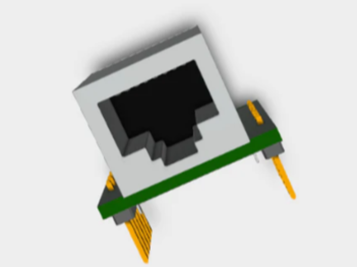
Product Name: W5500 Mini Module 3D STEP File
Applications: Provides precise 3D models for PCB design, CAD modeling, and electronic product prototyping.
Features: Creates a 3D model of a compact module equipped with the WIZnet W5500 chip, a high-performance Ethernet controller, facilitating accurate interference checks and integration during housing design or PCB placement.
2. Key Features and Benefits
Precision: Accurately reflects the module's actual dimensions and placement, making it suitable for professional PCB layout design.
Instant Download: Download immediately after purchase to shorten project development time.
Versatility: Optimized for network design in space-constrained environments, such as IoT devices, industrial control systems, and smart devices.
3. Additional Service Information (Provided by CrafteDTech Engineering)
Custom PCB Service: Provides professional PCB layout design and manufacturing Gerber file generation services upon receiving a schematic. Education & Tutorials: We operate learning resources related to engineering, including Arduino, 3D modeling, and automation systems.
In conclusion, this post is a guide introducing and selling essential 3D design assets for engineers who intend to design actual products or boards using the W5500 module.
[Q&A]
Q: How did a third party, not WIZnet, create this design file?
A: It is very common in the engineering ecosystem for third parties (such as CraftedTech Engineering), rather than manufacturers like WIZnet, to create and distribute such 3D design files. They are typically created through the following process:
a. Datasheet-based reverse engineering
This is the most standard method. The manufacturer, WIZnet, releases the datasheets for the W5500 chip and reference modules utilizing it. These contain detailed numerical data in millimeters, such as the component's width, length, height, and pin pitch. Process: Based on these figures, engineers directly model the components using 3D CAD tools such as SolidWorks, Fusion 360, and FreeCAD.
b. Physical Measurement (Based on Physical Objects)
If datasheets are inaccurate or unavailable, or if more precise details are required, engineers purchase actual modules and measure them directly using tools such as vernier calipers.
They directly measure the position of connectors, the height of LEDs, and the thickness of the PCB, incorporating these measurements into the model.
c. Combination of Component Libraries
The W5500 mini module consists of components such as the 'W5500 chip,' 'RJ45 connector,' 'resistors/capacitors,' and 'header pins.'
Engineers collect individual 3D files provided by each component manufacturer (e.g., connector manufacturers) and arrange them to create a single assembly file in the form of a completed module.
In summary, you can understand this as a "professional replica" created by engineers through precise, almost tedious, modeling work based on publicly available technical documentation and physical data.
==============================
CraftedTech Engineering(craftedtechengineering.com)은 전자 공학 및 임베디드 시스템 설계자를 위해 회로 설계 자산(ECAD 자산)과 프로젝트 가이드를 제공하는 엔지니어링 플랫폼입니다.(필리핀 사이트)
a. 회로 설계 자산 제공: KiCad와 같은 PCB 설계 툴에서 즉시 사용할 수 있는 기호(Symbols), 풋프린트(Footprints), 3D 모델(STEP 파일)을 판매하거나 제공합니다.
b. 프로젝트 패키지: 단순 부품 라이브러리뿐만 아니라, 특정 프로젝트를 위한 PCB 거버(Gerber) 파일, 회로도(Schematic), 부품 리스트(BOM) 등을 포함한 전체 설계 데이터를 제공하여 사용자가 직접 제작해 볼 수 있도록 돕습니다.
c. 기술 블로그 및 튜토리얼: 전자기기 제작, 스마트 솔루션 및 최신 엔지니어링 기술에 대한 블로그 포스팅을 통해 기술 지식을 공유합니다.
W5500 미니 모듈의 3D 설계 파일(STEP 파일) 판매 및 상세 설명에 관한 글입니다. 주요 내용은 다음과 같이 요약할 수 있습니다.
1. 제품 개요
제품명: W5500 Mini Module 3D STEP File
용도: PCB 설계, CAD 모델링, 전자제품 프로토타이핑을 위한 정밀한 3D 모델 제공.
특징: 하이퍼포먼스 이더넷 컨트롤러인 WIZnet W5500 칩이 탑재된 소형 모듈을 3D로 구현하여, 하우징 설계나 PCB 배치 시 정확한 간섭 체크와 통합이 가능하도록 돕습니다.
2. 주요 기능 및 장점
정밀성: 모듈의 실제 치수와 배치를 정확하게 반영하여 전문적인 PCB 레이아웃 설계에 적합합니다.
즉시 다운로드: 구매 후 바로 다운로드하여 프로젝트 개발 시간을 단축할 수 있습니다.
범용성: IoT 기기, 산업용 제어 시스템, 스마트 기기 등 공간 제약이 있는 환경의 네트워크 설계에 최적화되어 있습니다.
3. 추가 서비스 정보 (CrafteDTech Engineering 제공)
커스텀 PCB 서비스: 사용자가 회로도(Schematic)를 보내면 전문적인 PCB 레이아웃 설계 및 제조용 거버(Gerber) 파일 제작 서비스를 제공합니다.
교육 및 튜토리얼: 아두이노, 3D 모델링, 자동화 시스템 등 엔지니어링 관련 학습 리소스를 운영하고 있습니다.
결론적으로, 이 글은 W5500 모듈을 활용해 실제 제품이나 보드를 설계하려는 엔지니어들에게 필수적인 3D 설계 자산(Asset)을 소개하고 판매하는 안내글입니다.
[Q&A]
Q: 이 설계 파일을 위즈네트가 아닌 제 3자가 어떻게 만들었지?
A: 위즈네트(WIZnet)와 같은 제조사가 아닌 제 3자(CraftedTech Engineering 등)가 이러한 3D 설계 파일을 제작하여 배포하는 방식은 엔지니어링 생태계에서 매우 흔한 일입니다. 주로 다음과 같은 과정을 통해 만들어집니다.
a. 데이터시트(Datasheet) 기반 역설계
가장 표준적인 방법입니다. 제조사인 위즈네트는 W5500 칩과 이를 활용한 레퍼런스 모듈의 데이터시트를 공개합니다. 여기에는 부품의 가로, 세로, 높이, 핀 간격(Pitch) 등의 수치 데이터가 mm 단위로 상세히 기록되어 있습니다.
과정: 엔지니어는 이 수치를 바탕으로 SolidWorks, Fusion 360, FreeCAD 같은 3D CAD 툴에서 직접 모델링을 합니다.
b. 물리적 측정 (실물 기반)
데이터시트가 부정확하거나 없는 경우, 또는 더 정밀한 디테일이 필요한 경우 엔지니어가 실제 모듈을 구입해 버니어 캘리퍼스(Vernier Calipers) 등으로 직접 측정합니다.
커넥터의 위치, LED의 높이, PCB의 두께 등을 직접 재서 모델링에 반영합니다.
c. 부품 라이브러리 조합
W5500 미니 모듈은 'W5500 칩', 'RJ45 커넥터', '저항/콘덴서', '헤더 핀' 등으로 구성됩니다.
엔지니어는 각 부품 제조사(예: 커넥터 제조사)가 제공하는 개별 3D 파일을 수집한 뒤, 이를 배치하여 하나의 완성된 모듈 형태의 어셈블리(Assembly) 파일을 만듭니다.
요약하자면, 공개된 기술 문서와 실물 데이터를 바탕으로 엔지니어가 노가다(?)에 가까운 정밀한 모델링 작업을 거쳐 만든 "전문적인 복제품"이라고 이해하시면 됩니다.