


Using W5500 with CM4 + CM4IO board (CM4 + CM4IO 보드에서 W5500 사용하기)
A user on the Raspberry Pi forum resolved intermittent boot failures with a W5500 SPI Ethernet module on a CM4+CM4IO board by powering it from a separate extern

WIZnet - W5500
x 1

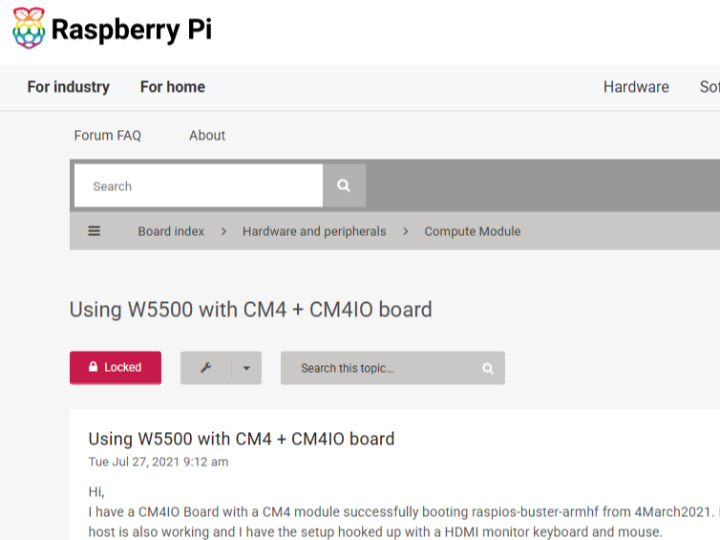
This is a troubleshooting thread on the W5500 dual Ethernet configuration on the CM4 (Compute Module 4) + CM4IO board on the Raspberry Pi official forum (raspberrypi.org).
Summary of article
problem situation
User (automata141) attempted to add a second Ethernet port (eth1) by connecting a W5500 module to the CM4+CM4IO board with a 40-pin expansion header (SPI).
An interface is created with the settings dtoverlay=w5500,int_pin=25,cs=0,speed=15000000, but a problem occurs in which actual network communication does not occur.
The same wiring/settings work normally on a regular Raspberry Pi 4 or BeagleBone, confirming that it is not a problem with the W5500 module itself or software settings.
Cause identification process
At first, the jumper wire length and 5V power line contact were suspected to be defective → Replaced with a shorter cable, temporarily resolved.
Even after this, the intermittent problem where the W5500 is not recognized recurs with a 1/5 chance when booting (a pattern of failure was discovered when the Link/Data LED on the RJ45 blinked, and success when it was permanently lit).
Instead of jumper wires, a dedicated 2-layer PCB (directly connected to the J8 header) was produced, but the problem was repeated → concluded to be a power problem, not a wiring problem.
Solution: When the W5500 module power supply was changed to a separate external 3.3V supply instead of the 5V/3.3V of the CM4 board, everything worked normally in the 100 boot test.
The last comment (Mexx) explains the root cause: The W5500 consumes about 130mA for a 100M link, but the 3.3V rail of the CM4 module is limited to 600mA, so sharing power with other components may cause power shortage (brownout).
A subsequent attempt is made to change the INT pin to GPIO7 instead of GPIO25, and the thread terminates.
Role of W5500 (in the context of this article)
In this thread the W5500 is being used as a hardwired TCP/IP controller to add a second (secondary) wired Ethernet port with an SPI interface to the CM4 board. Specifically:
Connection method: Communicates with host (CM4) via SPI (MOSI/MISO/SCLK/SSEL) + interrupt pin (INT), connects to physical network via RJ45.
Functional role: Apart from the CM4's built-in Ethernet (RGMII-based), provides a second, completely independent NIC called eth1 as an SPI bus. The Linux kernel w5500 device tree overlay recognizes this as a standard network interface.
Characteristics highlighted in this case: In order for the W5500 to operate stably, a current of approximately 130mA is required for a 100M link, and it has been empirically confirmed that exceeding the 3.3V rail capacity of the host board (CM4 is limited to 600mA) or sharing the current with other components can lead to intermittent boot failure.
In other words, this article is an example of a practical lesson that “when attaching an SPI Ethernet controller, you must check the power rail capacity of the host board” rather than the reliability of the W5500 itself. From WIZnet's perspective, it is worth referring to as actual user feedback on "power-related stability issues" that frequently occur when adopting the W5500. In particular, a separate power disconnection recommendation guide can be helpful for customers of SBC/compute module series such as CM4, which have limited 3.3V rail capacity.
=================
이번 건 Raspberry Pi 공식 포럼(raspberrypi.org)의 CM4(Compute Module 4) + CM4IO 보드에서 W5500 듀얼 이더넷 구성 트러블슈팅 스레드네요.
글 요약
문제 상황
사용자(automata141)가 CM4+CM4IO 보드에 40핀 확장 헤더(SPI)로 W5500 모듈을 연결해 두 번째 이더넷 포트(eth1)를 추가하려 시도.
dtoverlay=w5500,int_pin=25,cs=0,speed=15000000 설정으로 인터페이스는 생성되지만 실제 네트워크 통신이 안 되는 문제 발생.
동일한 배선/설정이 일반 Raspberry Pi 4나 BeagleBone에서는 정상 동작해서, W5500 모듈 자체나 소프트웨어 설정 문제가 아님을 확인.
원인 규명 과정
처음엔 점퍼선 길이·5V 전원선 접촉 불량 의심 → 짧은 케이블로 교체, 일시적으로 해결.
이후에도 부팅 시 1/5 확률로 W5500이 인식 안 되는 간헐적 문제 재발 (RJ45의 Link/Data LED가 깜빡이면 실패, 고정 점등이면 성공하는 패턴 발견).
점퍼선 대신 전용 2층 PCB(J8 헤더 직결)까지 제작했지만 문제 재현됨 → 배선 문제가 아니라 전원 문제로 결론.
해결책: W5500 모듈 전원을 CM4 보드의 5V/3.3V 대신 별도의 외부 3.3V 공급으로 바꾸자 100회 부팅 테스트에서 전부 정상 동작.
마지막 댓글(Mexx)에서 근본 원인 설명: W5500은 100M 링크 시 약 130mA를 소비하는데, CM4 모듈의 3.3V 레일은 600mA 제한이 있어 다른 부품과 전원을 공유하면 전력 부족(브라운아웃)이 발생할 수 있음.
이후 INT 핀을 GPIO25 대신 GPIO7로 바꾸려는 후속 시도가 이어지며 스레드 종료.
W5500의 역할 (이 글 맥락에서)
이 스레드에서 W5500은 CM4 보드에 SPI 인터페이스로 두 번째(보조) 유선 이더넷 포트를 추가하는 하드와이어드 TCP/IP 컨트롤러로 사용되고 있습니다. 구체적으로:
연결 방식: SPI(MOSI/MISO/SCLK/SSEL) + 인터럽트 핀(INT)으로 호스트(CM4)와 통신, RJ45로 물리 네트워크에 연결.
기능적 역할: CM4의 내장 이더넷(RGMII 기반)과는 별도로, eth1이라는 완전히 독립된 두 번째 NIC를 SPI 버스로 제공. 리눅스 커널 w5500 디바이스트리 오버레이가 이를 표준 네트워크 인터페이스로 인식시킴.
이 사례에서 부각된 특성: W5500이 안정적으로 동작하려면 100M 링크 시 약 130mA의 전류가 필요하며, 호스트 보드의 3.3V 레일 용량(CM4는 600mA 제한)을 초과하거나 다른 부품과 전류를 나눠 쓰면 간헐적 부팅 실패로 이어질 수 있다는 점이 실증적으로 확인됨.
즉 이 글은 W5500 자체의 신뢰성보다는 "SPI 이더넷 컨트롤러를 붙일 때 호스트 보드의 전원 레일 용량을 반드시 확인해야 한다"는 실무적 교훈을 보여주는 사례입니다. WIZnet 입장에서는 W5500 채택 시 자주 발생하는 "전원 관련 안정성 이슈"에 대한 실제 사용자 피드백 자료로 참고할 만합니다 — 특히 CM4처럼 3.3V 레일 용량이 제한적인 SBC/컴퓨트 모듈 계열 고객사에게 별도 전원 분리 권장 가이드가 도움이 될 수 있는 지점입니다.