
ESP32로 유선 이더넷과 PoE 완벽 마스터하기
ESP32로 유선 이더넷과 PoE 완벽 마스터하기
The following text explains the **process of building a stable web server/webcam by connecting wired Ethernet and PoE to an ESP32**.
## 1. Overall Summary
This article explains how to connect the ESP32 to a network using **wired Ethernet** rather than Wi-Fi. Wired Ethernet is generally more advantageous than Wi-Fi in terms of **stability, security, latency, and long-distance installation**, and by using **PoE (Power over Ethernet)**, you can handle **data communication and power supply** simultaneously with a single LAN cable.
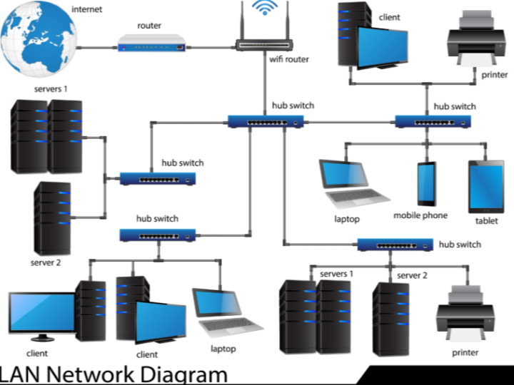
The first part explains the basic concepts of Ethernet. Ethernet data is transmitted in the form of packets, and **routers** and **switches** are important network devices. Routers connect different networks based on IP addresses, while switches connect devices within the same network based on MAC addresses.
The following section explains the selection of Ethernet cables. It is emphasized that there are grades such as Cat 5e, Cat 6, and Cat 8, and that **CCA cables**—copper-coated aluminum cables—should be avoided, as their high resistance can lead to reduced signal quality and power supply stability, and there is a risk of overheating when using PoE.
In the practical session, we first connect the **W5500 Ethernet module** to the ESP32 via SPI. After connecting the ESP32's 3.3V, GND, MOSI, MISO, SCLK, CS, and RESET pins to the W5500 module, we run an example in the Arduino IDE that uses the ETH library to automatically obtain an IP address via DHCP.
Next, we cover an example of operating the ESP32 as an **Ethernet web server**. An HTML page is stored as a string within the code, and accessing the ESP32's IP address in a browser displays the corresponding HTML page. This demonstrates that it is possible to create a small embedded web server that is more stable than Wi-Fi.
The latter part explains the **principles of PoE**. In PoE, the device supplying power is called the **PSE**, and the device receiving power is called the **PD**. The PSE does not supply power directly; instead, it safely supplies power through stages of detection, classification, power delivery, and monitoring.
For the final project, we use Waveshare's **ESP32-S3-POE-ETH board**. This board features an RJ45 Ethernet port, PoE expansion capabilities, and a camera port, allowing you to build a PoE-based webcam without complex wiring. By removing the USB power supply and utilizing only a PoE injector and an Ethernet cable to simultaneously receive power and network connectivity, we implement webcam streaming.
---
## 2. Key Message
The core message of this article is as follows:
**The ESP32 is not a board used solely for Wi-Fi; by attaching an Ethernet chip/module such as the W5500, it can be used as a stable wired network device.** By applying PoE to this, you can build devices such as IoT web servers or IP cameras using only a single LAN cable, without a power adapter.**
In other words, this means that you can expand beyond simple hobby ESP32 projects into fields such as **industrial IoT, long-term installed sensors, security cameras, and remote monitoring devices**.
---
## 3. Defining the Role of the W5500
**The W5500 is a hardware TCP/IP Ethernet controller that enables the ESP32 to connect to a wired Ethernet network.**
To be more precise, the role of the W5500 is as follows:
### The Core Role of the W5500
**It acts as a converter between the ESP32 and the Ethernet network.**
While the ESP32 itself has built-in Wi-Fi capabilities, it generally lacks an RJ45 wired Ethernet port. Therefore, a separate Ethernet controller is required for the ESP32 to connect to a network via a LAN cable. This is where the W5500 fulfills that role.
The structure can be simplified as follows:
** ```text
ESP32 ⇄ SPI ⇄ W5500 ⇄ Ethernet PHY/RJ45 ⇄ Router/Switch/Network
```
The ESP32 communicates via **SPI** with the W5500, while the W5500 handles the actual Ethernet packet transmission and reception and TCP/IP processing.
---
## 4. Why the W5500 Is Important
The biggest feature of the W5500 is that it **embeds the TCP/IP stack in hardware**.
General network communication requires the processing of protocols such as TCP, UDP, IP, ICMP, and ARP. If MCU software handles all of this processing, the code becomes complex and consumes a lot of MCU resources.
However, the W5500 processes these functions internally within the chip. Therefore, from the perspective of the ESP32, data can be exchanged relatively simply.
In other words, the W5500 performs the following tasks:
| Function | Description |
| ----------- | ------------------------------ |
| Ethernet Connection | Connects to a wired network via a LAN cable |
| TCP/IP Processing | Handles TCP, UDP, IPv4, ICMP, ARP, etc. |
| SPI Interface | Communicates with ESP32 via high-speed SPI |
| Socket Provision | Manages multiple network connections in the form of sockets |
| Reduced MCU Burden | Reduces the burden of network stack processing |
---
## 5. The Position of the W5500 in This Article
In this article, the W5500 is the **core component of the first practical step**.
First, connect the W5500 module to a standard ESP32 board and verify the following:
1. Wire the ESP32 and W5500 via SPI.
2. Plug in the Ethernet cable.
3. Obtain an IP address via DHCP.
4. Verify that the ESP32 operates as a wired Ethernet device.
5. Subsequently, create a web server using this connection.
In other words, the W5500 is the **core interface chip that transforms the ESP32 into a wired LAN device** in this article.
---
## 6. The Relationship Between the W5500 and PoE
The important point is that **the W5500 itself is not a PoE chip**.
The W5500 is strictly an **Ethernet communication chip**.
PoE is a separate power technology that supplies power through the Ethernet cable.
Therefore, the roles can be distinguished as follows:
| Category | Role |
| -------------- | -------------------------- |
| W5500 | Responsible for Ethernet data communication |
| PoE Module/PD Circuit | Receives power from the LAN cable and converts it to 5V or 3.3V |
| ESP32 | Executes applications, web server, controls sensors/cameras |
| RJ45 Connector/Transformer | Physical Ethernet connection |
In short, **the W5500 is responsible for communication, and the PoE circuit is responsible for power**.
To build PoE cameras or PoE IoT devices, a PoE power receiving circuit is required separately from the Ethernet communication unit, such as the W5500.
---
## 7. One-Sentence Definition
**The W5500 is a hardware TCP/IP Ethernet controller that enables microcontrollers like the ESP32 to connect to wired Ethernet networks via an SPI interface and perform TCP/IP communication.**
To put it more simply:
**The W5500 is a chip that adds a LAN port to the ESP32.**
=======
아래 글은 ESP32에 유선 이더넷과 PoE를 붙여 안정적인 웹 서버/웹 카메라를 만드는 과정을 설명한 콘텐츠입니다.
1. 전체 요약
이 글은 ESP32를 Wi-Fi가 아니라 유선 이더넷으로 네트워크에 연결하는 방법을 설명합니다. 유선 이더넷은 Wi-Fi보다 일반적으로 안정성, 보안성, 지연 시간, 장거리 설치성에서 유리하고, 여기에 PoE(Power over Ethernet)를 사용하면 랜선 하나로 데이터 통신과 전원 공급을 동시에 할 수 있습니다.
초반부에서는 이더넷의 기본 개념을 설명합니다. 이더넷 데이터는 패킷 형태로 전송되며, 네트워크 장비로는 라우터와 스위치가 중요합니다. 라우터는 IP 주소를 기준으로 서로 다른 네트워크를 연결하고, 스위치는 MAC 주소를 기준으로 같은 네트워크 안의 장치들을 연결합니다.
이후에는 이더넷 케이블 선택에 대해 설명합니다. Cat 5e, Cat 6, Cat 8 같은 등급이 있으며, 특히 CCA 케이블, 즉 구리 코팅 알루미늄 케이블은 저항이 높아 신호 품질과 전원 공급 안정성이 떨어질 수 있고, PoE 사용 시 발열 위험이 있으므로 피해야 한다고 강조합니다.
실습에서는 먼저 W5500 이더넷 모듈을 ESP32에 SPI 방식으로 연결합니다. ESP32의 3.3V, GND, MOSI, MISO, SCLK, CS, RESET 핀을 W5500 모듈에 연결한 뒤, Arduino IDE에서 ETH 라이브러리 등을 사용해 DHCP로 IP 주소를 자동 할당받는 예제를 실행합니다.
그다음에는 ESP32를 이더넷 웹 서버로 동작시키는 예제를 다룹니다. HTML 페이지를 코드 안에 문자열로 저장하고, 브라우저에서 ESP32의 IP 주소로 접속하면 해당 HTML 페이지가 표시됩니다. 이를 통해 Wi-Fi보다 안정적인 소형 임베디드 웹 서버를 만들 수 있음을 보여줍니다.
후반부에서는 PoE의 원리를 설명합니다. PoE에서는 전원을 공급하는 장비를 PSE, 전원을 받는 장비를 PD라고 합니다. PSE는 전력을 바로 공급하지 않고, 감지, 분류, 전력 공급, 모니터링 단계를 거쳐 안전하게 전원을 공급합니다.
마지막 프로젝트에서는 Waveshare의 ESP32-S3-POE-ETH 보드를 사용합니다. 이 보드는 RJ45 이더넷 포트와 PoE 확장 기능, 카메라 포트를 갖추고 있어서 별도의 복잡한 배선 없이 PoE 기반 웹 카메라를 만들 수 있습니다. USB 전원을 제거하고 PoE 인젝터와 이더넷 케이블만으로 전원과 네트워크를 동시에 공급받아 웹캠 스트리밍을 구현합니다.
2. 핵심 메시지
이 글의 핵심은 다음과 같습니다.
ESP32는 Wi-Fi만 쓰는 보드가 아니라, W5500 같은 이더넷 칩/모듈을 붙이면 안정적인 유선 네트워크 장치로 사용할 수 있다. 여기에 PoE를 적용하면 전원 어댑터 없이 랜선 하나만으로 IoT 웹 서버나 IP 카메라 같은 장치를 만들 수 있다.
즉, 단순한 취미용 ESP32 프로젝트를 넘어서 산업용 IoT, 장기 설치형 센서, 보안 카메라, 원격 모니터링 장치 같은 분야로 확장할 수 있다는 내용입니다.
3. W5500의 역할 정의
W5500은 ESP32가 유선 이더넷 네트워크에 접속할 수 있도록 해주는 하드웨어 TCP/IP 이더넷 컨트롤러입니다.
조금 더 정확히 말하면, W5500의 역할은 다음과 같습니다.
W5500의 핵심 역할
ESP32와 이더넷 네트워크 사이의 변환기 역할을 합니다.
ESP32 자체는 Wi-Fi 기능은 내장하고 있지만, 일반적으로 RJ45 유선 이더넷 포트는 없습니다. 따라서 ESP32가 랜선을 통해 네트워크에 접속하려면 별도의 이더넷 컨트롤러가 필요합니다. 이때 W5500이 그 역할을 합니다.
구조를 단순화하면 다음과 같습니다.
ESP32 ⇄ SPI ⇄ W5500 ⇄ Ethernet PHY/RJ45 ⇄ 공유기/스위치/네트워크
ESP32는 W5500과 SPI 통신을 하고, W5500은 실제 이더넷 패킷 송수신과 TCP/IP 처리를 담당합니다.
4. W5500이 중요한 이유
W5500의 가장 큰 특징은 TCP/IP 스택을 하드웨어로 내장하고 있다는 점입니다.
일반적인 네트워크 통신에서는 TCP, UDP, IP, ICMP, ARP 같은 프로토콜 처리가 필요합니다. 이런 처리를 MCU 소프트웨어에서 모두 담당하면 코드가 복잡해지고 MCU 자원을 많이 사용합니다.
하지만 W5500은 이런 기능을 칩 내부에서 처리합니다. 그래서 ESP32 입장에서는 비교적 단순하게 데이터를 주고받을 수 있습니다.
즉, W5500은 다음 일을 해줍니다.
| 기능 | 설명 |
|---|---|
| Ethernet 접속 | 랜선을 통해 유선 네트워크에 연결 |
| TCP/IP 처리 | TCP, UDP, IPv4, ICMP, ARP 등 처리 |
| SPI 인터페이스 | ESP32와 고속 SPI로 통신 |
| 소켓 제공 | 여러 개의 네트워크 연결을 소켓 형태로 관리 |
| MCU 부담 감소 | 네트워크 스택 처리 부담을 줄임 |
5. 이 글에서 W5500의 위치
이 글에서 W5500은 첫 번째 실습 단계의 핵심 부품입니다.
처음에는 일반 ESP32 보드에 W5500 모듈을 연결해서 다음을 확인합니다.
ESP32와 W5500을 SPI로 배선한다.
이더넷 케이블을 꽂는다.
DHCP를 통해 IP 주소를 받는다.
ESP32가 유선 이더넷 장치로 동작하는지 확인한다.
이후 이 연결을 이용해 웹 서버를 만든다.
즉, W5500은 이 글에서 ESP32를 유선 LAN 장치로 바꾸는 핵심 인터페이스 칩입니다.
6. W5500과 PoE의 관계
중요한 점은 W5500 자체가 PoE 칩은 아니라는 것입니다.
W5500은 어디까지나 이더넷 통신 칩입니다.
PoE는 이더넷 케이블을 통해 전원을 공급하는 별도의 전원 기술입니다.
따라서 역할을 구분하면 다음과 같습니다.
| 구분 | 역할 |
|---|---|
| W5500 | 이더넷 데이터 통신 담당 |
| PoE 모듈/PD 회로 | 랜선에서 전원을 받아 5V 또는 3.3V로 변환 |
| ESP32 | 애플리케이션 실행, 웹 서버, 센서/카메라 제어 |
| RJ45 커넥터/트랜스포머 | 물리적인 이더넷 연결 |
즉, W5500은 통신 담당, PoE 회로는 전원 담당입니다.
PoE 카메라나 PoE IoT 장치를 만들려면 W5500 같은 이더넷 통신부와 별도로 PoE 전원 수신 회로가 필요합니다.
7. 한 문장 정의
W5500은 ESP32 같은 마이크로컨트롤러가 SPI 인터페이스를 통해 유선 이더넷 네트워크에 접속하고 TCP/IP 통신을 수행할 수 있게 해주는 하드웨어 TCP/IP 이더넷 컨트롤러입니다.
더 쉽게 말하면:
W5500은 ESP32에 랜포트를 달아주는 칩입니다.