


Crystal Oscillator Selection Guide: Types, Specs, and Packages
Crystal Oscillator Selection Guide: Types, Specs, and Packages

WIZnet - W5500
x 1

1. Key Summary
This article is not simply about "what MHz oscillator to choose," but rather a guide explaining how to select mass-producible crystal and oscillator components starting from system requirements. The core message is that a component is not suitable simply because the frequency matches; accuracy, temperature, jitter, output format, package, and availability must also be considered. ([Fly-Wing][1])
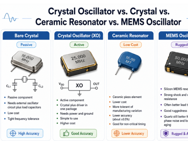
1) Difference Between Crystal and Crystal Oscillator
* Crystal, Crystal Oscillator
* It is a passive component.
* It requires an internal oscillation circuit within the IC and an external load capacitor.
* While the component price is low, the final frequency accuracy varies depending on PCB parasitic components, capacitor values, and the characteristics of the IC's oscillation circuit.
* Crystal Oscillator, XO
* It is an active component where the crystal oscillator and oscillation circuit are contained within a single package.
* A clock signal is generated simply by supplying power. * Although the price is higher, it reduces circuit design and tuning risks. ([Fly-Wing][1])
In other words, quartz oscillators are advantageous for lowering mass production costs, while finished oscillators are advantageous when design simplification and securing a stable clock are important.
2) Comparison with other frequency components
| Type | Features | Suitable Applications |
| ---------- | ------------------ | ---------------------- |
| Quartz Oscillator | Low cost, requires external oscillation circuit | MCU, existing verification circuit |
| Crystal Oscillator | Built-in oscillation circuit | Rapid development, reduced design risk |
| Ceramic Resonator | Inexpensive but low accuracy | Products where precision is not critical |
| MEMS Oscillator | Resistant to shock and vibration and programmable | Industrial, automotive, products requiring supply chain flexibility |
The text explains that, generally, quartz-based components are advantageous in phase noise and long-term aging characteristics, while MEMS have advantages in shock and vibration resistance and frequency programmability. ([Fly-Wing][1])
---
2. Differences between SPXO, TCXO, VCXO, and OCXO
A point particularly emphasized in this text is that VCXO should not be viewed simply as a class between TCXO and OCXO.
| Type | Meaning | General Characteristics | Main Applications |
| ---- | ------------ | --------------- | -------------- |
| SPXO | General package oscillator | Low cost, no temperature compensation | MCU, general digital circuits |
| TCXO | Temperature-compensated oscillator | Approx. ±0.5~±2.5 ppm | GPS, mobile communications |
| VCXO | Frequency regulation via voltage | Synchronizable to external reference | PLL, clock recovery |
| OCXO | Oscillator with built-in thermostat | ppb level stability possible | Communication infrastructure, instruments |
VCXO is not a stability class, but a function that allows frequency to be regulated via voltage. Therefore, TCVCXOs, which combine VCXO functionality with TCXOs, and OCVCXOs, which combine VCXO functionality with OCXOs, are also possible. ([Fly-Wing][1])
---
3. Items to Check When Selecting an Oscillator
① Required Frequency
First, check the reference frequency required by the system. However, simply matching the nominal frequency, such as 25 MHz or 50 MHz, is insufficient.
② Total Frequency Tolerance Budget
You should not look at just the ppm figure in the datasheet; you must sum up the following factors:
* Initial frequency tolerance
* Variation due to operating temperature
* Power supply voltage variation
* Output load variation
* Long-term aging
* Frequency variation after reflow soldering
For example, even if the datasheet states ±10 ppm, you must verify whether that value includes only temperature variation or encompasses all conditions. ([Fly-Wing][1])
③ Jitter and Phase Noise
ppm stability and jitter are different characteristics.
* ppm: Frequency shift due to long-term or temperature changes
* Jitter: Time error where clock edges momentarily fluctuate
* Phase Noise: Short-term noise characteristics appearing around frequencies
In high-speed serial communication, RF, data converters, and network equipment, problems can arise if jitter or phase noise is poor, even if ppm is sufficient. ([Fly-Wing][1])
④ Temperature and Operating Environment
The required range varies depending on whether it is for indoor, industrial, or automotive use. For industrial and outdoor equipment, an operating temperature range of −40 to 85°C or higher may generally be required, and MEMS oscillators may also be considered if vibration and shock are significant. ([Fly-Wing][1])
⑤ Output Format
You must verify what signal the receiving IC requires.
* HCMOS: General MCUs and digital circuits
* LVDS, LVPECL: High-speed differential clocks
* Clipped sine wave: RF and precision timing
You must also check voltage levels, duty cycles, and the polarity of the Enable/Standby pins. ([Fly-Wing][1])
⑥ Package and PCB Footprint
You should not make a selection based solely on external dimensions such as “3.2×2.5mm.”
* Recommended land pattern
* Pin 1 orientation
* Component height
* Precautionary areas
* SMD or DIP
* Availability of Tape & Reel, Cut Tape, and Tube supply
If these conditions are not met, PCB redesign or procurement issues may arise, even if the circuit is functioning correctly. ([Fly-Wing][1])
⑦ Supply Chain and Second Sources
Before mass production, you must secure replacement parts that match not only the same frequency but also the following conditions.
* Pin arrangement and orientation
* Supply voltage
* Output format
* Enable operation
* Stability definition
* Jitter/phase noise
* Start-up time
* Package height
* Operating temperature
In particular, OCXOs and custom frequency products have few substitutes and may have long lead times. ([Fly-Wing][1])
---
4. The Role of the W5500 in This Article
To start with the conclusion
The W5500 is not the subject of this article, but a component connected to an example of applying a crystal oscillator and an external clock to an actual IC.
The W5500 is mentioned directly once in the text. The author links it by stating, “If you want to see how load capacitance and PCB layout are handled in a specific interface IC, refer to the W5500 PCB design guide.” In other words, the W5500 is a representative example of applying oscillator selection theory to actual Ethernet IC design. ([Fly-Wing][1])
Why the W5500 Requires a Clock
The W5500 is WIZnet's hardware TCP/IP Ethernet controller that integrates the following functions:
* 10/100 Ethernet MAC
* Ethernet PHY
* Hardware TCP/IP Stack
* 8 Hardware Sockets
* SPI Interface for MCU Connection
A 25MHz reference clock is required for the Ethernet PHY and related circuitry inside the W5500 to operate. ([Fly-Wing][2])
Two Clock Configuration Methods for the W5500
Method 1: Using a 25MHz Crystal Oscillator
Connect a 25MHz crystal oscillator between the XI and XO pins of the W5500 and place load capacitors on both sides.
The structure is roughly as follows:
`W5500 XI — 25MHz Crystal — W5500 XO`
Then, connect the capacitors on both the XI and XO to GND.
In this method, the following are important:
* Crystal oscillator Load Capacitance specifications
* External capacitor value
* PCB parasitic capacitance
* XI/XO pattern length
* Separation from digital signals
* Ground guard and noise isolation
The connected Fly-Wing W5500 guide explains that the crystal oscillator and capacitor should be placed close to the pins, the clock pattern should be short, and other digital signals should not be placed nearby. ([Fly-Wing][2])
Method 2: Using an External 25MHz CMOS Oscillator
You can also input a separate 25MHz oscillator output to the W5500's `XI/CLKIN` pin.
In this case:
* External Oscillator Output → XI/CLKIN
* XO Pin → Not Connected
Although this method increases component costs, it can reduce the burden of calculating load capacitance and verifying oscillation stability for the crystal oscillator circuit. ([Fly-Wing][2])
---
5. Interpreting the content of the article from the perspective of the W5500
| Selection Criteria | Significance in the W5500 |
| ------------- | -------------------------------------------- |
| Frequency | 25MHz reference clock required |
| Crystal/XO Distinction | Selection of Crystal Oscillator or External CMOS Oscillator |
| Load Capacitance | Consider external capacitors and PCB parasitic components when using a crystal oscillator |
| Output Format | Verify the CMOS clock that XI/CLKIN can accept when using an external oscillator |
| Temperature Stability | For industrial W5500 equipment, verify clock stability at full operating temperature |
| Jitter & Phase Noise | Clock quality management for stable transmission and reception of Ethernet PHY |
| PCB Layout | Place crystal and capacitor close to XI/XO pins |
| Second Source | Securing replacements that match not only the same frequency but also CL, ESR, tolerances, and package |
Final Summary
The key points of this article are as follows:
> Crystal oscillators are simple
==================
1. 글의 핵심 요약
이 글은 단순히 “몇 MHz짜리 발진기를 고를 것인가”가 아니라, 시스템 요구사항에서 출발해 양산 가능한 크리스털·오실레이터 부품을 선정하는 방법을 설명한 가이드입니다. 핵심 메시지는 주파수만 맞는다고 적합한 부품은 아니며, 정확도·온도·지터·출력 형식·패키지·공급 가능성까지 함께 검토해야 한다는 것입니다. (Fly-Wing)
1) 크리스털과 크리스털 오실레이터의 차이
Crystal, 수정진동자
수동소자입니다.
IC 내부의 발진 회로와 외부 로드 커패시터가 필요합니다.
부품 가격은 낮지만, PCB 기생성분과 커패시터값, IC의 발진 회로 특성에 따라 최종 주파수 정확도가 달라집니다.
Crystal Oscillator, XO
수정진동자와 발진 회로가 한 패키지 안에 들어 있는 능동소자입니다.
전원만 공급하면 클록 신호가 나옵니다.
가격은 더 높지만 회로 설계와 튜닝 위험을 줄여줍니다. (Fly-Wing)
즉, 양산단가를 낮추려면 수정진동자, 설계 단순화와 안정적인 클록 확보가 중요하면 완제품 오실레이터가 유리합니다.
2) 다른 주파수 소자와의 비교
| 종류 | 특징 | 적합한 용도 |
|---|---|---|
| 수정진동자 | 저가, 외부 발진회로 필요 | MCU, 기존 검증 회로 |
| 크리스털 오실레이터 | 발진회로 내장 | 빠른 개발, 설계 위험 축소 |
| 세라믹 공진자 | 저렴하지만 정확도가 낮음 | 정밀도가 중요하지 않은 제품 |
| MEMS 오실레이터 | 충격·진동에 강하고 프로그램 가능 | 산업·자동차·공급망 유연성이 필요한 제품 |
글에서는 일반적으로 수정 기반 부품이 위상잡음과 장기 에이징 특성에서 유리하고, MEMS는 충격·진동 내성과 주파수 프로그램 가능성에서 장점이 있다고 설명합니다. (Fly-Wing)
2. SPXO·TCXO·VCXO·OCXO의 차이
글에서 특히 강조하는 부분은 VCXO를 단순히 TCXO와 OCXO 사이의 등급으로 보면 안 된다는 점입니다.
| 종류 | 의미 | 일반적 특성 | 주요 용도 |
|---|---|---|---|
| SPXO | 일반 패키지 오실레이터 | 저가, 온도 보상 없음 | MCU, 일반 디지털 회로 |
| TCXO | 온도보상 오실레이터 | 약 ±0.5~±2.5 ppm | GPS, 휴대통신 |
| VCXO | 전압으로 주파수 조정 | 외부 기준에 동기화 가능 | PLL, 클록 복구 |
| OCXO | 항온조 내장 오실레이터 | ppb 수준 안정도 가능 | 통신 인프라, 계측기 |
VCXO는 안정도 등급이 아니라 주파수를 전압으로 조절할 수 있는 기능입니다. 따라서 TCXO에 VCXO 기능을 결합한 TCVCXO, OCXO에 결합한 OCVCXO도 가능합니다. (Fly-Wing)
3. 오실레이터 선정 시 실제로 확인할 항목
① 필요한 주파수
가장 먼저 시스템이 요구하는 기준주파수를 확인합니다. 하지만 25MHz, 50MHz처럼 명목 주파수만 맞추는 것으로는 부족합니다.
② 전체 주파수 오차 예산
데이터시트의 ppm 숫자 하나만 보면 안 되고 다음 요소를 합산해야 합니다.
초기 주파수 허용오차
동작온도에 따른 변화
전원전압 변화
출력 부하 변화
장기 에이징
리플로우 납땜 후 주파수 변화
예를 들어 데이터시트에 ±10ppm이라고 적혀 있더라도, 그것이 온도 변화만 포함한 값인지 전체 조건을 포함한 값인지 확인해야 합니다. (Fly-Wing)
③ 지터와 위상잡음
ppm 안정도와 지터는 서로 다른 특성입니다.
ppm: 장기간 또는 온도 변화에 따른 주파수 이동
지터: 클록 에지가 순간적으로 흔들리는 시간 오차
위상잡음: 주파수 주변에 나타나는 단기 잡음 특성
고속 직렬통신, RF, 데이터컨버터, 네트워크 장비에서는 ppm이 충분해도 지터나 위상잡음이 나쁘면 문제가 생길 수 있습니다. (Fly-Wing)
④ 온도와 사용환경
실내용인지, 산업용인지, 자동차용인지에 따라 요구 범위가 달라집니다. 산업·옥외 장비에서는 일반적으로 −40~85°C 이상의 동작온도 범위가 필요할 수 있으며, 진동과 충격이 크다면 MEMS 오실레이터도 검토할 수 있습니다. (Fly-Wing)
⑤ 출력 형식
수신 IC가 어떤 신호를 요구하는지 확인해야 합니다.
HCMOS: 일반 MCU·디지털 회로
LVDS, LVPECL: 고속 차동 클록
Clipped sine wave: RF 및 정밀 타이밍
또한 전압 레벨, 듀티비, Enable/Standby 핀의 극성도 확인해야 합니다. (Fly-Wing)
⑥ 패키지와 PCB 풋프린트
단순히 “3.2×2.5mm”라는 외형치수만 보고 선택하면 안 됩니다.
권장 랜드패턴
1번 핀 방향
부품 높이
주변 금지영역
SMD 또는 DIP
Tape & Reel, Cut Tape, Tube 공급 여부
이런 조건이 맞지 않으면 회로는 정상이어도 PCB 재설계나 조달 문제가 생길 수 있습니다. (Fly-Wing)
⑦ 공급망과 세컨드소스
양산 전에 동일한 주파수만이 아니라 다음 조건까지 일치하는 대체품을 확보해야 합니다.
핀 배열과 방향
공급전압
출력 형식
Enable 동작
안정도 정의
지터·위상잡음
기동시간
패키지 높이
동작온도
특히 OCXO나 주문형 주파수 제품은 대체품이 적고 리드타임이 길 수 있습니다. (Fly-Wing)
4. 이 글에서 W5500의 역할
결론부터 말하면
W5500은 이 글의 주제가 아니라, 수정진동자와 외부 클록을 실제 IC에 적용하는 사례로 연결된 부품입니다.
본문에서 W5500은 한 번 직접 언급됩니다. 저자는 “특정 인터페이스 IC에서 로드 커패시턴스와 PCB 레이아웃을 어떻게 처리하는지 보고 싶다면 W5500 PCB 설계 가이드를 참고하라”고 연결합니다. 즉, W5500은 오실레이터 선정 이론을 실제 Ethernet IC 설계에 적용하는 대표적인 사례입니다. (Fly-Wing)
W5500에서 클록이 필요한 이유
W5500은 WIZnet의 하드웨어 TCP/IP Ethernet 컨트롤러로서 다음 기능을 통합합니다.
10/100 Ethernet MAC
Ethernet PHY
하드웨어 TCP/IP 스택
8개 하드웨어 소켓
MCU 연결용 SPI 인터페이스
W5500 내부의 Ethernet PHY와 관련 회로가 동작하려면 25MHz 기준 클록이 필요합니다. (Fly-Wing)
W5500의 두 가지 클록 구성 방법
방법 1: 25MHz 수정진동자 사용
W5500의 XI와 XO 핀 사이에 25MHz 수정진동자를 연결하고, 양쪽에 로드 커패시터를 배치합니다.
구조는 대략 다음과 같습니다.
W5500 XI — 25MHz Crystal — W5500 XO
그리고 XI와 XO 양쪽에서 각각 커패시터를 GND에 연결합니다.
이 방식에서는 다음이 중요합니다.
수정진동자의 Load Capacitance 사양
외부 커패시터값
PCB 기생 커패시턴스
XI/XO 패턴 길이
디지털 신호와의 이격
접지 가드 및 노이즈 차단
연결된 Fly-Wing의 W5500 가이드는 수정진동자와 커패시터를 핀 가까이에 배치하고, 클록 패턴을 짧게 하며 다른 디지털 신호를 주변에 배치하지 말라고 설명합니다. (Fly-Wing)
방법 2: 외부 25MHz CMOS 오실레이터 사용
별도의 25MHz 오실레이터 출력을 W5500의 XI/CLKIN 핀에 입력할 수도 있습니다.
이 경우:
외부 오실레이터 출력 → XI/CLKIN
XO 핀 → 연결하지 않음
이 방법은 부품비는 증가하지만 수정진동자 회로의 로드 커패시턴스 계산과 발진 안정성 검증 부담을 줄일 수 있습니다. (Fly-Wing)
5. W5500 관점에서 글의 의미
| 글의 선정 기준 | W5500에서의 의미 |
|---|---|
| 주파수 | 25MHz 기준 클록 필요 |
| Crystal/XO 구분 | 수정진동자 또는 외부 CMOS 오실레이터 선택 |
| 로드 커패시턴스 | 수정진동자 사용 시 외부 커패시터와 PCB 기생성분 고려 |
| 출력 형식 | 외부 오실레이터 사용 시 XI/CLKIN이 받아들일 수 있는 CMOS 클록 확인 |
| 온도 안정도 | 산업용 W5500 장비라면 전체 동작온도에서 클록 안정성 확인 |
| 지터·위상잡음 | Ethernet PHY의 안정적인 송수신을 위해 클록 품질 관리 |
| PCB 레이아웃 | 크리스털과 커패시터를 XI/XO 핀 가까이에 배치 |
| 세컨드소스 | 동일 주파수뿐 아니라 CL, ESR, 허용오차, 패키지가 맞는 대체품 확보 |
이 글의 핵심은 다음과 같습니다.
크리스털 오실레이터는 단순한 주파수 부품이 아니라 시스템의 정확도, 통신 안정성, PCB 설계, 양산 조달까지 좌우하는 핵심 부품이다.
W5500은 이 원칙을 보여주는 좋은 사례입니다. W5500 자체가 Ethernet 통신을 처리하지만, PHY와 내부 네트워크 회로가 정상적으로 동작하려면 안정적인 25MHz 기준 클록이 필요합니다. 따라서 W5500 설계자는 단순히 “25MHz 크리스털”을 선택하는 데 그치지 않고, 로드 커패시턴스, 주파수 오차, ESR, 온도 특성, PCB 배치와 대체 공급원까지 확인해야 합니다.
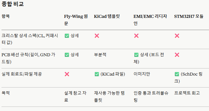
6. Maker 사이트 내 유사한 비교 글들.
1) "W5500 Ethernet Controller Schematic For KiCad" (Benjamin, 2026.1)
- 터키 엔지니어가 만든 KiCad용 W5500 참조 회로도 템플릿(GitHub 공개)
- 크리스탈 오실레이터 회로, RJ45 잭(마그네틱 포함), 전원 디커플링, 부품 사양을 포함하지만 완성된 PCB 레이아웃은 아니라고 명시
- 0603 패키지, X7R 커패시터(W5500이 약 40°C에서 동작하므로 온도 안정성 확보), EXRES1(12.4kΩ)과 종단저항(49.9Ω)에 ±1% 정밀도가 필요하다는 실전 부품 선정 팁 제공
- Fly-Wing 글과 차이점: Fly-Wing은 크리스탈 자체의 부하 커패시턴스 계산·PCB 배선 길이(5mm)·GND 가드링 등 "이론적 설계 규칙"에 집중한 반면, 이 글은 "바로 쓸 수 있는 실제 회로도 파일"을 제공하는 실무형 템플릿이라 크리스탈은 여러 구성요소 중 하나로만 언급되고 세부 규격(로드 커패시턴스 값 등)은 다루지 않음.
2) "Delving into Ethernet Board Design: Optimizing PCB with W5500 Chip" (bruno, 2024.1, 원문은 Reddit)
- 4레이어(신호-그라운드-전원-신호) 스택업의 50x38mm W5500+Atmega4809 보드를 EMI/EMC 인증(CISPR 32, FCC Class B 등) 통과 목적으로 재설계한 사례
- 보드 4개 레이어 전체에 걸쳐 PCB 가장자리에 GND 가드링을 비아 스티칭이나 도금 엣지로 구현하라는 제안, 레이어 3/4의 그라운드 플레인 배치 교체 및 신호 비아 옆 그라운드 스티칭 비아 추가 권고
- Fly-Wing 글과 차이점: Fly-Wing이 크리스탈 회로 하나에 초점을 맞춘 "부품 레벨" 가이드라면, 이 글은 EMI/EMC 인증 통과라는 "보드 전체 레벨" 관점에서 크리스탈을 포함한 전체 레이아웃(스택업, 그라운드 전략, RJ45 배치 등)을 다룸. 다만 크리스탈 자체의 로드 커패시턴스 계산 같은 세부 스펙은 없고, 실제 커뮤니티 피드백(Reddit 댓글) 기반의 트러블슈팅 성격이 강함.
3) "Designing an Ethernet Module by Connecting a W5500 to an STM32H7 100-Pin MCU (Circuit Design Section)" (bruno, 2024.2)
- STM32H743VIT6과 W5500을 연결한 이더넷 모듈 설계기로, 회로는 WIZnet 공식 하드웨어 설계 가이드와 참조 회로도, W5500-EVB-Pico 자료를 기반으로 설계
- W5500과 STM32H7의 SPI 연결, USB-C 커넥터 설계 경험을 소개하는 프로젝트 로그 형식
- Fly-Wing 글과 차이점: 이 글은 크리스탈/오실레이터에 대한 구체적 설명 없이 "WIZnet 공식 가이드를 참고했다"는 언급 수준에 그침. Fly-Wing처럼 크리스탈 부하 커패시턴스·GND 가드링·배선 길이 규칙 등 상세 엔지니어링 근거는 제공하지 않으며, 전체 모듈 설계 과정을 캐주얼하게 기록한 블로그형 글임.
[Q&A]
[Q]W5500 회로에서 25MHz 크리스털을 선택할 때 주파수만 같으면 아무 제품이나 사용할 수 있나요?
[A]
아닙니다. 25MHz라는 주파수 외에도 크리스털의 로드 커패시턴스(CL), 주파수 허용오차, ESR, 동작온도, 패키지 크기를 함께 확인해야 합니다. 특히 CL 값은 외부 커패시터와 PCB 기생 커패시턴스에 영향을 받으므로, W5500 데이터시트의 권장 회로와 크리스털 제조사의 사양을 함께 검토해야 합니다. 부품값이나 PCB 배치가 적절하지 않으면 발진이 불안정하거나 Ethernet 통신 오류가 발생할 수 있습니다.