
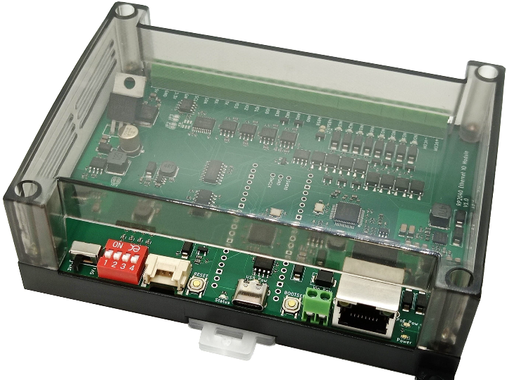
RP2040 Ethernet+PoE General-purpose IO Module
This is a general-purpose RP2040 module with PoE-compatible Ethernet and various I/O interfaces.supports various power supplies such as PoE/USB/DC9 to 27V.

WIZnet - W5500
x 1
This is a general-purpose RP2040 module with PoE-compatible Ethernet and various I/O interfaces. It is equipped with
photocoupler isolated NPN I/O, -10V to +10V/4mA to 20mA analog input, I2C compatible Grove compatible connector, RS-485 interface, etc., and supports various power supplies such as PoE/USB/DC9 to 27V. It is
also housed in a case that can be fixed by DIN rail or screw fastening, making it easy to install.
Users can freely program it according to their application.
Features
- Supports various power sources such as PoE/USB/DC9-27V
- 4 x photocoupler isolated inputs (supports current sinking outputs)
- 4 x Photocoupler isolated open collector outputs (supports current sink type)
- Supports 4 x -10V to +10V / 4mA to 20mA analog inputs (selectable per channel)
- High input impedance analog voltage input
- Equipped with Grove compatible connector for I2C
- Equipped with RS-485 serial interface
- Equipped with Raspberry Pi RP2040 (dual core, maximum clock 133MHz, 264kB SRAM)
- Equipped with 16MB of on-board flash memory
- Equipped with EEPROM (2Kbits, including 1Kbits of user writable area) with 48-bit MAC address written
- Equipped with I2C, UART and IO ports
- The signal voltage of Grove/UART/IO can be switched between 3.3V/5V
- Supports both DIN rail and screw mounting
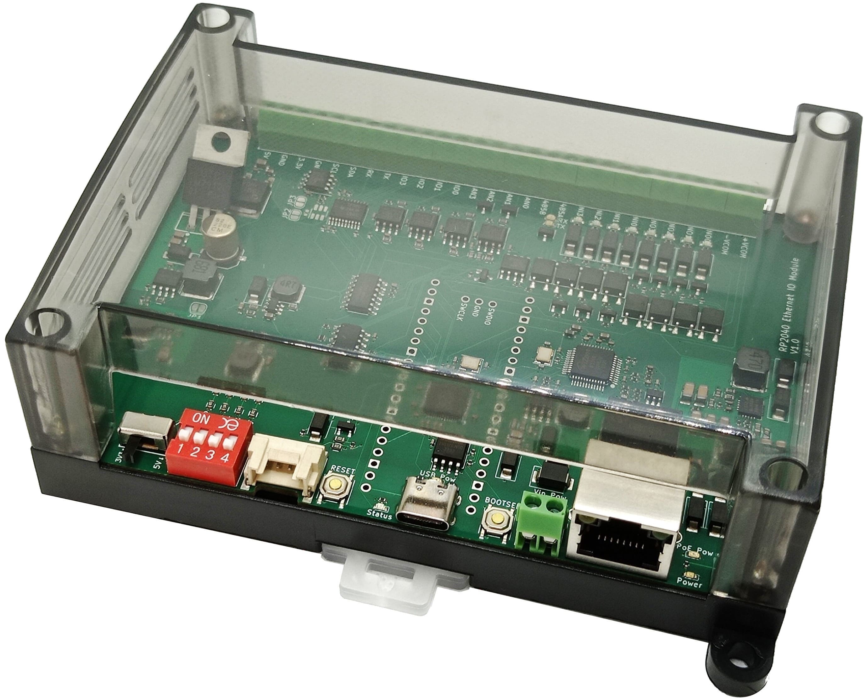
Names of each part

Contents
- Product body x 1
sale
Sales page (Switch Science)
*We may have additional stock in addition to the stock displayed on the sales page. For bulk orders or inquiries regarding stock, please contact us here .
Port description and pin assignment
| interface | Signal name( 基板シルク) | explanation | RP2040 GPIO pin numbers | RP2040 Features |
|---|---|---|---|---|
| Terminal Blocks | +VCOM | Insulated input/output positive common | - | - |
-VCOM | Negative common for isolated output | - | - | |
NO0 | Isolated NPN output CH0 | 14 | GPIO_Output | |
NO1 | Isolated NPN output CH1 | 15 | GPIO_Output | |
NO2 | Isolated NPN output CH2 | 16 | GPIO_Output | |
NO3 | Isolated NPN output CH3 | 17 | GPIO_Output | |
NI0 | Isolated NPN input CH0 | 18 | GPIO_Input | |
NI1 | Isolated NPN input CH1 | 19 | GPIO_Input | |
NI2 | Isolated NPN input CH2 | 20 | GPIO_Input | |
NI3 | Isolated NPN input CH3 | twenty one | GPIO_Input | |
485A | RS-485 signal: A | 0 | UART0_TX | |
485B | RS-485 signal: B | 1 | UART0_RX | |
AN0 | Analog Input CH0 | 26 | ADC0 | |
AN1 | Analog Input CH1 | 27 | ADC1 | |
AN2 | Analog Input CH2 | 28 | ADC2 | |
AN3 | Analog Input CH3 | 29 | ADC3 | |
IO0 | General purpose input/output CH0 | Ten | GPIO | |
IO1 | General-purpose input/output CH1 | 11 | GPIO | |
IO2 | General-purpose input/output CH2 | 12 | GPIO | |
IO3 | General purpose input/output CH3 | 13 | GPIO | |
TX | UART TX (connected to RS-485 transceiver) | 0 | UART0_TX | |
RX | UART RX (connected to RS-485 transceiver) | 1 | UART0_RX | |
SDA | I2C SDA (connected to Grove's SDA) | 8 | I2C0_SDA | |
SCL | I2C SCL (continuous with Grove's SCL ) | 9 | I2C0_SCL | |
GND | - | - | - | |
3.3V | 3.3V power output | - | - | |
GND | - | - | - | |
5V | 5V power output | - | - | |
Vin | External power input pin (DC9 to 27V) | - | - | |
GND | - | - | - | |
| Grove | SDA | I2C SDA | 8 | I2C0_SDA |
| SCL | I2C SCL | 9 | I2C0_SCL | |
| button | RESET | RP2040 Reset Button | - | RUN |
BOOTSEL | Boot mode selection button | - | - | |
| USB | D+ | USB D+ | - | USB_DP |
| D- | USB D- | - | USB_DM | |
| Ethernet | SCK | W5500 SCK | 2 | SPI0_SCK |
| MOSI | MOSI of W5500 | 3 | SPI0_TX | |
| MISO | W5500 MISO | Four | SPI0_RX | |
| CS | W5500 CS | Five | SPI0_CS | |
| RSTn | W5500 reset pin | 6 | GPIO_Output | |
| LED | Status | User LED | twenty five | GPIO_Output |
| Internal Pin | RS485_CTRL | RS-485 Transceiver Direction Control Pin | 7 | GPIO_Output |
| IO_EN | Level Shifter Enable | twenty two | GPIO_Output |
specification
- Isolated Input
- Number of channels: 4ch
- Input circuit: Photocoupler isolated input (supports current sink output)
- Input voltage range: +4V to +30V
- Input resistance: 10kΩ
- Isolated Output
- Number of channels: 4ch
- Output circuit: Photocoupler isolated open collector output
- Output voltage range: +4V to +30V
- Maximum output current: 100mA
- Analog Input
- Number of channels: 4ch
- Resolution: Maximum 12bit
- Sampling rate: up to 500ksps
- Input method: Voltage / Current (selectable for each channel with DIP switch)
- Voltage Mode
- Input voltage range: -10V to +10V
- Input impedance: 1MΩ (typ.)
- Current Mode
- Input current range: -25mA to +25mA
- Input impedance: 250Ω (typ.)
- Digital Input/Output
- Number of channels: 4ch
- Input voltage range: 0V to 3.3V
- RS-485
- Number of ports: 1 port
- Interface: Terminal block
- Communication method: Half-duplex multi-drop method, manual TX/RX control
- Baud rate: 1200bps to 115200bps
- Terminal resistance: None
- Data bits, parity, stop bits: User programmable
- UART
- Number of ports: 1 port
- Interface: Terminal block
- Continuity between the TX and RX pins of the RS-485 transceiver IC
- I2C
- Number of ports: 1 port
- Interface: Grove, terminal block
- Communication speed: Maximum 1000kbps
- Pull-up resistor: 10kΩ (typ.)
- Output voltage: 3.3V, 5V (switchable by slide switch)
- Ethernet
- Number of ports: 1 port
- Communication speed: 10BaseT/100BaseTX
- USB
- Number of ports: 1 port
- Connector type: USB Type-C
- Communication standard: USB 1.1
- power supply
- Input Power
- Power supply method: PoE / external input pin / USB
- PoE power class: IEEE802.3af class 3
- External input pin Operating voltage: 9.0 to 27.0 V
- USB operating voltage: 4.75 to 5.25 V
- Power consumption (all I/O pins unconnected): 1.3 W (typ.)
- Power Output
- Output voltage: 3.3V, 5V
- Output voltage accuracy: ±5%
- Maximum output power (all channels combined): 1.0 W
- 5V pin Maximum output current: 0.2 A
- 3.3V pin Maximum output current: 0.2 A
- Input Power
- Processing Unit
- Microcontroller: Raspberry Pi RP2040 (dual-core Arm Cortex M0+, 133MHz, 264KB SRAM)
- On-board flash memory capacity: 16MB
- Structure
- Terminal block: 3.5mm pitch
- External dimensions: W125 x D108 x H42 mm (typ.)
- Weight: Approx. 150 g
How to write a program
Things necessary
- Product
- USB Type-C Cable
- PC
Program writing procedure
- If any USB cables, LAN cables, power cables, etc. are connected to the product, unplug them all.
- Switch to bootloader mode.
BOOTSELWhile holding down the button, insert the USB cable and connect to the PC. Or, while connecting to the PC with a USB cable, press the buttonBOOLSELwhileRESETholding down the button, thenBOOTSELrelease the button. - The RP2040 will be recognized as a flash memory on the PC. Drag and drop the ".uf2" file you built onto the recognized flash memory.
Sample Code
examplesSample code is available in the folder https://gitlab.com/y2kblog/rp-eth-io-sample-codes .
rp_eth_io_tests: Initialization code for this module and test code for peripherals
Document
circuit diagram
- v1.0: schematic-v1_0.pdf
Case bottom dimensions

3D CAD data for the board
STEP file: 3d_step.zip