OpenSprinkler v3.2/3.3 wired Ethernet module
OpenSprinkler v3.2/3.3 wired Ethernet module, to allow wired Ethernet connection on your OpenSprinkler.
Description
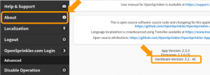
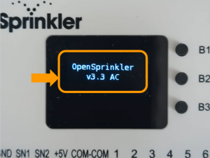
OpenSprinkler v3.2/3.3 wired Ethernet module, to allow wired Ethernet connection on your OpenSprinkler. Please select the correct module based on your OpenSprinkler’s hardware version. To check the hardware version, you can 1) at the controller’s homepage, swipe left to right to open the side menu, and click ‘About’, then note the Hardware Version displayed there; 2) alternatively, you can reboot your OpenSprinkler, during reboot it will briefly show hardware version on the LCD screen.
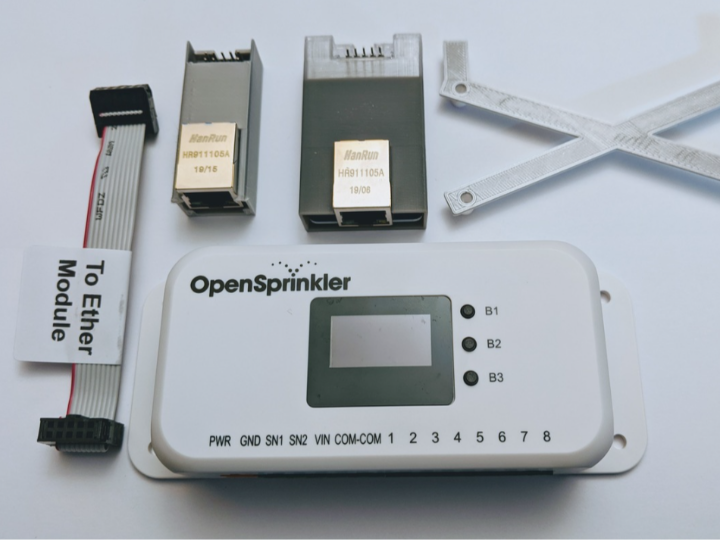
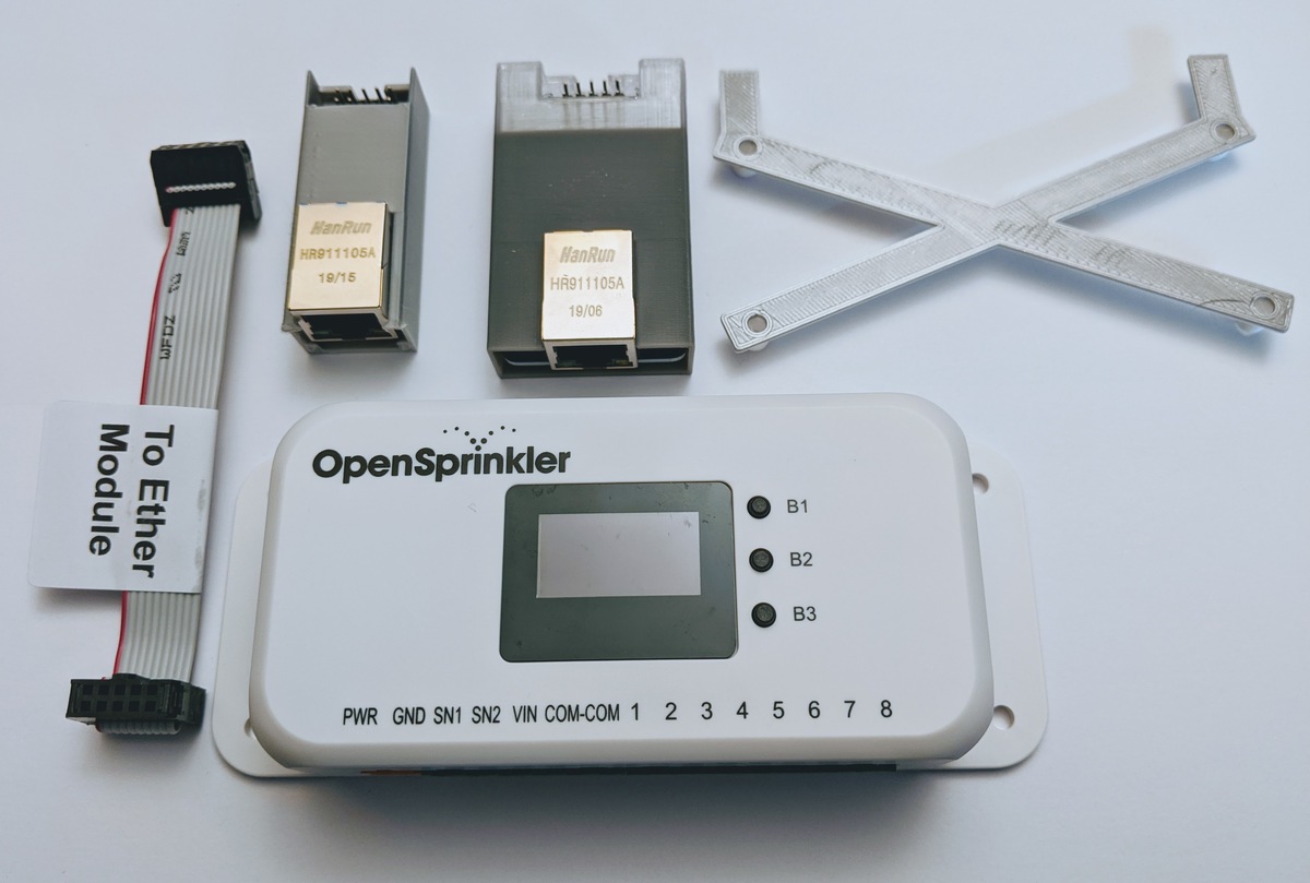
The Ethernet module package includes:
- One wired Ethernet module with 3D printed enclosure
- One ribbon cable
- One back bracket to help hold the screws in place when opening up the OpenSprinkler enclosure.
Instructions on how to install this module can be found here.
Install Wired Ethernet Module to OpenSprinkler v3.2 or 3.3
Wired Ethernet module is supported by OpenSprinkler v3.2 and v3.3. This is implemented by using an external Ethernet module. If you have OpenSprinkler v3.2 or v3.3 and you didn't purchase the wired Ethernet module, you can install it yourself. This page describes the installation instructions.
Step 1. If you didn't order a wired Ethernet module at the time of purchase, you can order it separately here: https://opensprinkler.com/product/wired_ethernet/. Please select the module based on your OpenSprinkler hardware version, as the two types of modules are NOT interchangeable. You will receive the Ethernet module in a 3D printed enclosure, a 2x5 ribbon cable, and a 3D printed bracket.
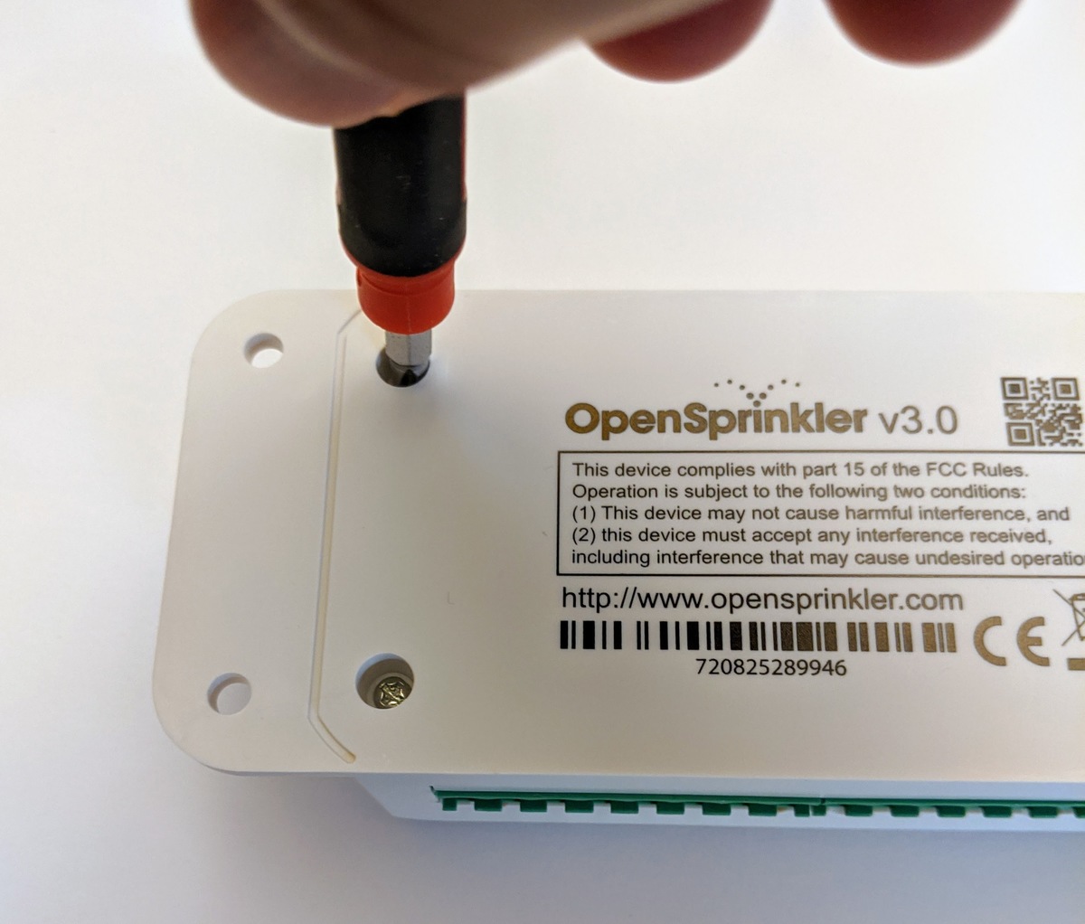
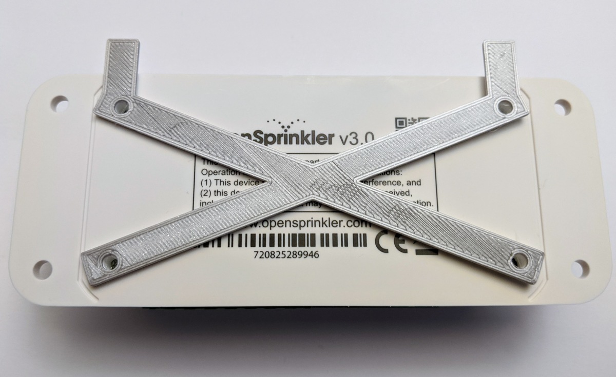
Step 2. Use a screwdriver to un-tighten the four screws at the back of the enclosure. Then insert the 3D printed back bracket to help hold the screws in place when you flip the controller upside down. (If you don't have the back bracket, just use a flat cardboard piece to cover the screws and flip the controller including the cardboard upside down so that the screws won't fall out)
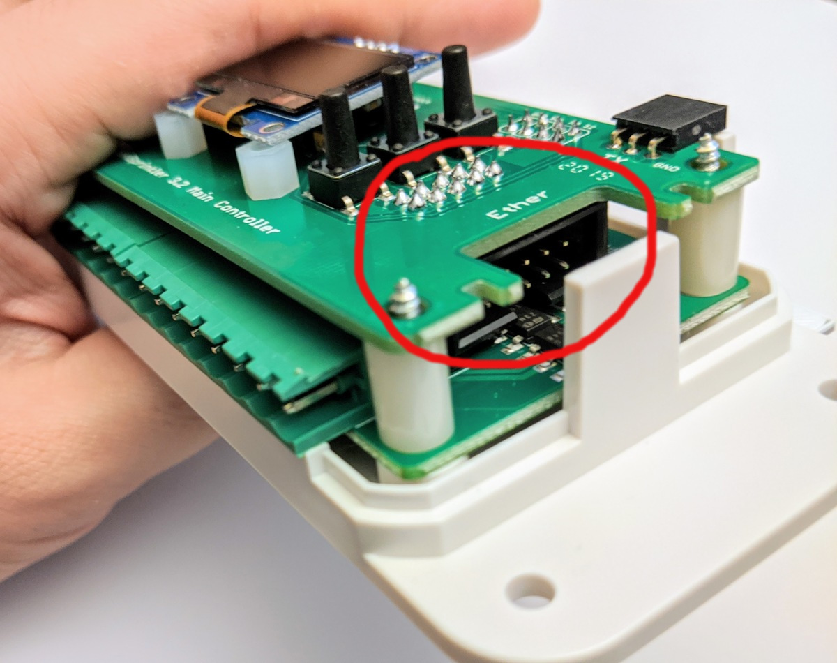
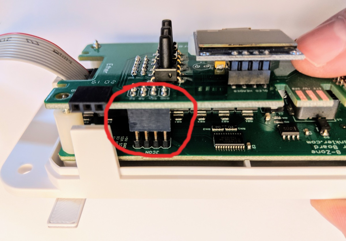
Step 3. Remove the top cover of the enclosure, double check that there is a 2x5 receptor under the top-level circuit board, as circled below. If you don't see this receptor, that means your controller is an earlier version than 3.2 and does NOT support wired Ethernet.
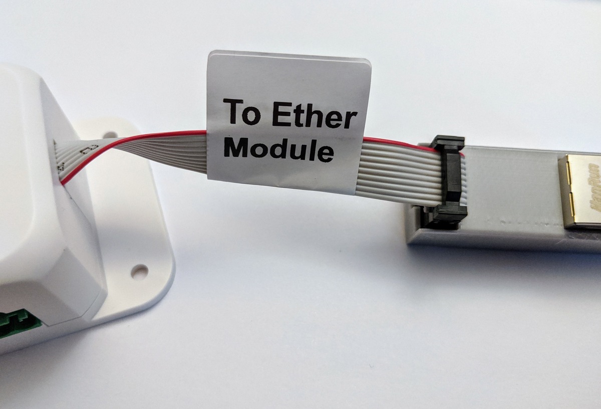
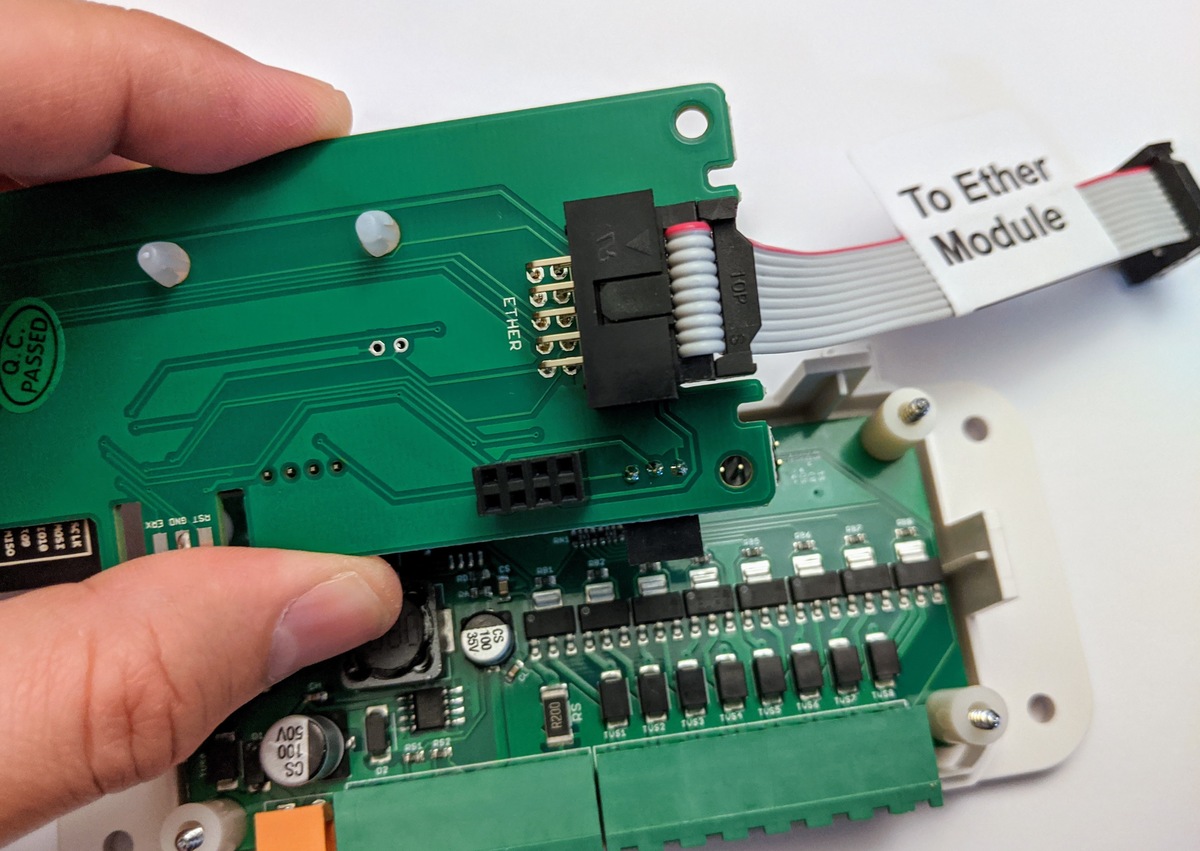
Next, separate the top-level circuit board from the bottom circuit board, and firmly insert the 2x5 ribbon cable into the receptor. Make sure the side that has a 'Ether Module' label remains on the outside, as in the picture shown below.
Step 4. Insert the top-level circuit board back to the bottom-level. Double check that the female pins on the top-level board aligns and matches the bottom-level, as circled below. Mis-alignment will cause the controller to malfunction!
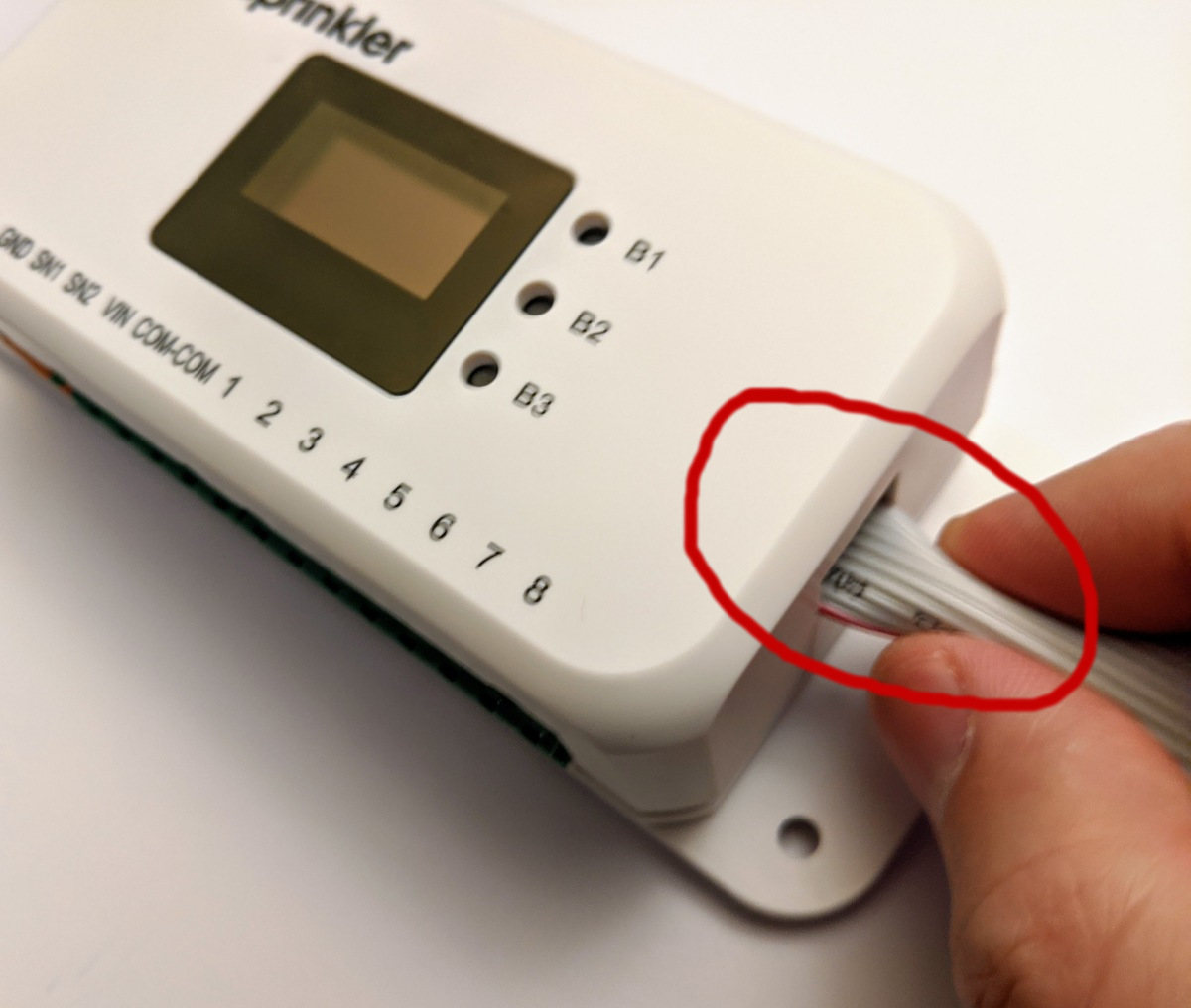
Step 5. Put the enclosure top cover back on. The 2x5 ribbon cable comes out from the hole on the right. Because the hole is slightly narrower than the cable width, you can lightly squeeze the cable (i.e. make an arc) to ensure the cable passes freely through the hole, as the picture below shows.
Step 6. With the back bracket (or cardboard piece) in place, flip the whole assembly upside down. Remove the back bracket (or cardboard piece), and tighten the screws at the back. Please DO NOT over-tighten the screws. Finally, insert the Ethernet module to the 2x5 ribbon cable. The cable connector is polarized so there is only one way to plug it in, as shown below.