
How to Build Factory Sensors with PP-W5500-POE on an MCU Platform?
PP-W5500-POE is a WIZnet W5500-based Ethernet and Power-over-Ethernet module for factory sensor nodes that need both wired data and local power from one LAN cab
How to Build Factory Sensors with PP-W5500-POE on an MCU Platform?
Summary
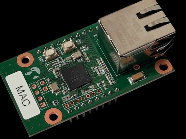
PP-W5500-POE is a WIZnet W5500-based Ethernet and Power-over-Ethernet module for factory sensor nodes that need both wired data and local power from one LAN cable. The W5500 provides the hardware TCP/IP Ethernet interface, SPI-based socket control, 10/100 Mbps PHY, and internal packet buffering, while the PoE section accepts IEEE 802.3af power and generates regulated 5 V and 3.3 V rails for the embedded device.
What the Project Does
This product is not a complete sensor node by itself. It is a network-and-power module intended to be integrated into an embedded system such as a temperature sensor, vibration monitor, counter input node, small gateway, or machine-status indicator.
In a typical factory sensor design, the MCU reads sensors through ADC, I2C, SPI, UART, GPIO, or pulse inputs. The MCU then communicates with the W5500 over SPI. The W5500 handles Ethernet transport and socket-level networking, while the PoE circuit receives power from a PoE switch or injector through the RJ45 cable and supplies local regulated outputs.
The practical result is a simpler field wiring model. One Ethernet cable carries both communication and power to the sensor enclosure. That reduces the need for a separate DC adapter, local power terminal, or extra cable run at each measurement point.
Where WIZnet Fits
The WIZnet product used here is the W5500. In PP-W5500-POE, W5500 is the Ethernet controller that gives the host MCU hardware-assisted TCP/IP networking over SPI.
The product page lists W5500 support for TCP, UDP, ICMP, IPv4, ARP, IGMP, and PPPoE, with eight independent hardware sockets and 32 KB of internal memory for TX/RX buffers. It also lists SPI mode 0 and mode 3 support, embedded 10/100 Ethernet PHY, auto-negotiation, full/half duplex operation, and 10/100Base-T compatibility.
For factory sensors, this matters because the MCU does not need to run a full software TCP/IP stack just to publish readings, receive configuration commands, or maintain a TCP/UDP service. The MCU can focus on sensor sampling, filtering, alarms, calibration, watchdog handling, and local protocol framing. W5500 handles socket-oriented Ethernet communication with fixed hardware resources.
The PoE section is equally important. PP-W5500-POE is listed as IEEE 802.3af compliant, supporting Mode A and Mode B, with a 40–60 V DC input range, over-voltage and over-current protection, a flyback PoE circuit using a DPA423 switching IC, 2 kVrms isolation, enhanced surge protection, and an operating temperature range of -45 °C to 85 °C. Its listed outputs are 5 V at 1.6 A and 3.3 V at 600 mA, with up to 8 W available.
Implementation Notes
The source is a product page, not a firmware repository. No application firmware or verified socket code is provided with the page, so the code below is not copied from the product source.
Conceptual integration example based on WIZnet ioLibrary:
uint8_t tx_size[8] = {2,2,2,2,2,2,2,2};
uint8_t rx_size[8] = {2,2,2,2,2,2,2,2};

wizchip_init(tx_size, rx_size);

wiz_NetInfo netinfo = {
    .mac = {0x00, 0x08, 0xDC, 0x12, 0x34, 0x56},
    .ip  = {192, 168, 10, 50},
    .sn  = {255, 255, 255, 0},
    .gw  = {192, 168, 10, 1},
    .dns = {192, 168, 10, 1},
    .dhcp = NETINFO_STATIC
};

wizchip_setnetinfo(&netinfo);
This initialization exists to make the W5500 a predictable network endpoint on the factory LAN. Static IP addressing is common in machine networks where maintenance staff need to know which sensor node belongs to which asset. DHCP can also be used, but the factory network should then reserve addresses by MAC address.
Conceptual integration example based on WIZnet ioLibrary:
#define SOCK_SENSOR_TCP  0
#define SERVER_PORT      5020

uint8_t server_ip[4] = {192, 168, 10, 100};
uint8_t payload[] = "machine=press_01,temp=42.6,vib=0.18\r\n";

socket(SOCK_SENSOR_TCP, Sn_MR_TCP, 40000, 0);

if (connect(SOCK_SENSOR_TCP, server_ip, SERVER_PORT) == SOCK_OK) {
    send(SOCK_SENSOR_TCP, payload, sizeof(payload) - 1);
}

disconnect(SOCK_SENSOR_TCP);
close(SOCK_SENSOR_TCP);
This socket flow represents a simple factory sensor upload. The MCU reads local sensor values, formats a compact payload, opens a W5500 TCP socket, sends the data to a local collector or gateway, and closes the connection. A production design would normally add reconnect handling, retry limits, link-state checks, persistent error counters, and watchdog-safe timing.
For the hardware side, the module should be treated as both a network interface and a power subsystem. The RJ45 side receives PoE from a compliant switch or injector. The regulated 5 V and 3.3 V outputs can power the MCU and low-power sensor electronics, but the designer must verify the complete current budget, inrush behavior, sensor load, enclosure temperature, and any isolated/non-isolated ground boundaries before using those rails in a field product.
Practical Tips / Pitfalls
- Confirm the PoE source is IEEE 802.3af compliant. Passive PoE injectors and non-standard supplies can damage equipment or bypass expected protection behavior.
- Budget power from the listed 8 W output limit, not from the theoretical PoE cable power. Include MCU, sensors, LEDs, relays, signal conditioners, and startup current.
- Keep the SPI wiring short and controlled. W5500 uses SPI for host communication, so noisy or long internal wiring can create network symptoms that are actually board-level signal-integrity problems.
- Use link and socket status in firmware. A factory node should distinguish cable unplugged, switch down, server unreachable, and application timeout.
- Protect field I/O separately. PoE isolation and surge protection help the Ethernet/power side, but sensor inputs connected to machines may still need their own isolation, filtering, TVS protection, or optocouplers.
- Plan IP addressing before deployment. Static IPs are easy to service, while DHCP reservations scale better when many sensors are installed.
- Treat Telnet-style or plain TCP debug ports as maintenance-only. Factory networks still need segmentation, authentication at the application layer, or restricted access paths.
FAQ
Q: Why use PP-W5500-POE for factory sensors?
A: It combines W5500 wired Ethernet with an IEEE 802.3af PoE power section, so a sensor node can receive both communication and power over one cable. That is useful in factories where sensor points may be far from convenient DC power but already have structured Ethernet wiring.
Q: How does PP-W5500-POE connect to an MCU platform?
A: The MCU connects to W5500 through SPI using SCK, MOSI, MISO, chip-select, reset, power, and ground. The MCU firmware registers SPI read/write routines, initializes W5500 network parameters, then uses sockets for TCP or UDP communication.
Q: What role does W5500 play in this factory sensor design?
A: W5500 is the Ethernet transport and socket engine. The MCU handles sensor sampling and application logic, while W5500 handles TCP/UDP socket communication, Ethernet PHY operation, TX/RX buffering, and hardware-assisted network protocols.
Q: Can beginners follow this design?
A: Yes for a lab prototype, but a field-ready PoE sensor requires more care. Developers should understand SPI, TCP/UDP sockets, IP addressing, PoE power budgeting, grounding, surge protection, and watchdog recovery before installing it in a factory environment.
Q: How does PoE Ethernet compare with separate DC power?
A: PoE Ethernet reduces cabling by carrying power and data on one LAN cable, which simplifies installation and maintenance for distributed sensors. Separate DC power can be simpler on a bench and may support larger loads, but it adds another cable, another failure point, and more installation work at each sensor location.
Source
Original product page: PLATYPUS PP-W5500-POE. The accessible indexed product page identifies the module as a W5500-based PoE Ethernet module with IEEE 802.3af Mode A/B support, 40–60 V input, 5 V and 3.3 V outputs, 8 W output capability, 2 kVrms isolation, surge protection, and W5500 hardware TCP/IP Ethernet features.
Supporting source: PLATYPUS Qiita article introducing PP-W5500-POE as a W5500-based compact Ethernet module with IEEE 802.3af PoE, 8 W power capability, W5500 socket support, 32 KB buffer memory, and SPI mode 0/3 interface.
License: Not clearly stated on the product page.
Tags
#PPW5500POE #W5500 #WIZnet #PoE #Ethernet #FactorySensors #IndustrialIoT #SPI #EmbeddedFirmware #TCPIP #SocketProgramming #PowerOverEthernet
MCU 플랫폼에서 PP-W5500-POE로 공장 센서를 구축하는 방법은?
Summary
PP-W5500-POE는 공장 센서 노드가 하나의 LAN 케이블로 유선 데이터와 로컬 전원을 동시에 받아야 할 때 사용할 수 있는 WIZnet W5500 기반 Ethernet 및 Power-over-Ethernet 모듈입니다. W5500은 hardware TCP/IP Ethernet interface, SPI 기반 socket control, 10/100 Mbps PHY, internal packet buffering을 제공하고, PoE 회로는 IEEE 802.3af 전원을 입력받아 embedded device용 5 V 및 3.3 V 전원을 생성합니다.
What the Project Does
이 제품은 완성된 센서 노드가 아니라 embedded system에 통합하기 위한 network-and-power module입니다. 예를 들어 온도 센서, 진동 모니터, 카운터 입력 노드, 소형 게이트웨이, 장비 상태 표시 장치에 사용할 수 있습니다.
일반적인 공장 센서 설계에서 MCU는 ADC, I2C, SPI, UART, GPIO, pulse input 등을 통해 센서를 읽습니다. MCU는 이후 SPI를 통해 W5500과 통신합니다. W5500은 Ethernet transport와 socket-level networking을 처리하고, PoE 회로는 PoE switch 또는 injector에서 RJ45 케이블을 통해 전원을 받아 로컬 regulated output을 제공합니다.
실용적인 결과는 현장 배선이 단순해진다는 점입니다. 하나의 Ethernet 케이블이 sensor enclosure까지 통신과 전원을 함께 전달합니다. 따라서 각 측정 지점마다 별도의 DC adapter, local power terminal, 추가 cable run을 배치해야 하는 부담이 줄어듭니다.
Where WIZnet Fits
이 제품에서 사용되는 WIZnet 제품은 W5500입니다. PP-W5500-POE에서 W5500은 host MCU에 SPI 기반 hardware-assisted TCP/IP networking을 제공하는 Ethernet controller입니다.
제품 정보에 따르면 W5500은 TCP, UDP, ICMP, IPv4, ARP, IGMP, PPPoE를 지원하고, 8개의 independent hardware sockets와 32 KB internal memory for TX/RX buffers를 제공합니다. 또한 SPI mode 0 및 mode 3, embedded 10/100 Ethernet PHY, auto-negotiation, full/half duplex operation, 10/100Base-T compatibility를 지원합니다.
공장 센서에서는 이 점이 중요합니다. MCU가 단순히 측정값을 전송하거나, 설정 명령을 수신하거나, TCP/UDP 서비스를 유지하기 위해 전체 software TCP/IP stack을 실행할 필요가 줄어듭니다. MCU는 sensor sampling, filtering, alarm, calibration, watchdog handling, local protocol framing에 집중하고, W5500은 고정된 hardware resource로 socket-oriented Ethernet communication을 처리합니다.
PoE 회로도 같은 비중으로 중요합니다. PP-W5500-POE는 IEEE 802.3af compliant module로 소개되며, Mode A와 Mode B, 40–60 V DC input range, over-voltage 및 over-current protection, DPA423 switching IC 기반 flyback PoE circuit, 2 kVrms isolation, surge protection, -45 °C to 85 °C operating temperature range가 제시되어 있습니다. 출력은 5 V 1.6 A 및 3.3 V 600 mA이며, 최대 8 W output을 제공합니다.
Implementation Notes
원본은 제품 페이지이며 firmware repository가 아닙니다. 따라서 제품 페이지에서 검증된 application firmware나 socket code는 제공되지 않습니다. 아래 코드는 제품 소스에서 복사한 것이 아닙니다.
Conceptual integration example based on WIZnet ioLibrary:
uint8_t tx_size[8] = {2,2,2,2,2,2,2,2};
uint8_t rx_size[8] = {2,2,2,2,2,2,2,2};

wizchip_init(tx_size, rx_size);

wiz_NetInfo netinfo = {
    .mac = {0x00, 0x08, 0xDC, 0x12, 0x34, 0x56},
    .ip  = {192, 168, 10, 50},
    .sn  = {255, 255, 255, 0},
    .gw  = {192, 168, 10, 1},
    .dns = {192, 168, 10, 1},
    .dhcp = NETINFO_STATIC
};

wizchip_setnetinfo(&netinfo);
이 초기화는 W5500을 공장 LAN에서 예측 가능한 network endpoint로 만들기 위해 사용됩니다. Static IP addressing은 유지보수 담당자가 어떤 sensor node가 어떤 asset에 연결되어 있는지 알아야 하는 machine network에서 흔히 사용됩니다. DHCP도 사용할 수 있지만, 이 경우 factory network에서 MAC address 기준의 DHCP reservation을 설정하는 편이 좋습니다.
Conceptual integration example based on WIZnet ioLibrary:
#define SOCK_SENSOR_TCP  0
#define SERVER_PORT      5020

uint8_t server_ip[4] = {192, 168, 10, 100};
uint8_t payload[] = "machine=press_01,temp=42.6,vib=0.18\r\n";

socket(SOCK_SENSOR_TCP, Sn_MR_TCP, 40000, 0);

if (connect(SOCK_SENSOR_TCP, server_ip, SERVER_PORT) == SOCK_OK) {
    send(SOCK_SENSOR_TCP, payload, sizeof(payload) - 1);
}

disconnect(SOCK_SENSOR_TCP);
close(SOCK_SENSOR_TCP);
이 socket flow는 단순한 factory sensor upload를 나타냅니다. MCU는 local sensor value를 읽고 compact payload로 formatting한 뒤, W5500 TCP socket을 열고 local collector 또는 gateway로 데이터를 전송한 다음 connection을 닫습니다. 실제 제품 설계에서는 reconnect handling, retry limit, link-state check, persistent error counter, watchdog-safe timing을 추가해야 합니다.
Hardware 측면에서는 이 모듈을 network interface이자 power subsystem으로 다뤄야 합니다. RJ45 쪽은 compliant PoE switch 또는 injector에서 전원을 받습니다. Regulated 5 V와 3.3 V output은 MCU와 저전력 sensor electronics에 사용할 수 있지만, field product에 적용하기 전에는 전체 current budget, inrush behavior, sensor load, enclosure temperature, isolated/non-isolated ground boundary를 반드시 검증해야 합니다.
Practical Tips / Pitfalls
- PoE source가 IEEE 802.3af compliant인지 확인해야 합니다. Passive PoE injector나 비표준 전원은 장비를 손상시키거나 보호 동작을 우회할 수 있습니다.
- 이론적인 PoE cable power가 아니라 listed 8 W output limit을 기준으로 power budget을 계산해야 합니다. MCU, sensors, LEDs, relays, signal conditioners, startup current를 모두 포함해야 합니다.
- SPI wiring은 짧고 안정적으로 구성해야 합니다. W5500은 host communication에 SPI를 사용하므로, noisy하거나 긴 내부 배선은 실제로는 board-level signal-integrity 문제인데 network symptom처럼 보일 수 있습니다.
- Firmware에서 link status와 socket status를 사용해야 합니다. Factory node는 cable unplugged, switch down, server unreachable, application timeout을 구분할 수 있어야 합니다.
- Field I/O는 별도로 보호해야 합니다. PoE isolation과 surge protection은 Ethernet/power side에 도움이 되지만, machine에 연결되는 sensor input은 별도의 isolation, filtering, TVS protection, optocoupler가 필요할 수 있습니다.
- 배포 전에 IP addressing 계획을 세워야 합니다. Static IP는 service가 쉽고, DHCP reservation은 센서 수가 많을 때 확장성이 좋습니다.
- Telnet-style 또는 plain TCP debug port는 maintenance-only로 다뤄야 합니다. Factory network에서도 segmentation, application-layer authentication, restricted access path가 필요합니다.
FAQ
Q: 공장 센서에 PP-W5500-POE를 사용하는 이유는 무엇인가요?
A: 이 모듈은 W5500 wired Ethernet과 IEEE 802.3af PoE power section을 결합하므로, sensor node가 하나의 케이블로 통신과 전원을 동시에 받을 수 있습니다. 공장에서는 센서 지점이 편리한 DC power 위치에서 멀리 떨어져 있지만 structured Ethernet wiring은 확보된 경우가 많아 유용합니다.
Q: PP-W5500-POE는 MCU platform에 어떻게 연결되나요?
A: MCU는 SCK, MOSI, MISO, chip-select, reset, power, ground를 사용해 W5500과 SPI로 연결됩니다. MCU firmware는 SPI read/write routine을 등록하고, W5500 network parameter를 초기화한 다음 TCP 또는 UDP socket을 사용해 통신합니다.
Q: 이 공장 센서 설계에서 W5500은 어떤 역할을 하나요?
A: W5500은 Ethernet transport와 socket engine입니다. MCU는 sensor sampling과 application logic을 처리하고, W5500은 TCP/UDP socket communication, Ethernet PHY operation, TX/RX buffering, hardware-assisted network protocol을 담당합니다.
Q: 초보자도 이 설계를 따라할 수 있나요?
A: Lab prototype 수준에서는 가능합니다. 하지만 field-ready PoE sensor를 만들려면 SPI, TCP/UDP sockets, IP addressing, PoE power budgeting, grounding, surge protection, watchdog recovery를 이해해야 합니다.
Q: PoE Ethernet은 separate DC power와 어떻게 다른가요?
A: PoE Ethernet은 하나의 LAN cable로 power와 data를 함께 전달하므로 distributed sensor의 설치와 유지보수가 단순해집니다. Separate DC power는 bench test에서는 더 단순하고 큰 부하를 지원하기 쉬울 수 있지만, 각 sensor location마다 추가 cable, 추가 failure point, 추가 설치 작업이 필요합니다.
Source
Original product page: PLATYPUS PP-W5500-POE. 접근 가능한 indexed product information은 이 모듈을 IEEE 802.3af Mode A/B, 40–60 V input, 5 V 및 3.3 V outputs, 8 W output capability, 2 kVrms isolation, surge protection, W5500 hardware TCP/IP Ethernet features를 갖춘 W5500 기반 PoE Ethernet module로 설명합니다.
Supporting source: PLATYPUS Qiita article introducing PP-W5500-POE as a W5500-based compact Ethernet module with IEEE 802.3af PoE, 8 W power capability, W5500 socket support, 32 KB buffer memory, and SPI mode 0/3 interface.
License: 제품 페이지에서 명확히 확인되지 않았습니다.
Tags
#PPW5500POE #W5500 #WIZnet #PoE #Ethernet #FactorySensors #IndustrialIoT #SPI #EmbeddedFirmware #TCPIP #SocketProgramming #PowerOverEthernet