



How to Add PoE Ethernet with WIZnet W5500 on PP-W5500-POE?
PP-W5500-POE is a compact Ethernet-and-power module for Industrial IoT and commercial embedded devices that need wired networking and power delivery through one
How to Add PoE Ethernet with WIZnet W5500 on PP-W5500-POE?
Summary
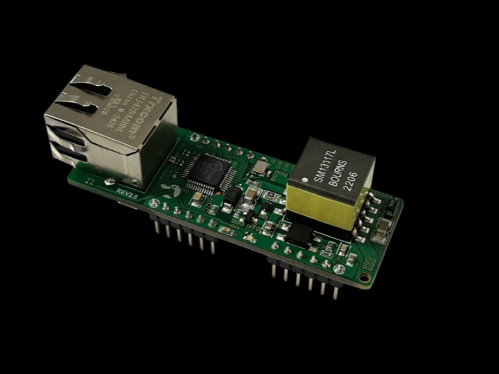
PP-W5500-POE is a compact Ethernet-and-power module for Industrial IoT and commercial embedded devices that need wired networking and power delivery through one LAN cable. The board uses WIZnet W5500 as the Ethernet controller and hardware TCP/IP engine, while the PoE section supplies up to 8 W with 5 V and 3.3 V outputs for the host system or nearby circuitry.
What the Project Does
PP-W5500-POE combines a WIZnet W5500 Ethernet interface with a PoE power front end. The product page describes it as a board that provides Ethernet plus a separate power supply, with PoE module support and up to 8 W output capability.
The practical architecture is straightforward: a host MCU connects to the W5500 side through SPI, while the LAN cable provides both network connectivity and PoE input power. The PoE block accepts 40–60 V DC input, supports IEEE 802.3af, works with Mode A and Mode B power sourcing, and generates 5 V at 1.6 A plus a 3.3 V LDO output rated at 600 mA.
For Industrial IoT and commercial products, this board targets devices where separate Ethernet and power wiring would increase installation cost or failure points. Typical fit areas include smart sensors, small gateways, monitoring nodes, service interfaces, and control panels that benefit from wired Ethernet plus centralized PoE power.
Where WIZnet Fits
The exact WIZnet product is W5500. In PP-W5500-POE, W5500 is the network controller: it provides the Ethernet MAC/PHY, hardwired TCP/IP stack, socket engine, and internal packet buffers. The host MCU does not need to run the full TCP/IP stack in software; it can access W5500 over SPI and use socket-level communication for TCP, UDP, ICMP, IPv4, ARP, IGMP, and PPPoE.
The hardware performance points matter here. W5500 supports SPI mode 0 and 3, 8 independent sockets, 32 KB internal Tx/Rx buffer memory, embedded 10/100 Ethernet PHY, auto negotiation, full/half duplex, and 10/100-based Ethernet operation. WIZnet’s own product page also states SPI operation up to 80 MHz and network performance up to 55 Mbps.
For a PoE node, the W5500 reduces firmware and RAM pressure on the host MCU, while the PoE section reduces field wiring. That combination is useful when the device must be mounted in a cabinet, ceiling, wall, machine frame, or remote sensor position where one cable is easier to install and maintain than separate power and data cables.
Implementation Notes
The source is a hardware product page, not a firmware repository, so there is no project-specific source code to quote. The verified implementation detail is the board-level architecture.
A typical integration uses four SPI signals between the host MCU and W5500: SCK, MOSI, MISO, and chip select. In addition, a practical design should expose or route W5500 reset and interrupt signals so the MCU can recover the Ethernet controller and avoid constant polling. The PP-W5500-POE product page also lists status-oriented hardware functions such as built-in RJ45, built-in LDO, auto negotiation, 10/100 operation, full/half duplex, and embedded Ethernet PHY support.
Power integration should be treated as part of the network design, not as an afterthought. The module’s PoE block supports 40–60 V input, 5 V output at 1.6 A, 3.3 V LDO output at 600 mA, 8 W output, 400 kHz fixed switching frequency, 2 kVrms isolation, overvoltage protection, overcurrent protection, enhanced surge protection, and internal two-channel bridge rectifiers.
For firmware, the host MCU should initialize SPI, reset W5500, confirm register access, configure MAC/IP/DHCP or static settings, allocate socket buffers, and then run the application protocol. In a commercial product, the firmware should also monitor PHY link state, socket state, PoE power stability, watchdog recovery, and reconnect behavior after cable removal or switch restart.
Practical Tips / Pitfalls
- Budget the 8 W output carefully. The module can supply the Ethernet controller plus external circuitry, but motors, relays, displays, radios, and sensors must be included in the thermal and current budget.
- Use the reset and interrupt pins, not only SPI. Reset helps recover from abnormal link or firmware states, and interrupt-driven handling can reduce MCU polling load.
- Keep PoE and signal layout disciplined. The product includes isolation and surge protection, but the carrier board still needs proper grounding, creepage, clearance, and noise-aware routing.
- Validate link negotiation in the target switch environment. W5500 supports 10/100 operation, auto negotiation, and full/half duplex, but field switches and cable quality still affect link behavior.
- Separate application buffering from W5500 buffering. W5500 has 32 KB internal Tx/Rx buffer memory, but the host MCU still needs safe buffers for protocol frames and command parsing.
- Test brownout, cable removal, and PoE PSE restart. Industrial installations often fail in power-transition conditions before they fail in steady-state operation.
FAQ
Q: Why use WIZnet W5500 on PP-W5500-POE?
A: W5500 provides a hardwired TCP/IP stack, embedded 10/100 Ethernet MAC/PHY, 8 sockets, and 32 KB internal buffer memory. On a PoE module, this lets a small host MCU handle application logic while W5500 handles Ethernet transport and socket buffering.
Q: How does W5500 connect to the host platform?
A: The host MCU connects to W5500 over SPI, using SPI mode 0 or 3. A robust hardware design should also connect chip select, reset, and interrupt, while the board’s RJ45 and PoE circuit handle the Ethernet cable side.
Q: What role does W5500 play in this PoE module?
A: W5500 is the Ethernet and TCP/IP engine. The PoE section brings power from the LAN cable and generates board-level rails, while W5500 provides the network interface, socket resources, protocol offload, and packet buffers used by the MCU application.
Q: Can beginners use this board?
A: Yes, if they already understand SPI wiring, basic IPv4 configuration, and MCU firmware bring-up. The board removes much of the Ethernet magnetics and PoE power-design burden, but the user still needs to write or port W5500 firmware logic for DHCP/static IP, sockets, reconnect handling, and application protocol behavior.
Q: How does W5500 compare with ENC28J60 for this use case?
A: W5500 includes a hardwired TCP/IP stack, 8 sockets, 32 KB Tx/Rx buffer memory, and 10/100 Ethernet PHY support. ENC28J60 is also an SPI Ethernet controller, but Microchip describes it as a 10BASE-T stand-alone Ethernet controller; distributor and datasheet summaries list 8 KB buffer RAM, so the host MCU typically carries more network-stack responsibility when using ENC28J60.
Source
Original product page: PLATYPUS, PP-W5500-POE. License is not stated on the product page.
WIZnet product reference: W5500 Ethernet Controller.
Alternative reference for comparison: Microchip ENC28J60 datasheet/product information.
Tags
#W5500 #WIZnet #PPW5500POE #PoE #Ethernet #SPI #IndustrialIoT #Commercial #HardwareWiring #Performance #TCPIP #ENC28J60
PP-W5500-POE에서 WIZnet W5500으로 PoE 이더넷을 추가하는 방법은?
요약
PP-W5500-POE는 하나의 LAN 케이블로 유선 네트워크와 전원을 함께 제공해야 하는 Industrial IoT 및 상용 임베디드 장치용 소형 Ethernet + PoE 모듈입니다. 이 보드는 WIZnet W5500을 이더넷 컨트롤러와 하드웨어 TCP/IP 엔진으로 사용하며, PoE 전원부는 최대 8 W 출력과 5 V 및 3.3 V 전원을 제공해 호스트 시스템이나 주변 회로에 전원을 공급합니다.
프로젝트가 하는 일
PP-W5500-POE는 WIZnet W5500 이더넷 인터페이스와 PoE 전원 회로를 하나의 보드에 결합한 제품입니다. 제품 페이지에서는 이 보드를 Ethernet과 별도 전원 출력을 제공하는 보드로 설명하며, PoE 모듈 지원과 최대 8 W 출력 기능을 명시합니다.
실제 아키텍처는 단순합니다. 호스트 MCU는 SPI로 W5500에 연결되고, LAN 케이블은 네트워크 연결과 PoE 입력 전원을 동시에 제공합니다. PoE 블록은 40–60 V DC 입력을 받고, IEEE 802.3af를 지원하며, Mode A와 Mode B 전원 공급 방식을 모두 지원합니다. 출력은 5 V 1.6 A와 3.3 V LDO 600 mA입니다.
Industrial IoT 및 상용 제품에서는 이 구조가 설치 비용과 고장 지점을 줄이는 데 유용합니다. 별도의 전원선과 이더넷 케이블을 따로 배선해야 하는 장치보다, 하나의 LAN 케이블만 필요한 구조가 현장 설치와 유지보수에 유리합니다. 적용 예로는 스마트 센서, 소형 게이트웨이, 모니터링 노드, 서비스 인터페이스, 제어 패널 등이 있습니다.
WIZnet이 들어가는 위치
이 프로젝트에서 사용되는 WIZnet 제품은 W5500입니다. PP-W5500-POE에서 W5500은 네트워크 컨트롤러 역할을 합니다. Ethernet MAC/PHY, 하드웨어 TCP/IP 스택, 소켓 엔진, 내부 패킷 버퍼를 제공합니다. 호스트 MCU는 전체 TCP/IP 스택을 소프트웨어로 직접 구현할 필요 없이 SPI로 W5500에 접근하고, TCP, UDP, ICMP, IPv4, ARP, IGMP, PPPoE 같은 소켓 기반 통신을 사용할 수 있습니다.
하드웨어 성능 측면에서도 W5500은 이 보드의 핵심입니다. W5500은 SPI mode 0과 mode 3을 지원하고, 8개 독립 소켓, 32 KB 내부 Tx/Rx 버퍼 메모리, 내장 10/100 Ethernet PHY, auto negotiation, full/half duplex, 10/100 기반 이더넷 동작을 제공합니다. WIZnet 제품 정보 기준으로 SPI는 최대 80 MHz까지 동작하며, 네트워크 성능은 최대 55 Mbps 수준으로 제시됩니다.
PoE 노드에서 W5500은 호스트 MCU의 펌웨어와 RAM 부담을 줄이고, PoE 회로는 현장 배선을 줄입니다. 이 조합은 캐비닛, 천장, 벽면, 장비 프레임, 원격 센서 위치처럼 전원선과 데이터선을 따로 설치하기 어려운 환경에서 특히 유용합니다.
구현 참고 사항
이 소스는 펌웨어 저장소가 아니라 하드웨어 제품 페이지이므로, 프로젝트별 소스 코드는 확인할 수 없습니다. 검증 가능한 구현 정보는 보드 수준의 아키텍처입니다.
일반적인 통합 구조에서는 호스트 MCU와 W5500 사이에 네 개의 SPI 신호가 사용됩니다. SCK, MOSI, MISO, chip select입니다. 실제 제품 설계에서는 W5500 reset과 interrupt 신호도 MCU에 연결하는 것이 좋습니다. reset은 비정상 상태 복구에 필요하고, interrupt는 지속적인 polling 없이 소켓 이벤트를 처리하는 데 도움이 됩니다.
PP-W5500-POE 제품 페이지는 내장 RJ45, 내장 LDO, auto negotiation, 10/100 동작, full/half duplex, 내장 Ethernet PHY 같은 하드웨어 기능도 명시합니다.
전원 통합은 네트워크 설계의 일부로 봐야 합니다. 이 모듈의 PoE 블록은 40–60 V 입력, 5 V 1.6 A 출력, 3.3 V LDO 600 mA 출력, 8 W 출력, 400 kHz 고정 스위칭 주파수, 2 kVrms 절연, 과전압 보호, 과전류 보호, 향상된 서지 보호, 내부 2채널 브리지 정류기를 제공합니다.
펌웨어 관점에서는 호스트 MCU가 SPI를 초기화하고, W5500을 리셋한 뒤, 레지스터 접근을 확인해야 합니다. 이후 MAC/IP/DHCP 또는 static IP 설정, 소켓 버퍼 할당, 애플리케이션 프로토콜 실행 순서로 진행합니다. 상용 제품에서는 PHY 링크 상태, 소켓 상태, PoE 전원 안정성, watchdog 복구, 케이블 제거 또는 스위치 재시작 이후의 재연결 동작도 함께 관리해야 합니다.
실무 팁 / 주의점
- 8 W 출력 예산을 신중히 계산해야 합니다. 모듈이 이더넷 컨트롤러와 외부 회로에 전원을 공급할 수 있지만, 모터, 릴레이, 디스플레이, 무선 모듈, 센서까지 포함해 열과 전류 예산을 검토해야 합니다.
- SPI만 연결하지 말고 reset과 interrupt 핀도 사용하는 것이 좋습니다. reset은 비정상 링크나 펌웨어 상태에서 복구를 돕고, interrupt 기반 처리는 MCU polling 부하를 줄일 수 있습니다.
- PoE와 신호 레이아웃을 분리해 설계해야 합니다. 제품이 절연과 서지 보호를 포함하더라도, 캐리어 보드에서는 접지, creepage, clearance, 노이즈 경로를 신중히 다뤄야 합니다.
- 실제 스위치 환경에서 링크 negotiation을 검증해야 합니다. W5500은 10/100 동작, auto negotiation, full/half duplex를 지원하지만, 현장 스위치와 케이블 품질에 따라 링크 동작이 달라질 수 있습니다.
- W5500 내부 버퍼와 애플리케이션 버퍼를 구분해야 합니다. W5500에는 32 KB 내부 Tx/Rx 버퍼가 있지만, 호스트 MCU에도 프로토콜 프레임과 명령 파싱을 위한 안전한 버퍼가 필요합니다.
- brownout, 케이블 제거, PoE PSE 재시작을 테스트해야 합니다. 산업 현장에서는 정상 상태보다 전원 전환 조건에서 문제가 먼저 드러나는 경우가 많습니다.
FAQ
Q: PP-W5500-POE에서 왜 WIZnet W5500을 사용하나요?
A: W5500은 하드웨어 TCP/IP 스택, 내장 10/100 Ethernet MAC/PHY, 8개 소켓, 32 KB 내부 버퍼 메모리를 제공합니다. PoE 모듈에서 이 구조는 작은 호스트 MCU가 애플리케이션 로직에 집중하고, W5500이 이더넷 전송과 소켓 버퍼링을 담당하게 합니다.
Q: W5500은 호스트 플랫폼에 어떻게 연결하나요?
A: 호스트 MCU는 SPI로 W5500에 연결합니다. W5500은 SPI mode 0 또는 mode 3을 지원합니다. 견고한 하드웨어 설계에서는 chip select, reset, interrupt도 함께 연결해야 하며, 보드의 RJ45와 PoE 회로가 이더넷 케이블 측을 담당합니다.
Q: 이 PoE 모듈에서 W5500은 어떤 역할을 하나요?
A: W5500은 이더넷 및 TCP/IP 엔진입니다. PoE 회로는 LAN 케이블에서 전원을 받아 보드 전원 레일을 만들고, W5500은 MCU 애플리케이션이 사용하는 네트워크 인터페이스, 소켓 자원, 프로토콜 오프로딩, 패킷 버퍼를 제공합니다.
Q: 초보자도 이 보드를 사용할 수 있나요?
A: SPI 배선, 기본 IPv4 설정, MCU 펌웨어 bring-up을 이해하고 있다면 사용할 수 있습니다. 이 보드는 이더넷 magnetics와 PoE 전원 설계 부담을 줄여주지만, 사용자는 여전히 DHCP/static IP, 소켓 처리, 재연결 처리, 애플리케이션 프로토콜 동작을 위한 W5500 펌웨어를 작성하거나 포팅해야 합니다.
Q: 이 용도에서 W5500은 ENC28J60과 어떻게 다른가요?
A: W5500은 하드웨어 TCP/IP 스택, 8개 소켓, 32 KB Tx/Rx 버퍼 메모리, 10/100 Ethernet PHY를 포함합니다. ENC28J60도 SPI 이더넷 컨트롤러이지만, 10BASE-T 독립형 이더넷 컨트롤러로 분류되며 버퍼 RAM은 8 KB 수준입니다. 따라서 ENC28J60을 사용할 경우 호스트 MCU가 네트워크 스택 책임을 더 많이 부담하는 구조가 됩니다.
출처
Original product page: PLATYPUS, PP-W5500-POE. 제품 페이지에 라이선스는 명시되어 있지 않습니다.
https://www.us-platypus.com/56/?idx=45
WIZnet product reference: W5500 Ethernet Controller.
https://wiznet.io/products/ethernet-chips/w5500
Alternative reference for comparison: Microchip ENC28J60 datasheet/product information.
https://ww1.microchip.com/downloads/en/DeviceDoc/39662e.pdf
태그
#W5500 #WIZnet #PPW5500POE #PoE #Ethernet #SPI #IndustrialIoT #Commercial #HardwareWiring #Performance #TCPIP #ENC28J60