
DK60-STM32F412RE
DK60-STM32F412RE

WIZnet - W5500
x 1
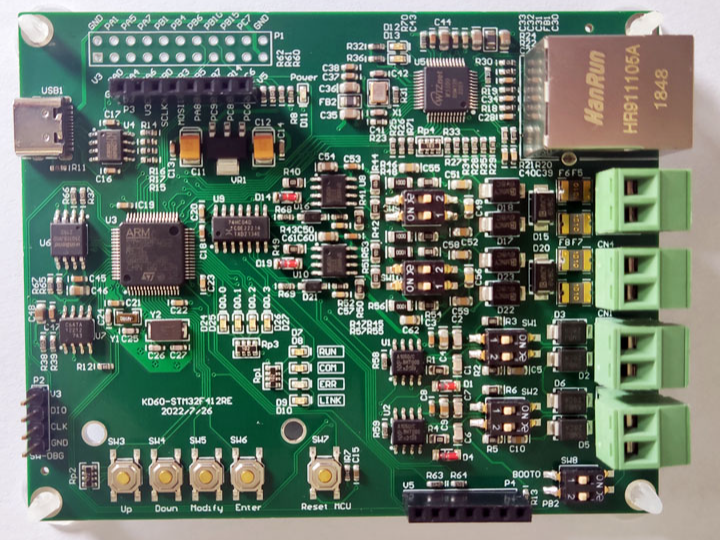
Development board introduction
The main functions of the development board DK60-STM32F412RE are:
- 1 USB to TTL serial port (CH340N).
- 2-way RS485.
- 2-way CAN.
- 1 Ethernet, implemented using W5500.
- 4 running indicators (RUN/COM/ERR/LINK).
- 4 input buttons.
- 4 output indicators.
- 1 ferroelectric memory chip MB85RC64.
- 1 FLASH memory chip W25Q128.
- OLD display, SSD1306 (optional).
- 4G-CAT1 module, FS-MCore-E600NLA (optional).
Based on the development board DK60-STM32F412RE, the following function demonstrations can be completed:
- PLC system programming and monitoring (using KQD Application Editor).
- Siemens S7-200 SMART compatible system (using STEP 7-MicroWIN SMART).
- HMI configuration and programming.
- Profinet protocol (W5500 works in RAWMAC mode).
- Kqdnet: Remote monitoring and updating of PLC programs; remote monitoring and updating of third-party PLC programs as a route.
- Mqtt/Json: IoT protocol MQTT support.
Communication port
serial port
On the development board, there are 3 serial ports onboard:
- USB to TTL serial port (CH340N).
- RS485 to TTL serial port (MAX485).
- RS485 to TTL serial port (MAX485).
Connection diagram:

As shown in the figure, the three serial ports are respectively connected to the USART1, USART2, and USART3 of the MCU. Among them, the MAX485 adopts automatic sending and receiving switching, and does not need single-chip control.
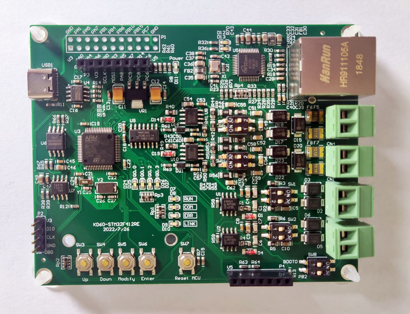
Ethernet
The development board DK60-STM32F412RE has one Ethernet onboard, which is implemented by W5500. The connection between W5500 and MCU is shown in the figure:
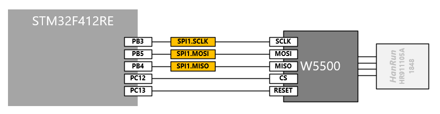
CAN
The development board DK60-STM32F412RE has 2-channel CAN communication onboard, which is realized by TJA1050. as the picture shows:
input Output
4 running indicators (RUN/COM/ERR/LINK)
The development board DK60-STM32F412RE has 4 running indicators onboard, which are directly driven by the MCU pins. as the picture shows:
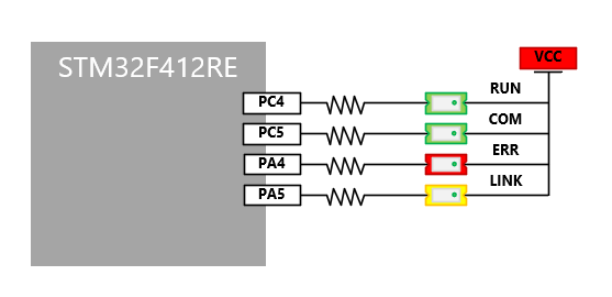
- RUN: Fast blinking means the PLC is running, slow blinking means the PLC is stopped.
- ERR: There is an error in the PLC system.
- COM: A valid communication message is received or sent.
- LINK: Instructions for the Profinet site.
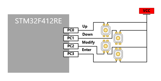
4 input buttons
The development board DK60-STM32F412RE has 4 input buttons onboard. When the button is pressed, the MCU pin is pulled high, as shown in the figure:
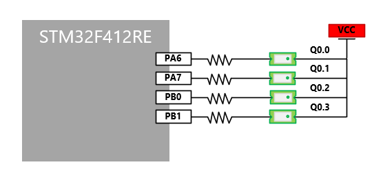
4 output indicators
The development board DK60-STM32F412RE has 4 output indicators onboard, which are directly driven by the MCU pins. as the picture shows:
non-volatile data storage
At present, the KQD platform supports the following ways to save data:
- EEPROM stores AT24 series chips.
- Ferroelectric storage FM25 series chips.
- EEPROM stores AT25 series chips.
The development board DK60-STM32F412RE has two types of memory chips onboard, which are:
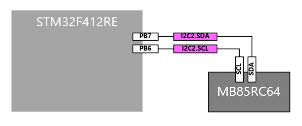
- 1 ferroelectric memory chip MB85RC64 (compatible with AT24).
- 1 FLASH memory chip W25Q128.
Among them, MB85RC64 is connected to the microcontroller through I2C; the connection circuit is shown in the following figure:
Among them, W25Q128 is connected to the microcontroller through SPI; the connection circuit is shown in the following figure:
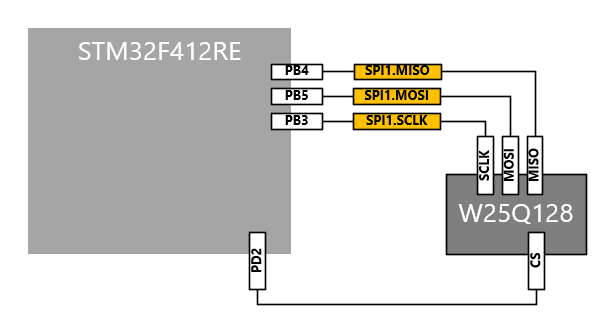
KQD manages all data storage through the NvM module. Because the operation of the CPU will be blocked when the STM32 series MCU modifies the on-chip FLASH data (the CPU running code is also on the on-chip FLASH), so KQD temporarily does not support saving data to the on-chip FLASH, which must be done with the help of an external chip.
The data storage of KQD fully considers the following aspects:
- Due to the interference of communication, the data may be misread due to the interference. Therefore, the read data can be checked twice, that is, read the data twice. If the two read data are consistent, the read data is considered valid. .
- Because there is interference in communication, data may be wrongly written due to the interference when writing data. Therefore, the written data can be optionally confirmed twice, that is, read immediately after writing. If the read data is consistent with the written data, it is considered that Write data is valid.
- Before writing data each time, it is necessary to judge whether the written data is consistent with the existing data. If it is consistent, there is no need to actually perform the erase and write operations, and the write success can be returned directly.
- Regardless of whether it is EEPROM or FLASH, the data must be erased first when writing data. If the controller is powered off before writing new data after erasing, the data will be destroyed. Therefore, on a controller without a power management system, it is recommended to have multiple write backups for data. One of the data backups is damaged and does not affect the validity of the other data backup.
- When there are multiple backups of data, in order to judge the validity of the data backup, the integrity check of the data must be supported.
- Considering the possibility of damage to a single memory chip, backups of the same data can be located on different chips or even different physical media types.
- Data and backups can be retained, that is, when the current data and backups are saved, the last data and backups are not erased, and the oldest data and backups are erased only when the storage medium in the data area is about to be exhausted. The advantage of this is that on the one hand, even if the storage is abnormal, NvM can still restore the most recent data backup, and on the other hand, it reduces the frequency of data erasure and improves the service life of EEPROM or FLASH. Of course, in order to determine whether the data backup is new or old, additional space is needed to save the ID of the data.
display
KQD provides LCD screen driver and menu editing tools. Customers can quickly develop products with LCD human-machine interface based on existing drivers and tools. Its usage is basically the same as the general text screen on the market, but the data is not exchanged through communication, and the LCD screen module directly reads the PLC data in the memory of the single-chip microcomputer for display. The advantage is that the speed is fast and the cost is low. The disadvantage is that it must be made into an all-in-one machine, and the display part and the control part can only be installed together.
Currently supported LCD modules:
- LCD display based on ILI9341
- OLED display based on SSD1306
- LCD display based on ST7565R
- LCD display based on ST7735S
- LCD display based on UC1701X
The above several screens all use the SPI communication mode, because the screen refresh data volume is relatively large and the speed is high, try to open the DMA transmission mode during configuration to reduce the burden of the microcontroller.
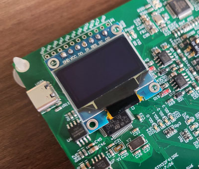
The SSD1306 on the development board DK60-STM32F412RE is located on the upper left of the development board:
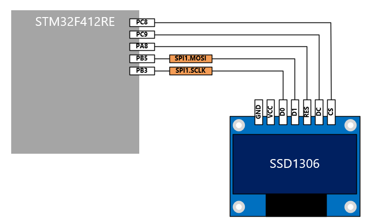
The connection with the microcontroller is shown in the figure:
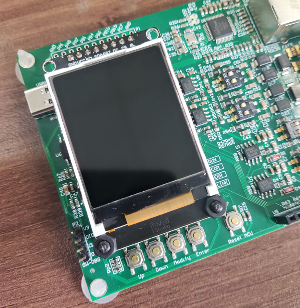
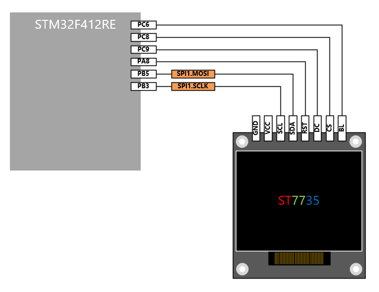
This connector is also compatible with ST7735's IPS color screen:
The connection with the microcontroller is shown in the figure:
4G-CAT1 module
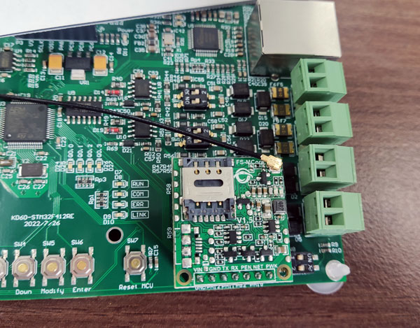
The 4G-CAT1 module FS-MCore-E600NLA onboard the development board DK60-STM32F412RE is located in the lower right of the development board:
The connection with the microcontroller is shown in the figure:
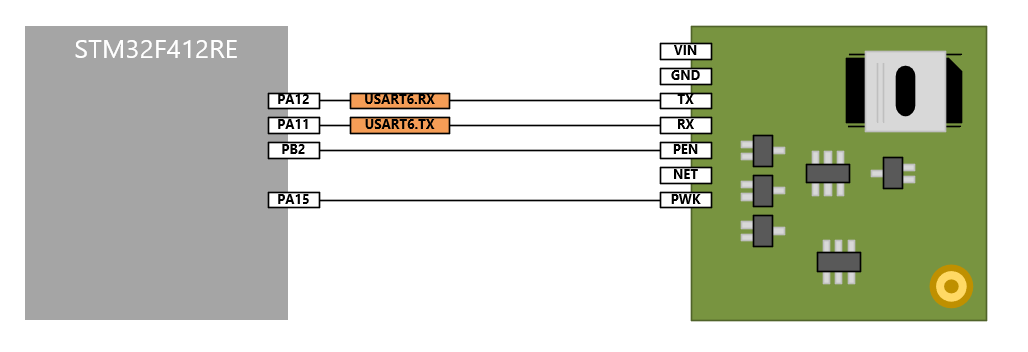
With the help of the 4G-CAT1 module, the development board can be connected to the Kqdnet server to complete the remote monitoring and update of PLC programs, or as a route to remotely monitor and update the programs of third-party PLCs. If the MQTT protocol is configured, with the help of the 4G-CAT1 module, the development board can publish data to the MQTT server and subscribe to the data from the MQTT server.