Wiznet makers

gavinchang

Published May 19, 2023 ©

53 UCC

25 WCC

60 VAR

0 Contests

3 Followers

0 Following

Use ChatGPT to develop W7500S2E-D1 Hardware test Code which Deployed in the W5100S_EVB_PICO

Use ChatGPT to develop W7500S2E-D1 Hardware test Code which Deployed in the W5100S_EVB_PICO
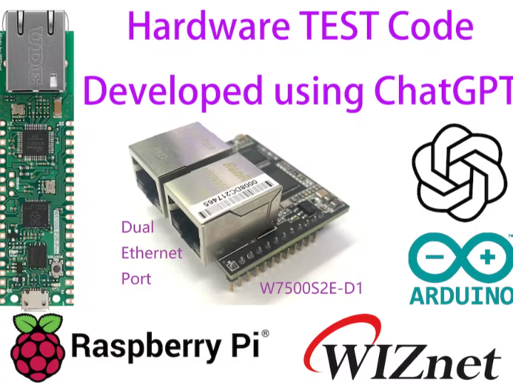
COMPONENTS Hardware components

WIZnet - W5100S-EVB-Pico

x 1

Software Apps and online services

Arduino - Arduino IDE

x 1

Arduino


PROJECT DESCRIPTION
I want to develop a hardware test Code for W7500S2E-D1 use ChatGPT.
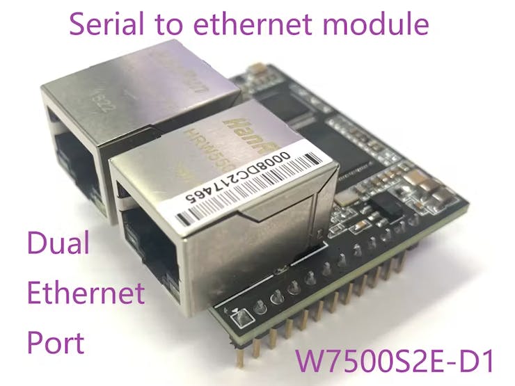
I developed a S2E module with dual network ports, the name is W7500S2E-D1.
W7500S2E-D1 uses WIZNET's W7500 as the MCU, the onboard switch chip can forward serial data to the Ethernet, and has two Ethernet ports(RJ45) onboard, which supports ring network topology, and can be connected between every two modules through a network cable, without the need for Each module is connected to the switch using a network cable, which is convenient for setting up a field network.
Before this product is released, I need to do a detailed test on this module, and I need to design a hardware test program to monitor the operating status of the module. For example, how many modules can be supported on one link at the same time, whether there will be disconnection during operation, and so on.
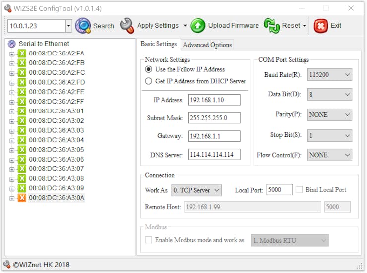
W7500S2E has a setting software running on a PC, named "WIZS2E ConfigTool", which can discover devices by broadcasting, and can view and configure modules. Its interface is as follows:
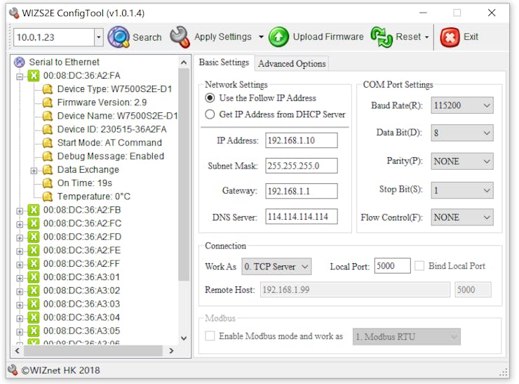
The information for each device is as follows:
But if this program is deployed on a computer, the computer needs to be turned on 24 hours and cannot sleep.
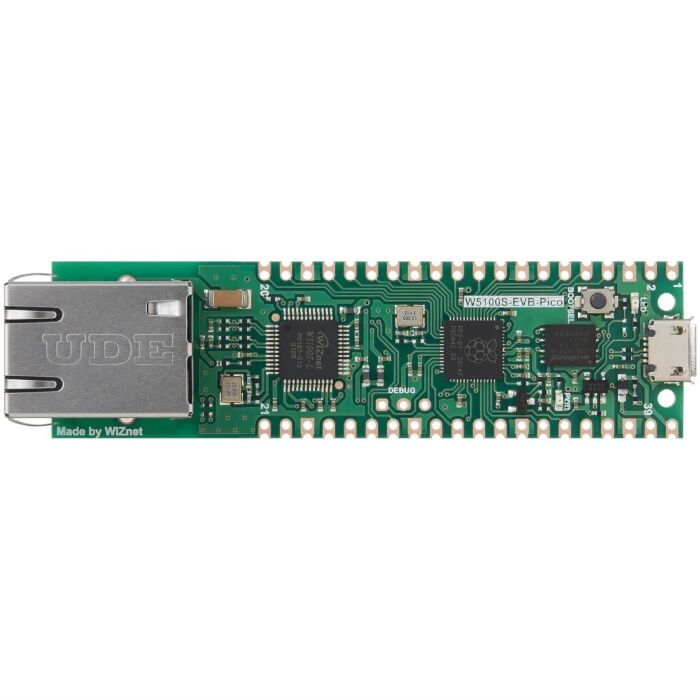
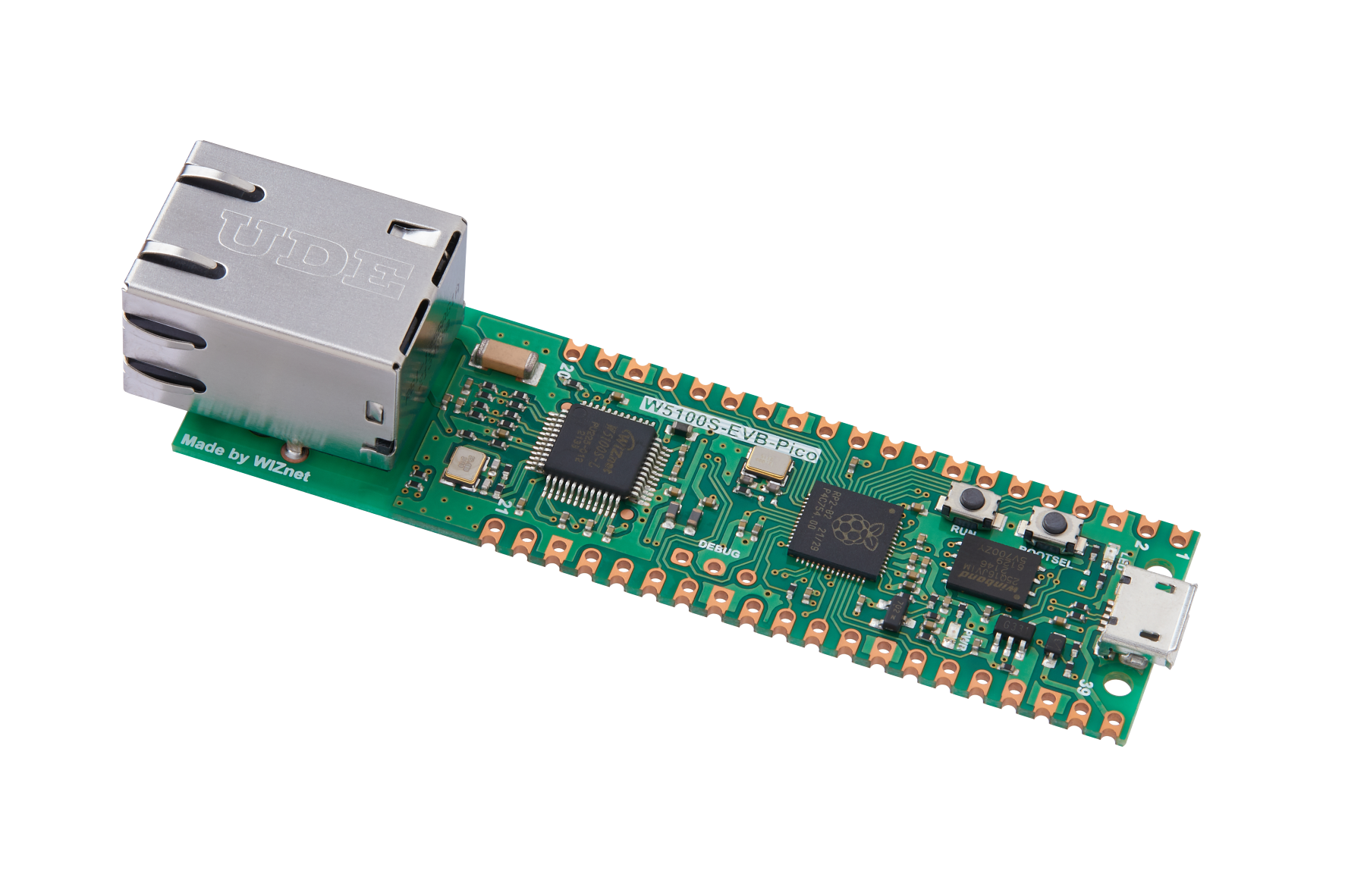
My idea is to deploy the test program on the W5100S_EVB_PICO module. 
WIZnet W5100S-EVB-Pico - RP2040 Board with Ethernet | The Pi Hut | Core  Electronics Australia
This module has an Ethernet chip, which can monitor the running status of the module on the link by interacting with the data of the test network without the participation of the computer. View the status of each device on the web page.
My hardware test code is generated based on the suggestion of ChatGPT. I only made some modifications according to the characteristics of my device. The development process is as follows:
Q1:Under the arduino platform, using rp2040 and W5100S, how to send broadcast data packets
------------------------------------------------------------------------------------------------------------------
ChatGPT:
To send broadcast data packets using Arduino with the RP2040 and W5100S, you can follow these steps:
Set up the Ethernet connection:
Connect the W5100S Ethernet module to the RP2040 board.
Initialize the Ethernet library and set the MAC address, IP address, and subnet mask for the Ethernet module. Here's an example code snippet:
#include <SPI.h>
#include <Ethernet.h>

byte mac[] = { 0xDE, 0xAD, 0xBE, 0xEF, 0xFE, 0xED };
IPAddress ip(192, 168, 0, 100);
IPAddress subnet(255, 255, 255, 0);

EthernetServer server(80);  // Initialize Ethernet server on port 80

void setup() {
  Ethernet.begin(mac, ip, subnet);
  server.begin();
}
Create a UDP broadcast packet:
Declare a UDP object.
Create a IPAddress object for the broadcast address.
Use the beginPacket() function to specify the broadcast address and port number.
Write your data to the packet using the write() function.
End the packet with the endPacket() function. Here's an example code snippet:
#include <EthernetUdp.h>

UDP udp;

void setup() {
  udp.begin(8888);
}

void sendBroadcastPacket() {
  IPAddress broadcastIp(255, 255, 255, 255);  // Broadcast address
  uint16_t port = 1234;                       // Broadcast port

  udp.beginPacket(broadcastIp, port);
  udp.write("Hello, world!");  // Write your data to the packet
  udp.endPacket();
}
Call the sendBroadcastPacket() function whenever you want to send a broadcast packet.
Remember that not all networks support broadcast traffic, so make sure your network infrastructure allows broadcast packets to be transmitted.
---------------------------------------------------------------------------------------------------
Q2:give me a fully testable code
-----------------------------------------------------------------------------------------------------
ChatGPT:
Certainly! Here's a fully testable code example that demonstrates how to send broadcast data packets using Arduino with the RP2040 and W5100S:
#include <SPI.h>
#include <Ethernet.h>
#include <EthernetUdp.h>

byte mac[] = { 0xDE, 0xAD, 0xBE, 0xEF, 0xFE, 0xED };
IPAddress ip(192, 168, 0, 100);
IPAddress subnet(255, 255, 255, 0);
EthernetUDP udp;

void setup() {
  Ethernet.begin(mac, ip, subnet);
  udp.begin(8888);
  Serial.begin(9600);
}

void loop() {
  sendBroadcastPacket();
  delay(1000);
}

void sendBroadcastPacket() {
  IPAddress broadcastIp(255, 255, 255, 255);  // Broadcast address
  uint16_t port = 1234;                       // Broadcast port

  udp.beginPacket(broadcastIp, port);
  udp.write("Hello, world!");  // Write your data to the packet
  udp.endPacket();

  Serial.println("Broadcast packet sent.");
}
In this example, the setup() function initializes the Ethernet connection and starts the UDP communication. The loop() function continuously calls the sendBroadcastPacket() function every second.
The sendBroadcastPacket() function creates a UDP packet with the broadcast IP address and port number. It writes the data "Hello, world!" to the packet and sends it using the endPacket() function. The function also prints a message to the serial monitor indicating that the broadcast packet has been sent.
Upload this code to your Arduino board, open the serial monitor, and you should see the "Broadcast packet sent" message being printed every second. Make sure your Arduino board is connected to a network that allows broadcast traffic, and any device listening on the same network and port should receive the broadcast packet with the message "Hello, world!".
---------------------------------------------------------------------------------------------------
Q3:Can the received packets be printed out?
-----------------------------------------------------------------------------------------------------
ChatGPT:
Yes, you can print out the received packets in the Arduino code. Here's an updated version of the code that includes receiving and printing out the packets:
#include <SPI.h>
#include <Ethernet.h>
#include <EthernetUdp.h>
byte mac[] = { 0xDE, 0xAD, 0xBE, 0xEF, 0xFE, 0xED };
IPAddress ip(192, 168, 0, 100);
IPAddress subnet(255, 255, 255, 0);
EthernetUDP udp;
void setup() {
Ethernet.begin(mac, ip, subnet);
udp.begin(8888);
Serial.begin(9600);
}
void loop() {
sendBroadcastPacket();
receivePackets();
delay(1000);
}
void sendBroadcastPacket() {
IPAddress broadcastIp(255, 255, 255, 255);  // Broadcast address
uint16_t port = 1234;                       // Broadcast port
udp.beginPacket(broadcastIp, port);
udp.write("Hello, world!");  // Write your data to the packet
udp.endPacket();
Serial.println("Broadcast packet sent.");
}
void receivePackets() {
int packetSize = udp.parsePacket();
if (packetSize) {
char packetData[255];
int len = udp.read(packetData, sizeof(packetData) - 1);
if (len > 0) {
packetData[len] = '\0';
Serial.print("Received packet: ");
Serial.println(packetData);
}
}
}
In this updated code, the receivePackets() function is added to handle receiving and printing out the received packets. It checks if there is a UDP packet available using udp.parsePacket(). If a packet is available, it reads the packet data into the packetData array and prints it out on the serial monitor using Serial.println().
After sending the broadcast packet in the sendBroadcastPacket() function, the code calls the receivePackets() function to check if any packets have been received. If there is a received packet, it will be printed out on the serial monitor.
Upload this code to your Arduino board, open the serial monitor, and you should see both the "Broadcast packet sent" message and any received packets being printed out.
---------------------------------------------------------------------------------------------------
Q4: Send a broadcast, then wait for one second, then print out all the data received within one second.
-----------------------------------------------------------------------------------------------------
ChatGPT:
Certainly! Here's an updated version of the code that sends a broadcast packet, waits for one second, and then prints out all the data received within that one-second interval:
#include <SPI.h>
#include <Ethernet.h>
#include <EthernetUdp.h>

byte mac[] = { 0xDE, 0xAD, 0xBE, 0xEF, 0xFE, 0xED };
IPAddress ip(192, 168, 0, 100);
IPAddress subnet(255, 255, 255, 0);
EthernetUDP udp;

void setup() {
  Ethernet.begin(mac, ip, subnet);
  udp.begin(8888);
  Serial.begin(9600);
}

void loop() {
  sendBroadcastPacket();
  delay(1000);
  printReceivedPackets();
}

void sendBroadcastPacket() {
  IPAddress broadcastIp(255, 255, 255, 255);  // Broadcast address
  uint16_t port = 1234;                       // Broadcast port

  udp.beginPacket(broadcastIp, port);
  udp.write("Hello, world!");  // Write your data to the packet
  udp.endPacket();

  Serial.println("Broadcast packet sent.");
}

void printReceivedPackets() {
  unsigned long startTime = millis();
  while (millis() - startTime < 1000) {
    int packetSize = udp.parsePacket();
    if (packetSize) {
      char packetData[255];
      int len = udp.read(packetData, sizeof(packetData) - 1);
      if (len > 0) {
        packetData[len] = '\0';
        Serial.print("Received packet: ");
        Serial.println(packetData);
      }
    }
  }
}
In this updated code, the loop() function calls the printReceivedPackets() function after sending the broadcast packet. The printReceivedPackets() function uses a while loop that runs for one second (1000 milliseconds). It continuously checks for any received packets using udp.parsePacket() and prints out the received packet data if any packets are available.
Upload this code to your Arduino board, open the serial monitor, and you should see the "Broadcast packet sent" message. After one second, it will print out all the received packets within that one-second interval.
---------------------------------------------------------------------------------------------------
Q5: Store the received data in a structure
-----------------------------------------------------------------------------------------------------
ChatGPT:
When data is received, you can store it in a struct. Here is a sample code showing how to store data in a struct as it is received:
#include <SPI.h>
#include <Ethernet.h>
#include <EthernetUdp.h>

byte mac[] = { 0xDE, 0xAD, 0xBE, 0xEF, 0xFE, 0xED };
IPAddress ip(192, 168, 0, 100);
IPAddress subnet(255, 255, 255, 0);
EthernetUDP udp;

struct DataPacket {
  IPAddress senderIP;
  uint16_t senderPort;
  char data[255];
};

DataPacket receivedPacket;

void setup() {
  Ethernet.begin(mac, ip, subnet);
  udp.begin(8888);
  Serial.begin(9600);
}

void loop() {
  sendBroadcastPacket();
  delay(1000);
  printReceivedPackets();
}

void sendBroadcastPacket() {
  IPAddress broadcastIp(255, 255, 255, 255);  // Broadcast address
  uint16_t port = 1234;                       // Broadcast port

  udp.beginPacket(broadcastIp, port);
  udp.write("Hello, world!");  // Write your data to the packet
  udp.endPacket();

  Serial.println("Broadcast packet sent.");
}

void printReceivedPackets() {
  unsigned long startTime = millis();
  while (millis() - startTime < 1000) {
    int packetSize = udp.parsePacket();
    if (packetSize) {
      udp.read((byte*)&receivedPacket, sizeof(receivedPacket));
      Serial.println("Received packet:");
      Serial.print("  Sender IP: ");
      Serial.println(receivedPacket.senderIP);
      Serial.print("  Sender Port: ");
      Serial.println(receivedPacket.senderPort);
      Serial.print("  Data: ");
      Serial.println(receivedPacket.data);
    }
  }
}
In this sample code, we define a structure named DataPacket to store the received data. The DataPacket structure contains the IP address of the sender, the port number of the sender, and the data itself.
In the printReceivedPackets() function, we use the udp.read() function to read the received data into the receivedPacket structure. Then, we print out the IP address of the sender, the port number of the sender, and the data through the Serial.println() function.
Upload this code to your Arduino board, open the serial monitor, you will see the sender's IP address, sender's port number and data printed out. Send broadcast data every second, then store the received data in the structure and print it.
---------------------------------------------------------------------------------------------------
The above is the response of ChatGPT. After I checked the program, I made the following changes
1. Change the CS pin of W5100S to 17 pin of W5100S_EVB_PICO;
2. Modify the broadcast message to "SERH" actually required by W7500S2E-D1;
3. Change the port to the actual port 1460;
4. Modified the default IP and MAC address;
5. Modify the content and naming of the structure, and create an array of 16 to store the information of 16 devices
This is the edited code:
#include <SPI.h>
#include <Ethernet.h>

byte mac[] = { 0x00, 0x08, 0xdc, 0x11, 0x22, 0x33 };  // Your MAC Address
IPAddress localIP(192, 168, 1, 254);                  // Your IP Address
IPAddress broadcastIp(255, 255, 255, 255);            // Broadcast address

EthernetUDP udp;
EthernetServer server(80);

uint8_t count = 0;
unsigned long startTime;

#pragma pack(1) 

struct S2E_DATA {
  char      SERH[4];
  uint8_t   MAC[6];
  uint8_t   DEVICE_ID[16];
  uint8_t   STATE;
  uint8_t   SW_VER[2];
  char      DEVICE_TYPE[16];
  char      DEVICE_NAME[16];
  char      DEVICE_PWD[16];
  uint16_t  HTTP_PORT;
  uint32_t  FW_LEN;
  uint32_t  FW_CHECKSUM;
  uint8_t   DEBUG_FLAG;
  uint8_t   ECHO_FLAG;
  uint8_t   NETBIOS;
  uint8_t   DHCP;
  uint8_t   LOCAL_IP[4];
  uint8_t   SUBNET[4];
  uint8_t   GATEWAY[4];
  uint8_t   DNS[4];
  uint8_t   BAUDRATE;
  uint8_t   DATABIT;
  uint8_t   PARITY;
  uint8_t   STOPBIT;
  uint8_t   FLOWCONTROL;
  uint8_t   MODE;
  uint16_t  LOCAL_PORT;
  uint8_t   REMOTE_IP[4];
  uint16_t  REMOTE_PORT;
  uint8_t   DNS_FLAG;
  char      DOMAIN[32];
  uint16_t  INACTIVITY;
  uint16_t  RECONNECT;
  uint16_t  NAGLE_TIME;
  uint16_t  PACK_LEN;
  uint16_t  KEEP_ALIVE;
  uint8_t   BIND_PORT;
  uint8_t   LINK_CLEAR_BUF;
  uint8_t   LINK_PWD;
  uint8_t   LINK_MSG;
  uint8_t   LINK_CONDITION;
  uint8_t   START_MODE;
  uint16_t  CRC16;
  uint32_t  NET_SEND_NUM;
  uint32_t  NET_RCV_NUM;
  uint32_t  SEC_SEND_NUM;
  uint32_t  SEC_RCV_NUM;
  uint32_t  ON_TIME;
  uint8_t  RUN_MODE;
  uint8_t  TEMPERATURE;  
};

S2E_DATA s2eData;
S2E_DATA s2eDataArray[16];

void setup() {
  Serial.begin(115200);
  while (!Serial) {
    delay(100);
  }
  Ethernet.init(17);  // WIZnet W5100S-EVB-Pico
  Ethernet.begin(mac, localIP);

  // start the server
  server.begin();
  Serial.print("server is at ");
  Serial.println(Ethernet.localIP());

  udp.begin(8888); 
  Serial.println("Broadcast test");
}

void loop() {
  count = 0;
  sendBroadcastPacket();
  printReceivedPackets();
  startTime = millis();
  while (millis() - startTime < 2000) {
  }  
}

void sendBroadcastPacket() {
  char data[] = "SERH";                 // Discovery String
  udp.beginPacket(broadcastIp, 1460);   // open udp socket
  udp.write(data);                      // Write your data to the packet
  udp.endPacket();                      // end 
  Serial.println("Discovery packet sent.");
}

void printReceivedPackets() {
  startTime = millis();
  while (millis() - startTime < 500) {
    int packetSize = udp.parsePacket();
    if (packetSize) {
      int len = udp.read((byte*)&s2eData, sizeof(s2eData) - 1);
      if (len > 0) {
        for(uint8_t m=0; m<16; m++)
        {
          if((s2eDataArray[m].MAC[3] != s2eData.MAC[3])||(s2eDataArray[m].MAC[4] != s2eData.MAC[4])||(s2eDataArray[m].MAC[5] != s2eData.MAC[5]))
          {            
            s2eDataArray[m] = s2eData;
            count ++;   
            Serial.print("Module NO.");
            Serial.print(count);
            Serial.print(" ");
            Serial.print(s2eDataArray[m].DEVICE_TYPE);
            Serial.print(" ");
            Serial.print("MAC:");
            for (int i = 0; i < 6; i++) {
              Serial.printf("%02X",s2eDataArray[m].MAC[i]);
              Serial.print(' ');
            }
            Serial.print("IP:");
            for (int n = 0; n < 4; n++) {
                Serial.print(s2eDataArray[m].LOCAL_IP[n]);
                if(n<3)
                {
                  Serial.print('.');
                }
                else
                {
                  break;
                }
            }
            Serial.println();
            break;
          }
        }
      }
    }
  }
}
And download and run the test use W5100S_EVB_PICO.
During the test, it was found that UDP broadcast packets can be sent and RCV normally, However, the test found that only RCV10 devices reply. After checking the error, it is found that the length of each data packet is 194 bytes, and the default receiving buffer size of W5100S is 2k, so it cannot receive more device information.
I modified the ETHERNET library of Arduino, and modified it in the Ethernet.h file as follows:
1.
//#define ETHERNET_LARGE_BUFFERS
change to:
#define ETHERNET_LARGE_BUFFERS
2.
#define MAX_SOCK_NUM 8
change to:
#define MAX_SOCK_NUM 2
In this way, the RX-BUFFER_SIZE of W5100S can be increased, so that the complete information of 16 devices can be received.
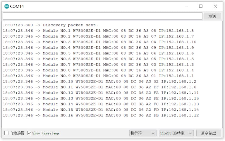
This time, the response messages from the current 16 W7500S2E-D1 modules on the link have been completely received. The message format is as follows:
The message format is as follows:
Module NO.<num> <DEVICE_TYPE> MAC:<MAC address> IP:<IP address>
The basic goal of hardware testing has been achieved, and it is now possible to search and view modules on the link. A further goal is to create an embedded web page where the module's information can be viewed using a browser.
Q6: send < my code> to ChatGPT
-----------------------------------------------------------------------------------------------------ChatGPT:
The code you provided seems to be designed to send a broadcast packet and print the received packets within 500 milliseconds. It uses a structure S2E_DATA to store the received packet data.
Here's a breakdown of the code's functionality:
The setup() function initializes the serial communication, Ethernet module, server, and UDP socket. It also prints the server's IP address.
The loop() function repeatedly sends a broadcast packet, waits for 500 milliseconds, and then calls the printReceivedPackets() function.
The sendBroadcastPacket() function sends a UDP packet containing the "SERH" discovery string to the broadcast IP address.
The printReceivedPackets() function reads the received packets and stores them in the s2eDataArray array. It checks if the MAC address of the received packet already exists in the array to avoid duplicate entries. If it's a new MAC address, the received packet data is stored in the array and printed.
It's important to note that the s2eData structure has a fixed size of 192 bytes (sizeof(s2eData)). If the received packet size is larger than this, it may result in truncated data. Make sure the size of the received packet matches the structure size to ensure correct data parsing.
Please review the code, ensure it meets your requirements, and modify it as needed.
Q7: I want to build a webserver so that I can view the information of the s2eDataArray structure on the browser
-----------------------------------------------------------------------------------------------------
ChatGPT:
To build a web server that allows you to view the information from the s2eDataArray structure in a browser, you can modify your code as follows:
#include <SPI.h>
#include <Ethernet.h>

byte mac[] = { 0x00, 0x08, 0xdc, 0x11, 0x22, 0x33 };  // Your MAC Address
IPAddress localIP(192, 168, 1, 254);                  // Your IP Address

EthernetServer server(80);

struct S2E_DATA {
  // Your structure members here
};

S2E_DATA s2eDataArray[16];

void setup() {
  Serial.begin(115200);
  while (!Serial) {
    delay(100);
  }
  Ethernet.init(17);  // WIZnet W5100S-EVB-Pico
  Ethernet.begin(mac, localIP);

  server.begin();
  Serial.print("Server is running at ");
  Serial.println(Ethernet.localIP());
}

void loop() {
  EthernetClient client = server.available();
  if (client) {
    processRequest(client);
    client.stop();
  }
}

void processRequest(EthernetClient client) {
  String request = client.readStringUntil('\r');
  client.readStringUntil('\n');

  if (request.indexOf("GET /") != -1) {
    sendResponse(client);
  }
}

void sendResponse(EthernetClient client) {
  client.println("HTTP/1.1 200 OK");
  client.println("Content-Type: text/html");
  client.println("Connection: close");
  client.println();

  client.println("<!DOCTYPE html>");
  client.println("<html>");
  client.println("<head>");
  client.println("<title>S2E Data</title>");
  client.println("</head>");
  client.println("<body>");
  client.println("<h1>S2E Data</h1>");

  for (int i = 0; i < 16; i++) {
    client.print("<h2>Module NO.");
    client.print(i + 1);
    client.print("</h2>");
    client.print("<p>DEVICE TYPE: ");
    client.print(s2eDataArray[i].DEVICE_TYPE);
    client.print("</p>");
    client.print("<p>MAC: ");
    for (int j = 0; j < 6; j++) {
      client.print(String(s2eDataArray[i].MAC[j], HEX));
      if (j < 5) {
        client.print(":");
      }
    }
    client.print("</p>");
    client.print("<p>IP: ");
    client.print(s2eDataArray[i].LOCAL_IP[0]);
    client.print(".");
    client.print(s2eDataArray[i].LOCAL_IP[1]);
    client.print(".");
    client.print(s2eDataArray[i].LOCAL_IP[2]);
    client.print(".");
    client.print(s2eDataArray[i].LOCAL_IP[3]);
    client.print("</p>");
    client.println("<hr>");
  }

  client.println("</body>");
  client.println("</html>");
}
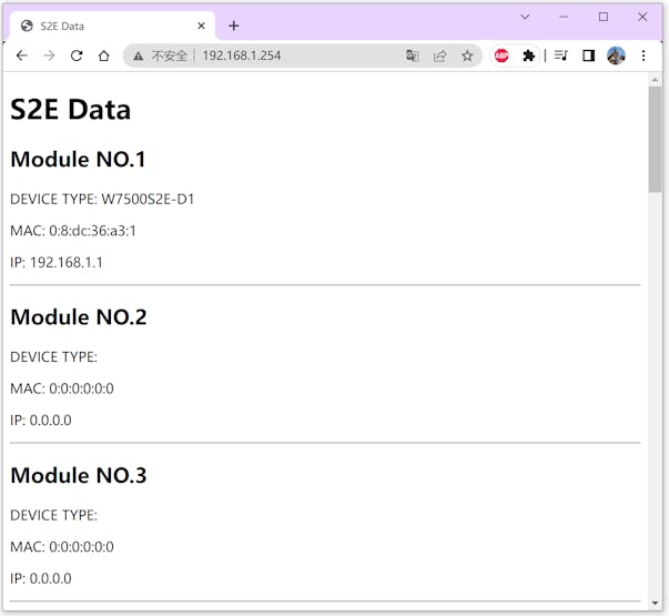
In this modified code, a web server is created using the Ethernet library. The loop() function continuously checks for client connections. When a client connects, the processRequest() function is called to handle the request. The server responds to the client with HTML content displaying the information from the s2eDataArray structure.
The sendResponse() function constructs the HTML response to display the data. It iterates over each element in the s2eDataArray and prints the module number, device type, MAC address, and IP address. The response is sent back to the client.
To access the data in a browser, you can open the IP address of the Arduino Ethernet shield in the browser, for example: http://192.168.1.254. The browser will display the S2E data with the module numbers, device types, MAC addresses, and IP addresses.
Please note that this code assumes the presence of an Ethernet shield or module connected to your Arduino board. Make sure to adjust the MAC address and IP address variables (mac and localIP) according to your network configuration.
---------------------------------------------------------------------------------------------------
After running the test, enter the address in the browser: http://192.168.1.254, you can see the following device information.
In order to display interface optimization and beautification, continue to communicate with ChatGPT.
Q8: Put each array of html on the same line, and choose a different color for each type, change the title to WIZS2E ConfigTool Webpage, and the webpage can be refreshed automatically.
-----------------------------------------------------------------------------------------------------
ChatGPT:
To change the title to "WIZS2E ConfigTool Webpage", you need to modify"sendResponse"the HTML part in the function.
Display different color for each typeyou need to use appropriate CSS styles in your HTML code.
To add auto-refresh functionality in HTML files, you can use attributes and attributes <meta> in HTML tags. Here is a modified code example:
"http-equiv" "content ".
void sendResponse(EthernetClient client) {
  client.println("HTTP/1.1 200 OK");
  client.println("Content-Type: text/html");
  client.println("Connection: close");
  client.println();

  client.println("<!DOCTYPE html>");
  client.println("<html>");
  client.println("<head>");
  client.println("<title>WIZS2E ConfigTool Webpage</title>");
  client.println("<meta http-equiv=\"refresh\" content=\"5\">");  
  client.println("<style>");
  client.println(".device-type { color: green; font-size: 14px; }");
  client.println("</style>");
  client.println("</head>");
  client.println("<body>");
  client.println("<h1>WIZS2E ConfigTool Webpage</h1>");

  for (int i = 0; i < 16; i++) {
    if (s2eDataArray[i].DEVICE_TYPE[0] == '\0') {
      continue;  //skip invalid data
    }    
    client.print("<h2>Module NO.");
    client.print(i + 1);
    client.print("</h2>");
    client.print("<p><span class=\"device-type\">DEVICE TYPE: ");
    client.print(s2eDataArray[i].DEVICE_TYPE);
    client.print("</span></p>");
    client.print("<p>MAC: ");
    for (int j = 0; j < 6; j++) {
      client.print(String(s2eDataArray[i].MAC[j], HEX));
      if (j < 5) {
        client.print(":");
      }
    }
    client.print("</p>");
    client.print("<p>IP: ");
    client.print(s2eDataArray[i].LOCAL_IP[0]);
    client.print(".");
    client.print(s2eDataArray[i].LOCAL_IP[1]);
    client.print(".");
    client.print(s2eDataArray[i].LOCAL_IP[2]);
    client.print(".");
    client.print(s2eDataArray[i].LOCAL_IP[3]);
    client.print("</p>");
    client.println("<hr>");
  }

  client.println("</body>");
  client.println("</html>");
}
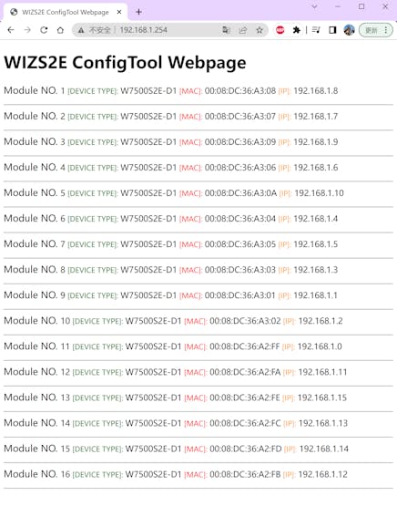
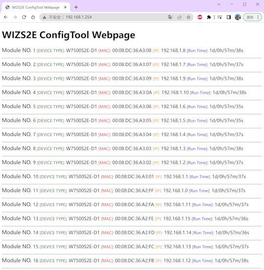
In the above modified code, I added <meta> a label and "http-equiv" set the use attribute to "refresh", and "content" the attribute was set to "5", which means that the page is automatically refreshed every 5 seconds. You can adjust the refresh interval according to your needs.
---------------------------------------------------------------------------------------------------
The display interface of the embedded web page changes to the following state:
Finally, The[ Run Time] display is added to the web page. as follows:
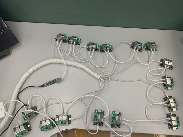
This has basically met my test requirements, the following is a test site photo, the network cable connects the adjacent W7500S2E-D1modules(Total 16pcs);
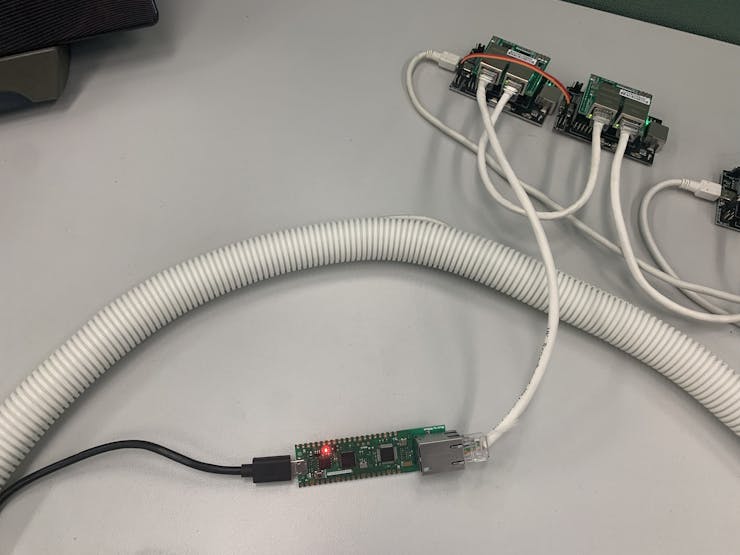
The hardware monitoring code is deployed on W5100S_EVB_PICO:
Done.
Documents
  • Hardware test Code for W7500S2E-D1

    Hardware test Code for W7500S2E-D1

  • Hardware test Code for W7500S2E-D1

    Github

Comments Write