
RP2040-ETH-DVI-ZERO: Adafruit IO Dashboard Monitor ( HDMI / DVI Mode )
A newly developed Raspberry Pi RP2040 development board with DVI interface and Ethernet. This project can display adafruit IO dashboard and followup any change.


Raspberry Pi - RP2040
x 1
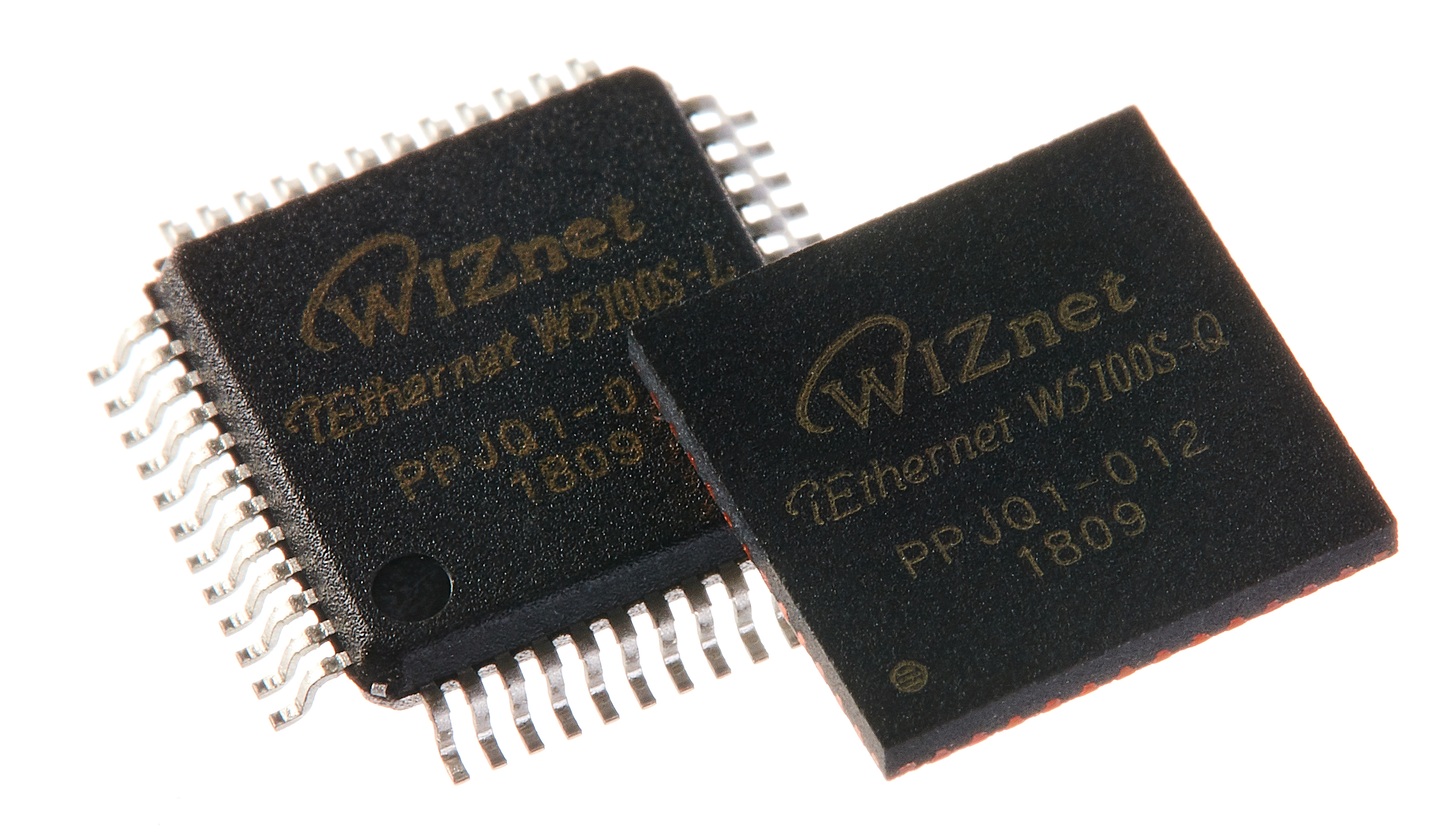
WIZnet - W5100S
x 1

Arduino - Arduino IDE
x 1
adafruit - Adafruit IO
x 1
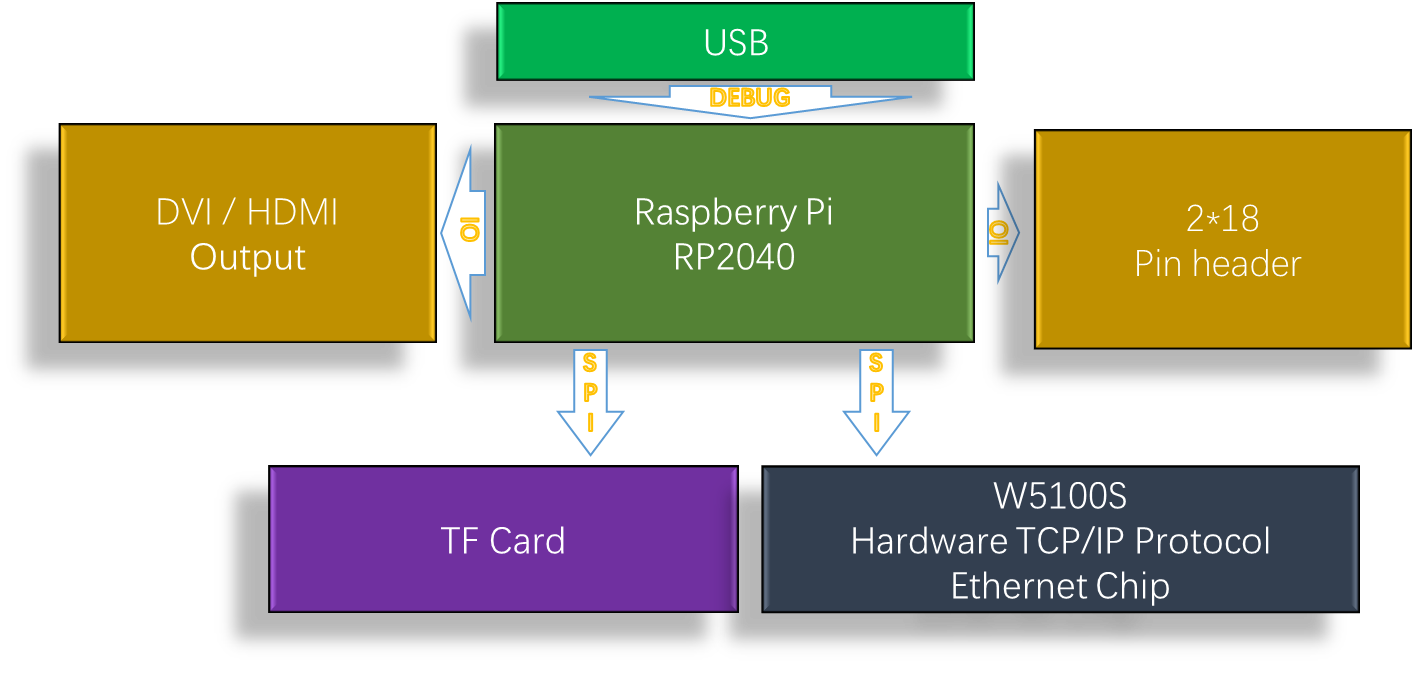
I have newly developed a Raspberry Pi RP2040 development board, which has a DVI/HDMI output interface, uses W5100S as network access, and has a TF card socket. I named this development board "RP2040-ETH-DVI-ZERO" .
As far as I know, RP2040-ETH-DVI-ZERO is the first RP2040 DVI development board which have network function.

RP2040-ETH-DVI-ZERO adopts the same external dimensions and interface design as the official Raspberry Pi ZERO W, and RP2040-ETH-DVI-ZERO can use the Raspberry Pi ZERO W official case.

RP2040-ETH-DVI-ZERO can perform network communication and image DVI output display at the same time.
It can generate a 320*240 resolution image and output it to the monitor by expanding to 640*480(60Hz)

Why should I develop RP2040-ETH-DVI-ZERO?
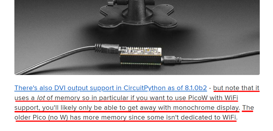
There are many RP2040 development boards with DVI interfaces on the market, but none of them have network communication functions. Because the wireless communication part of PICO W occupies a large amount of dynamic memory, the DVI output function cannot be used at the same time as the network function, or its use is greatly restricted. Because using W5100S allows network communication using only a small amount of dynamic memory, so I developed RP2040-ETH-DVI-ZERO and project.
This is just 2% of the dynamic memory used by W5100S。

This is 25% of the dynamic memory used by PICO W, and the comparison is quite obvious.

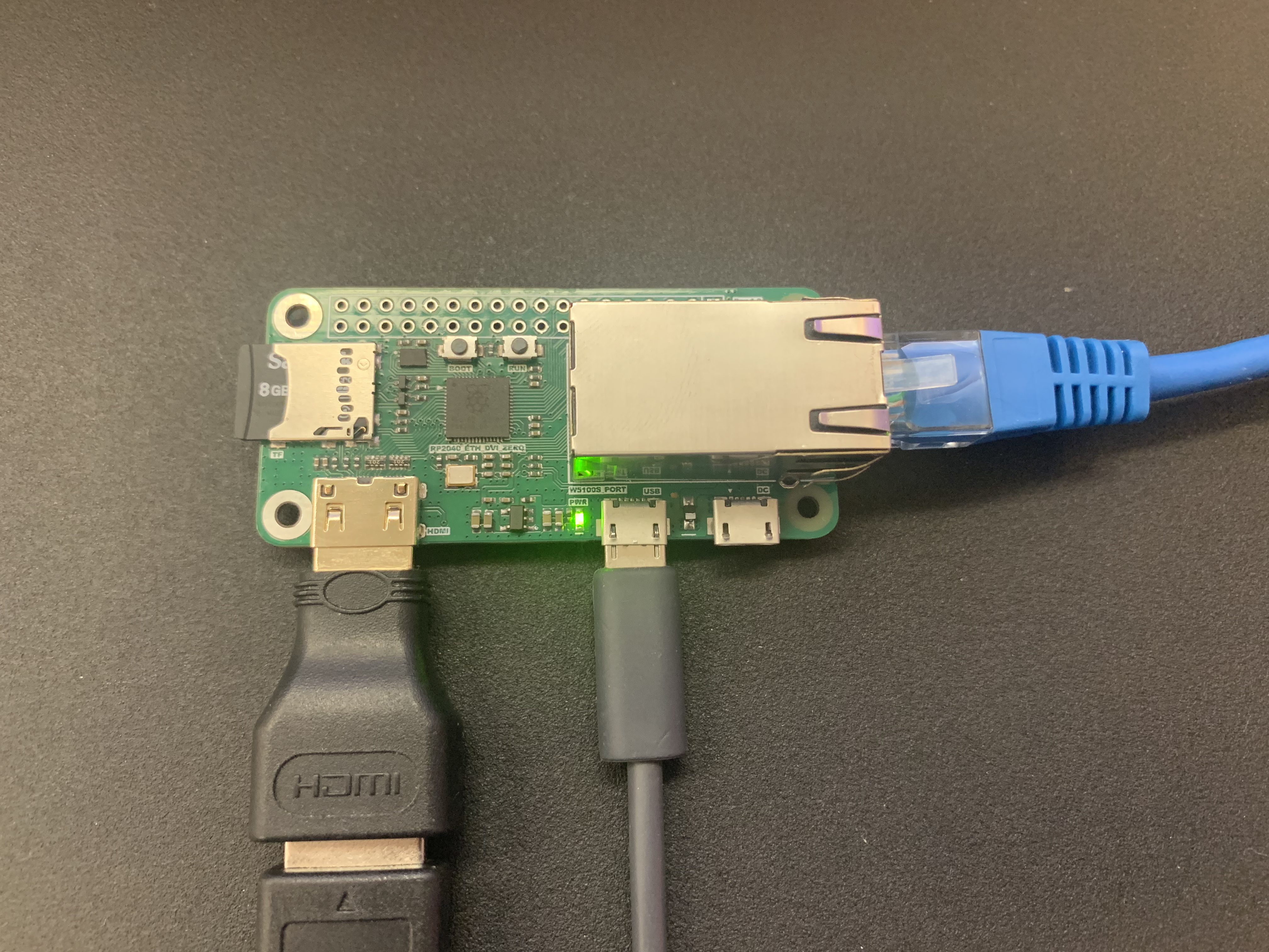
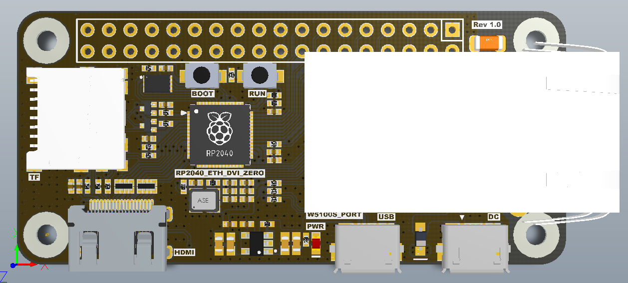
RP2040-DVI-ETH-ZERO Hardware:
Top view:
Bottom view:
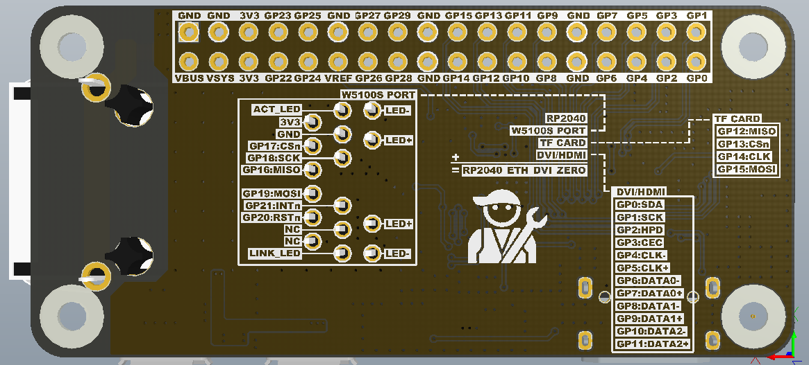
I use the same pin design as W5100S_EVB_PICO for the W5100S part, so I can use all the reference codes of W5100S_EVB_PICO.
The name of this project is “Adafruit IO Dashboard Monitor”. My idea is to develop a universal dashboard display interface for adafruit.io. All display content is obtained from adafruit.io, including displaying the dashboard framework of adafruit.io and parsing all Blocks contained in the dashboard, automatically subscribing to all "feed" content contained in the dashboard, and outputting it to the monitor through DVI.
Because it is a universal display frame, I did not define any fixed parameters in the program. All parameters are obtained through Adafruit.io, including the display frame.
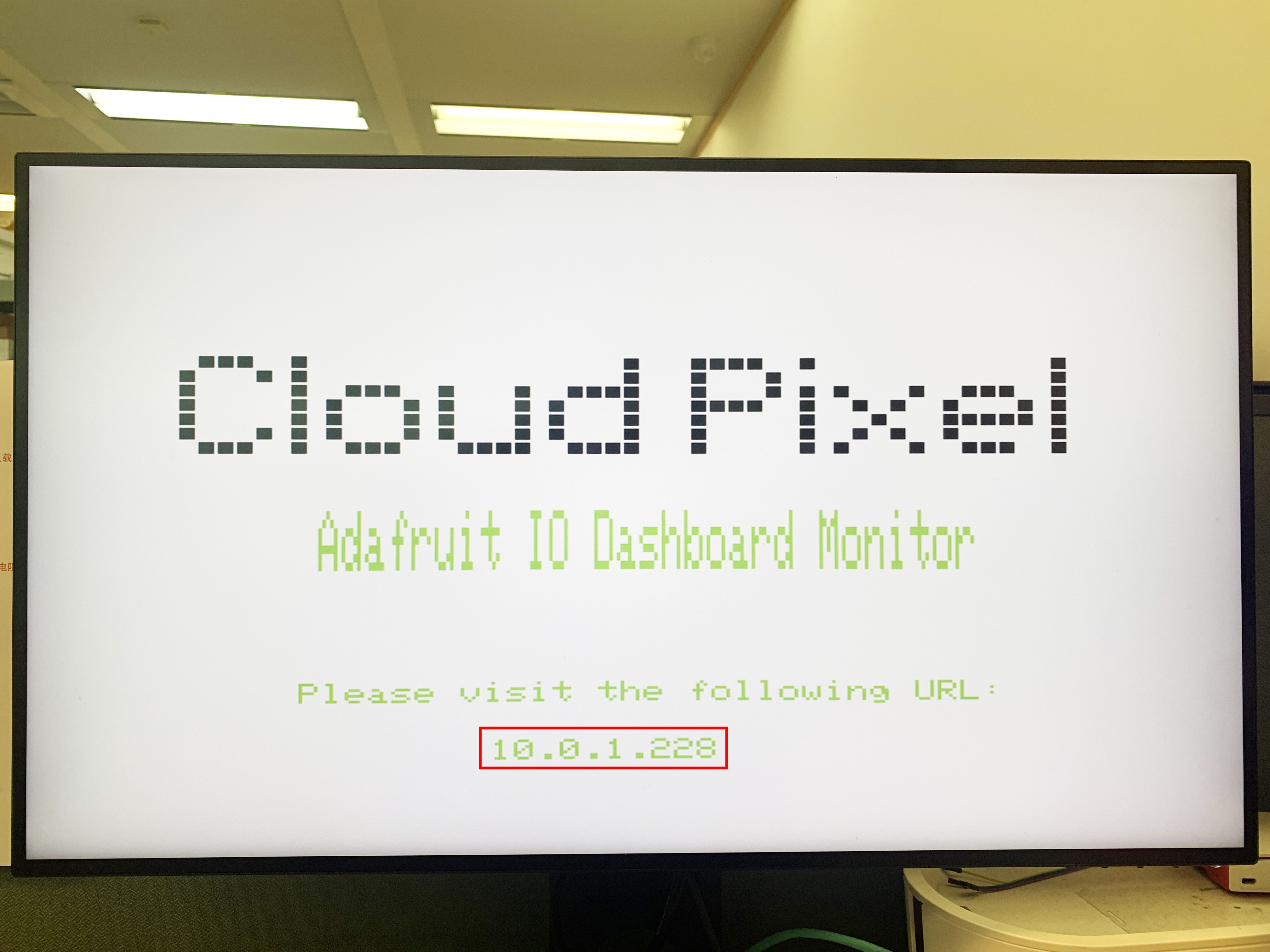
Because there are no fixed parameters, we need to enter adafruit access parameters through the embedded web page when powering on for the first time.
RP2040-ETH-DVI-ZERO's screen display:
Enter three parameters by browsing the embedded web page, namely adafruit's name, key, and dashboard id.
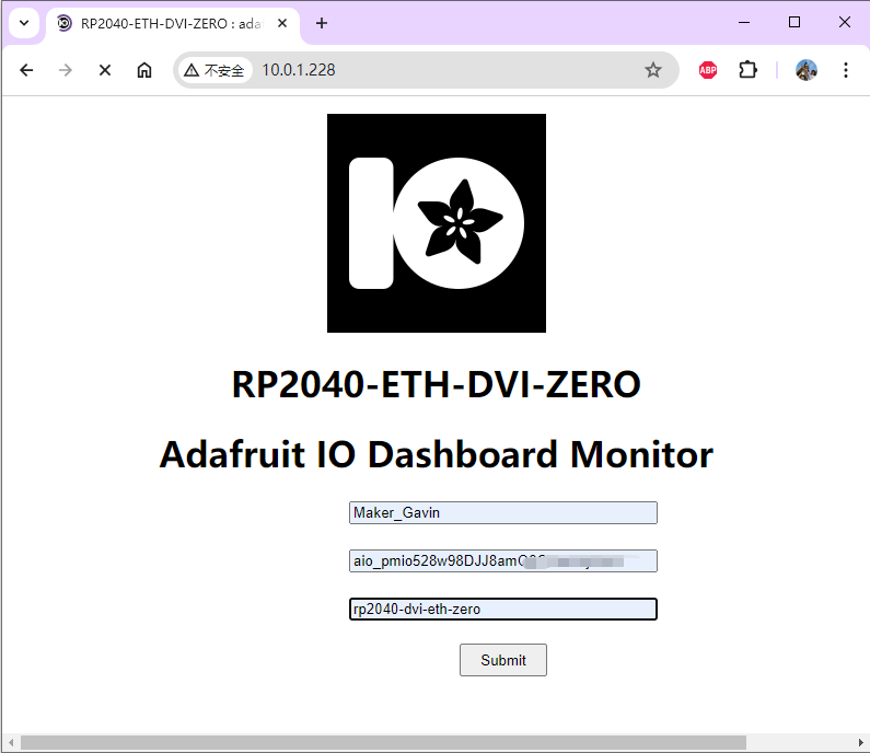
Enter three parameters by browsing the embedded web page, namely adafruit's name, key, and dashboard id. After clicking "Submit", it will be stored in the flash inside RP2040. Next time you turn on the RP2040-ETH-DVI-ZERO, that will skip the step of obtaining parameters from the browser and directly run "get the adafruit dashboard".
HTML code of this embedded webpage:
#ifndef PROGMEM
#define PROGMEM
#endif

const char html_page[] PROGMEM = {
    "HTTP/1.1 200 OK\r\n"
    "Content-Type: text/html\r\n"
    "Connection: close\r\n"  // the connection will be closed after completion of the response
    //"Refresh: 5\r\n"         // refresh the page automatically every n sec
    "\r\n"
    "<!DOCTYPE HTML>"
    "<html>"
    "<head>"
      "<meta charset='UTF-8'>"
      "<title>RP2040-DVI-ETH-ZERO : adafruit io monitor</title>"
      "<link rel='icon' href='https://cdn-learn.adafruit.com/guides/images/000/000/570/medium800/AIO_LOGO.png' type='image/x-icon'>"
    "</head>"
    "<body>"
    "<p style='text-align:center;'>"
    "<img alt='ChatGPT' src='https://cdn-learn.adafruit.com/guides/images/000/000/570/medium800/AIO_LOGO.png' height='200' width='200'>"
    "<h1 align='center'>RP2040-DVI-ETH-ZERO</h1>"
    "<h1 align='center'>adafruit io monitor</h1>"
    "<div style='width:900px;margin: 0 auto;text-align: center'>"
    "<form action='/' method='post'>"
    "<input type='text' placeholder='adafruit io user' size='35' name='adafruit_user' required='required'/><br><br>"
    "<input type='text' placeholder='adafruit io key' size='35' name='adafruit_key' required='required'/><br><br>"
    "<input type='text' placeholder='adafruit io dashboard key' size='35' name='dashboard_key' required='required'/><br><br>"
    "<input type='submit' value='Submit' style='height:30px; width:80px;'/>"
    "</form>"
    "<div style='text-align: left;'>"
    "<h5>"
    "</h5>\r\n"
    "</div>"
    "</div>"
    "</body>\r\n"
    "<html>\r\n"
};
Obtaining the dashboard of adafruit.io, we can get all the layout the frame which needed to display in the screen, including all block information, positions, size, corresponding Feeds and Groups.
#define dashboard_layout_max 16
struct _Dashboard_Layout{
boolean exist = false;
uint8_t x;
uint8_t y;
uint8_t x_size;
uint8_t y_size;
String id;
};
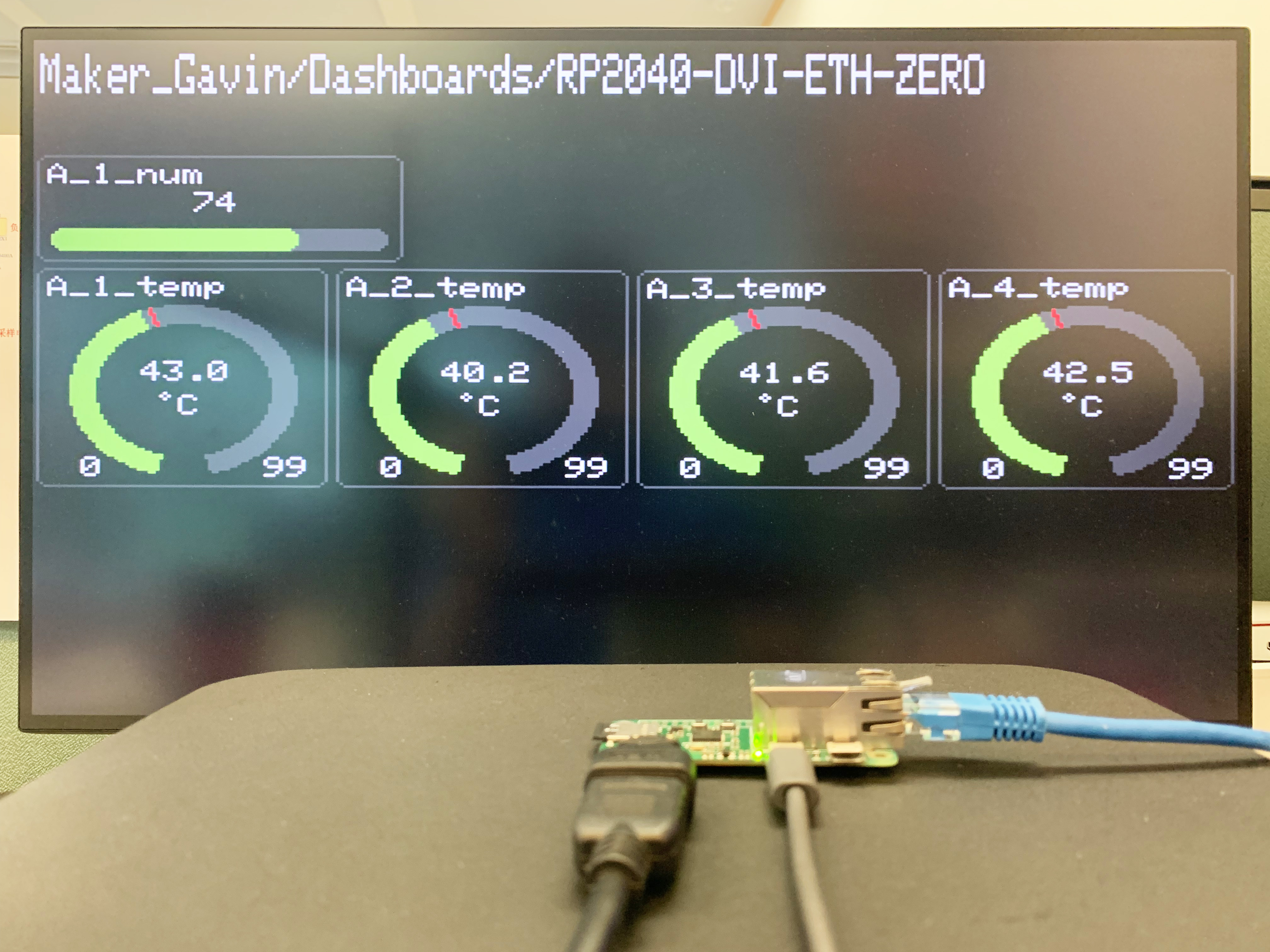
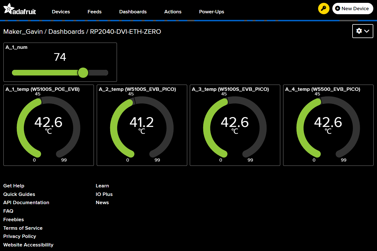
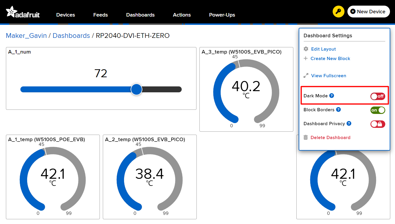
_Dashboard_Layout dashboard_layout[dashboard_layout_max];This is the Adafruit io web version of the dashboard "RP2040-DVI-ETH-ZERO".
A_1_temp (W5100S_POE_EVB_PICO)
A_2_temp (W5100S_EVB_PICO)
A_3_temp (W5100S_EVB_PICO)
A_4_temp (W5500_EVB_PICO)
Four PICO boards upload these built-in temperature sensor data to adafruit.io every 10 seconds.
(Because I am using Adafruit’s free service, there is a limit on the number of communications)
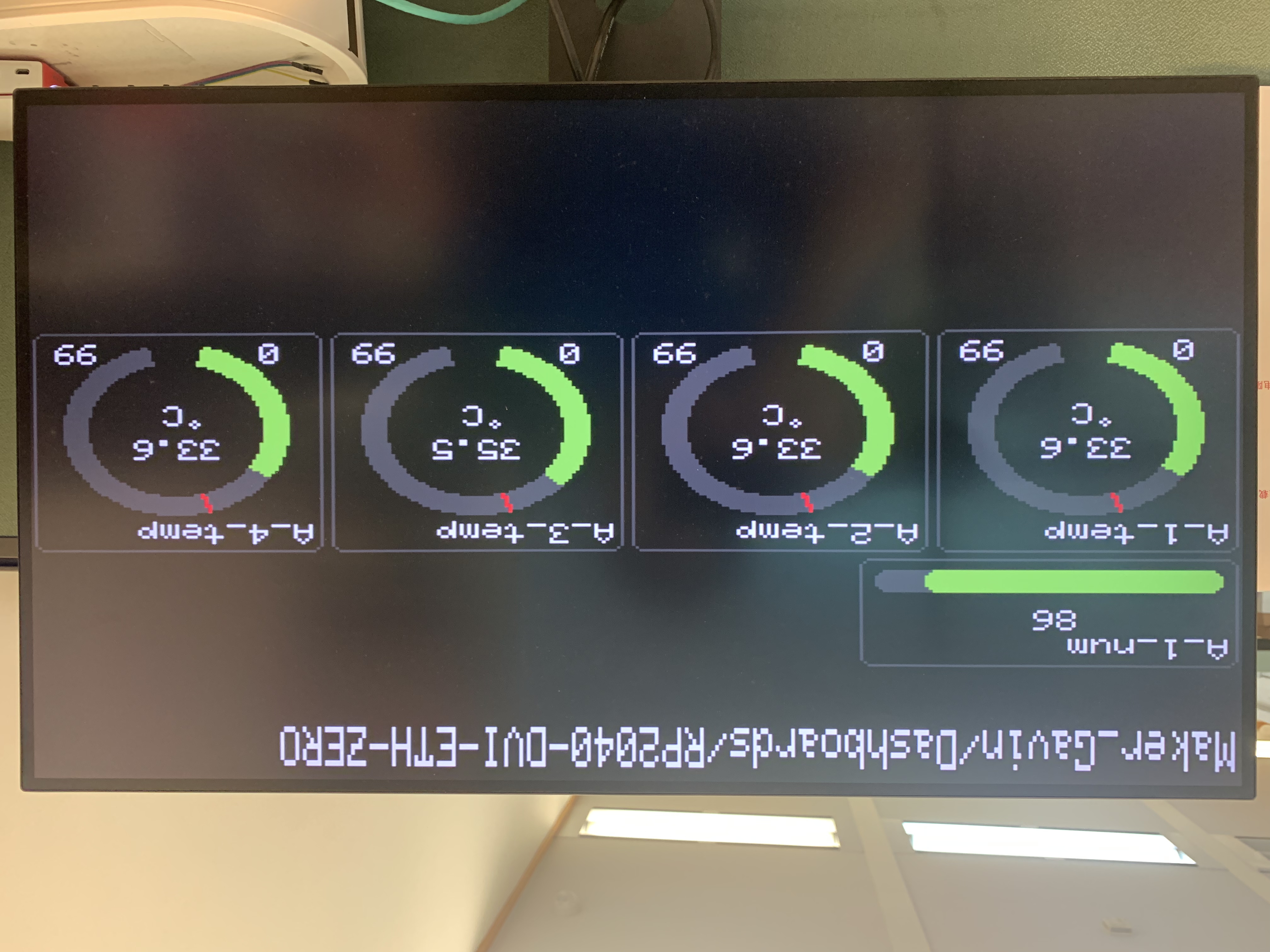
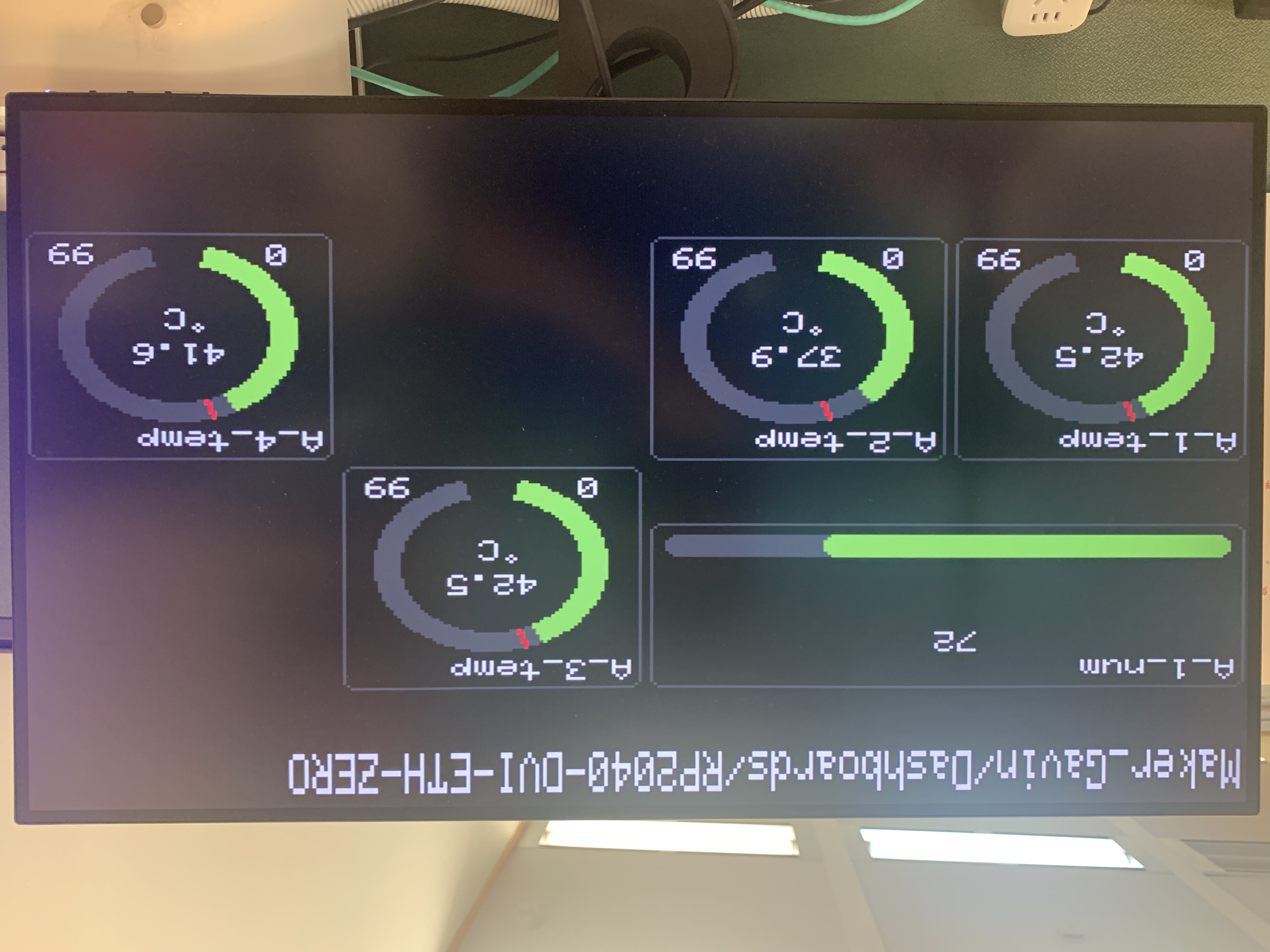
This is the dashboard after I obtained the dashboard information and reconstructed the display frame.

While parsing the dashboard message, we also obtained all relevant Feed and Group information. The code will automatically subscribe to all Feeds and Groups and put them into the message callback processing function.
#define dashboard_block_max 16
struct _Dashboard_block{
  boolean exist = false;
  String id;
  String name;
  String type;
  String label;
  uint16_t minValue;
  uint16_t maxValue;
  uint16_t minWarning;
  uint16_t maxWarning;
  uint8_t decimal;
  String feed_id;
  String feed_key;
  String feed_name;
  String group_key;
};
_Dashboard_block dashboard_block[dashboard_block_max];
message callback processing code:
// you can also attach multiple feeds to the same
// meesage handler function. both counter and counter-two
// are attached to this callback function, and messages
// for both will be received by this function.
void feed_handle(AdafruitIO_Data *data) {
  Serial.print("received <- ");
  // since we are using the same function to handle
  // messages for two feeds, we can use feedName() in
  // order to find out which feed the message came from.
  Serial.print(data->feedName());
  Serial.print(" ");
  // print out the received count or counter-two value
  Serial.println(data->value());

  for(int i=0; i<dashboard_block_max; i++)
  {
    String Feed_data_decimal;
    if(dashboard_block[i].feed_key == data->feedName())
    {
      display.setTextColor(DashBoard_Text_Color);

      std::string Feed_data_decimal(data->value());
      if(Feed_data_decimal.find('.')!= -1)
      {
        Feed_data_decimal = (Feed_data_decimal.substr(0,Feed_data_decimal.find('.')+1+dashboard_block[i].decimal));
        Serial.println(Feed_data_decimal.c_str());
      }
      if(dashboard_block[i].type == "slider")
      {
        display.fillRoundRect(dashboard_layout[i].x*20+4,dashboard_layout[i].y*20+2+_y+dashboard_layout[i].y_size*20-16,dashboard_layout[i].x_size*20-8,10,3,DashBoard_Back_Color);
        display.fillRoundRect(dashboard_layout[i].x*20+5,dashboard_layout[i].y*20+2+_y+dashboard_layout[i].y_size*20-15,dashboard_layout[i].x_size*20-10,8,3,adafruit_grey);
        uint16_t slider_point = (atoi(data->value()))*(dashboard_layout[i].x_size*20-10)/100;

        display.fillRoundRect(dashboard_layout[i].x*20+5,dashboard_layout[i].y*20+2+_y+dashboard_layout[i].y_size*20-15,slider_point,8,3,DashBoard_Bar_Color);
        display.fillRect(dashboard_layout[i].x*20+dashboard_layout[i].x_size*10-7,dashboard_layout[i].y*20+4+_y+10,30,10,DashBoard_Back_Color);
        display.setTextSize(1);
        display.setCursor(dashboard_layout[i].x*20+dashboard_layout[i].x_size*10-7,dashboard_layout[i].y*20+4+_y+10);
        display.println(atoi(data->value()));

      }
      else if(dashboard_block[i].type == "gauge")
      {
display.fillArc(dashboard_layout[i].x*20+dashboard_layout[i].x_size*10,dashboard_layout[i].y*20+4+_y+40, 24, 30, 105, 75, DashBoard_Bar_Back_Color);
        display.setCursor(dashboard_layout[i].x*20 + 13, dashboard_layout[i].y*20 + _y + dashboard_layout[i].y_size*20 - 12);
        display.println(dashboard_block[i].minValue);
        display.setCursor(dashboard_layout[i].x*20 + dashboard_layout[i].x_size*20 -18 , dashboard_layout[i].y*20 + _y + dashboard_layout[i].y_size*20 - 12);
        display.println(dashboard_block[i].maxValue);
        display.setCursor(dashboard_layout[i].x*20+dashboard_layout[i].x_size*10, dashboard_layout[i].y*20+4+_y+48);

        if((atoi(data->value()) <= dashboard_block[i].minWarning)||(atoi(data->value()) >= dashboard_block[i].maxWarning))
        {
display.fillArc(dashboard_layout[i].x*20+dashboard_layout[i].x_size*10,dashboard_layout[i].y*20+4+_y+40, 24, 30, 105, 105+ (atoi(data->value()) * 330 / 100), adafruit_red);
          DashBoard_warning = dashboard_block[i].maxWarning * 330 / 100;
display.fillArc(dashboard_layout[i].x*20+dashboard_layout[i].x_size*10,dashboard_layout[i].y*20+4+_y+40, 24, 30, 105+DashBoard_warning-1, 105+DashBoard_warning, BLACK);
        }
        else
        {
display.fillArc(dashboard_layout[i].x*20+dashboard_layout[i].x_size*10,dashboard_layout[i].y*20+4+_y+40, 24, 30, 105, 105+ (atoi(data->value()) * 330 / 100), DashBoard_Bar_Color);
          DashBoard_warning = dashboard_block[i].maxWarning * 330 / 100;          display.fillArc(dashboard_layout[i].x*20+dashboard_layout[i].x_size*10,dashboard_layout[i].y*20+4+_y+40, 24, 30, 105+DashBoard_warning-1, 105+DashBoard_warning, adafruit_red);
        }
        display.fillRect(dashboard_layout[i].x*20+dashboard_layout[i].x_size*10-11,dashboard_layout[i].y*20+4+_y+30,30,10,DashBoard_Back_Color);

        display.setTextSize(1);
        display.setCursor(dashboard_layout[i].x*20+dashboard_layout[i].x_size*10-11,dashboard_layout[i].y*20+4+_y+30);
        display.println(Feed_data_decimal.c_str());
      }
    }
  }
}
After updating the Feed and Group message data to the diaplay, the effect is as follows:
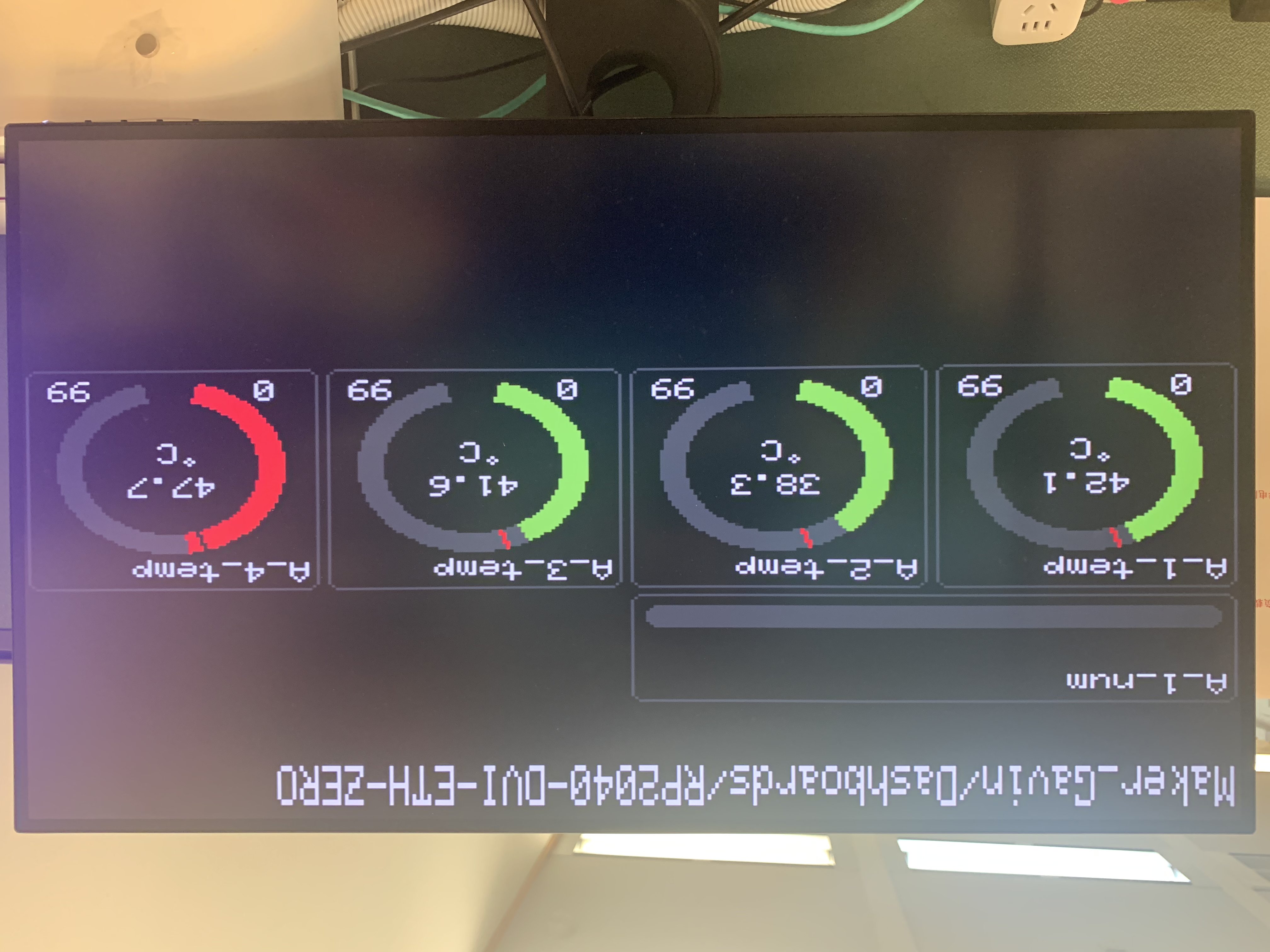
Because this project does not use fixed display parameters, it can change followup with any changes in the page layout of the dashboard web version.
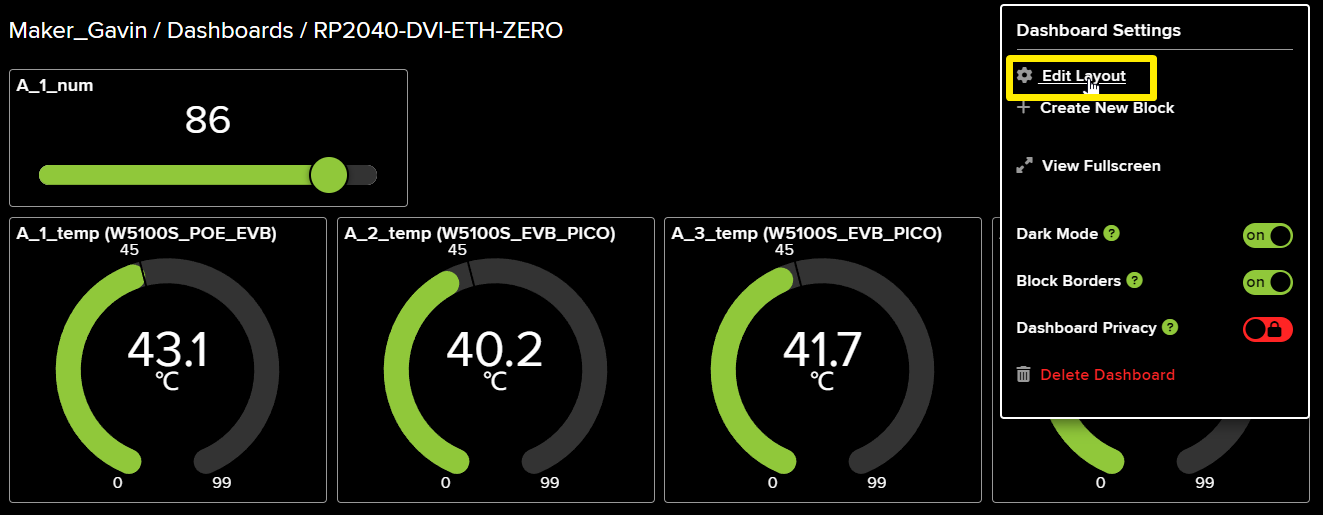
After Edit Layout and save it.

Then the display interface of RP2040-ETH-DVI-ZERO will also change the display layout accordingly.
Dashboards contain warning value information for each block, and the display interface will also display differently based on the warning value.
I artificially increased the temperature of A_4_temp (W5500_EVB_PICO), and you can see a warning message on the screen display .
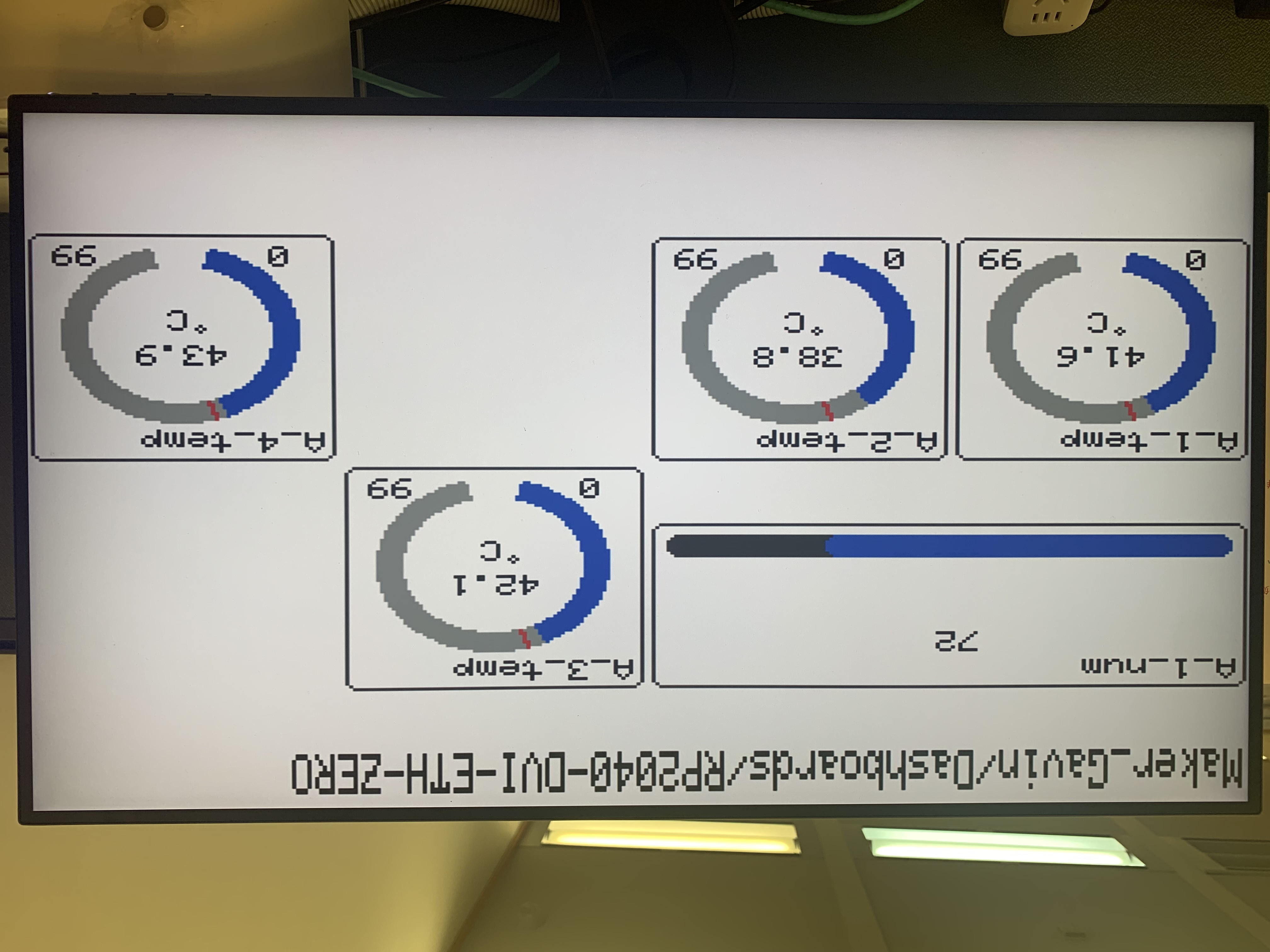
Moreover, the dark mode and light mode of the display interface are also automatically switched.
light mode view:
I developed it using Arduino, and these are all the libraries used in this project:
#include <AdafruitIO_Ethernet.h>
#include <SPI.h>
#include <EEPROM.h>
#include <Ethernet.h>
#include <LittleFS.h>
#include <SD.h>
#include <PicoDVI.h>
#include <Arduino_GFX_Library.h>
#include "html.h"
#include "icon.h"
#include <PNGdec.h>
#include <iostream>
#include <string>