
Network Ambilight Background Light (POE+PICO)
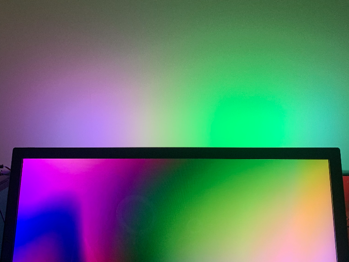
The color of the light follows the screen display, synchronizes the color of screen edge by network, and PICO show the color in real time.

Raspberry Pi - RP2040
x 1
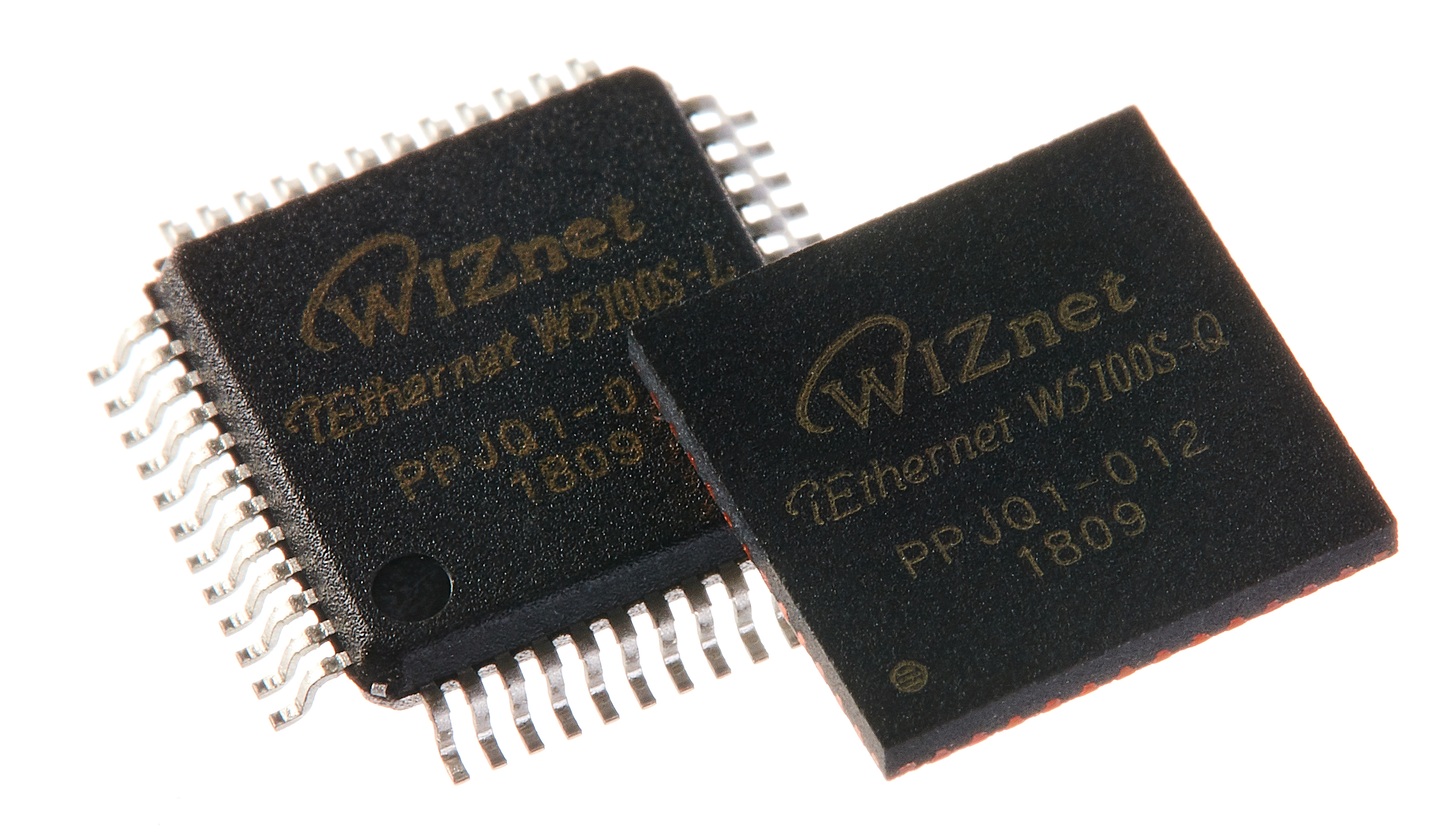
WIZnet - W5100S
x 1

DFRobot - WS2812B LED Strip
x 1

Arduino - Arduino IDE
x 1
Python - Python
x 1
I want to make a screen background light strip, which can change the colour in real time according to the content of the screen display.
According to the planning of the project, we need to develop a program running on the computer side, which can get the colour information of the screen edges, and transfer these colour information to our Ambilight Background Light through the network, and then the Ambilight Background Light's RGB strip will display these colours one by one.
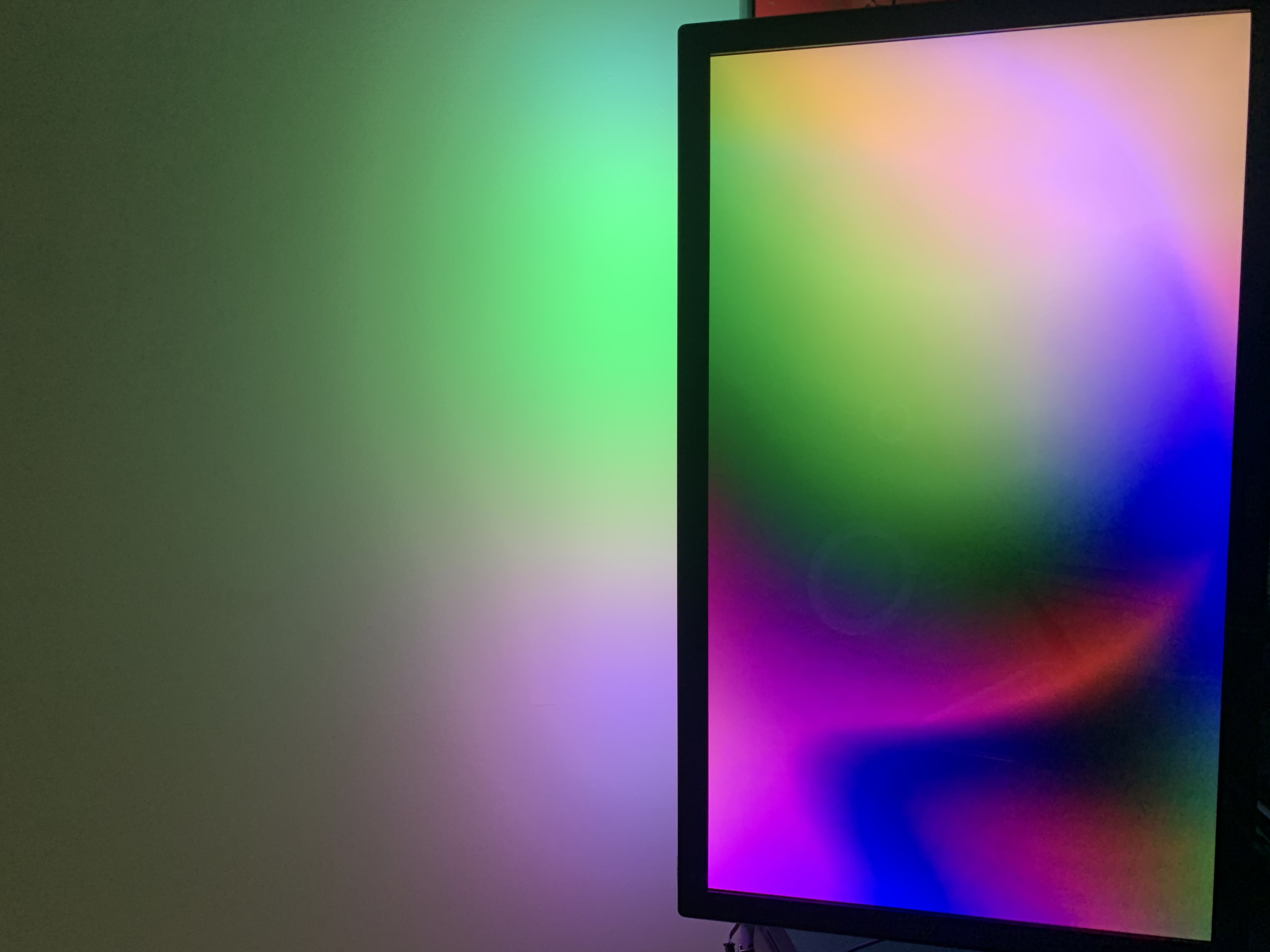
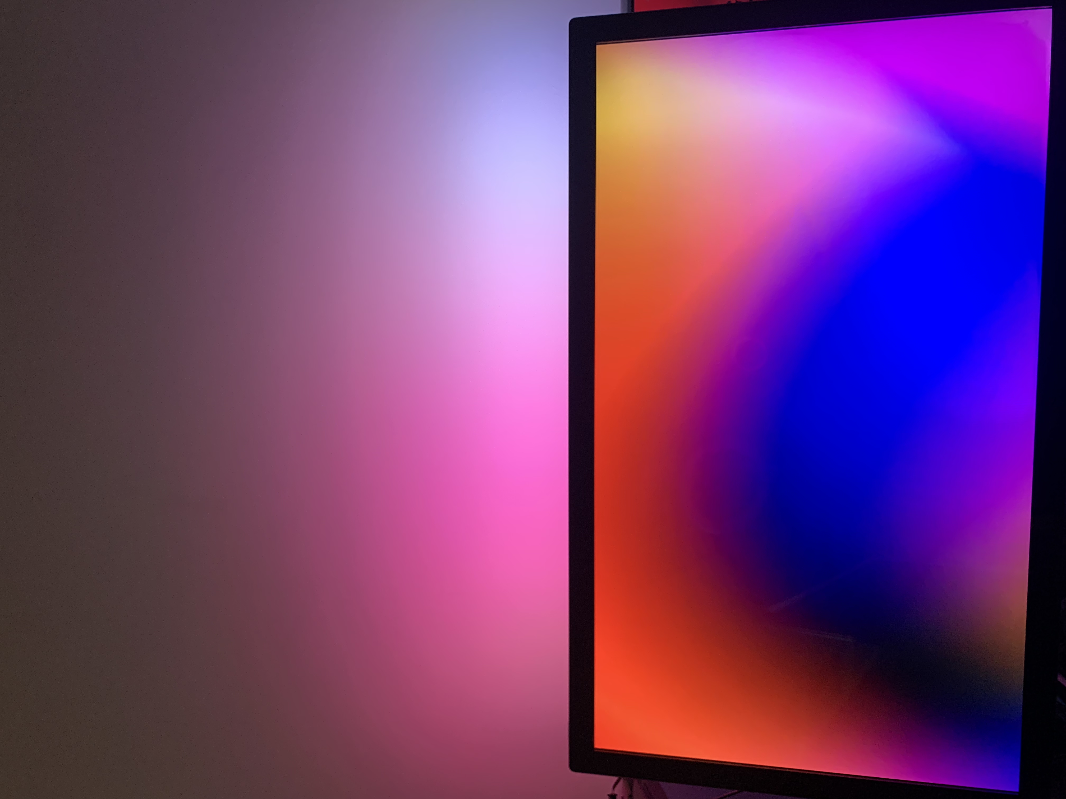
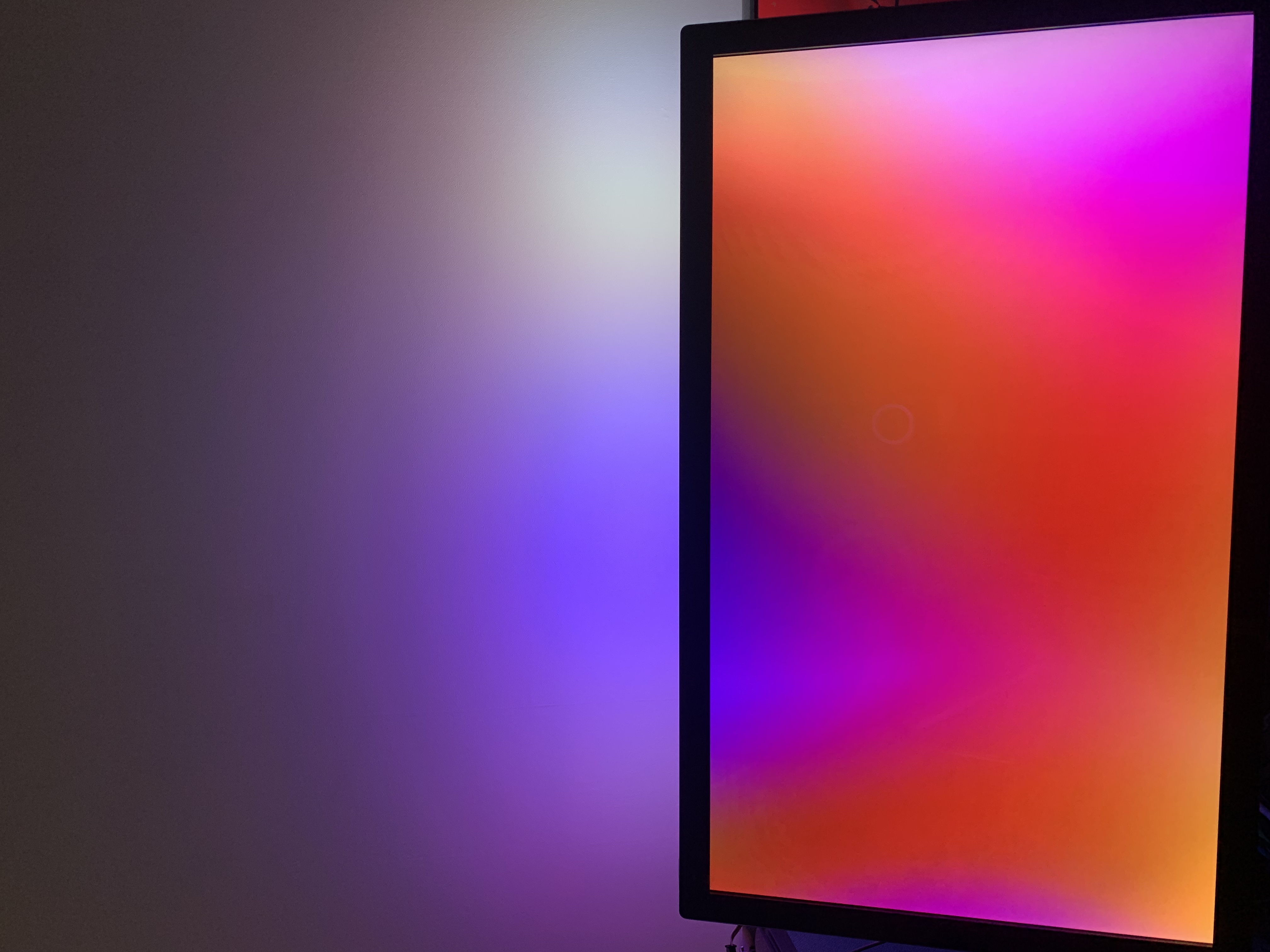
The final result is as follows:
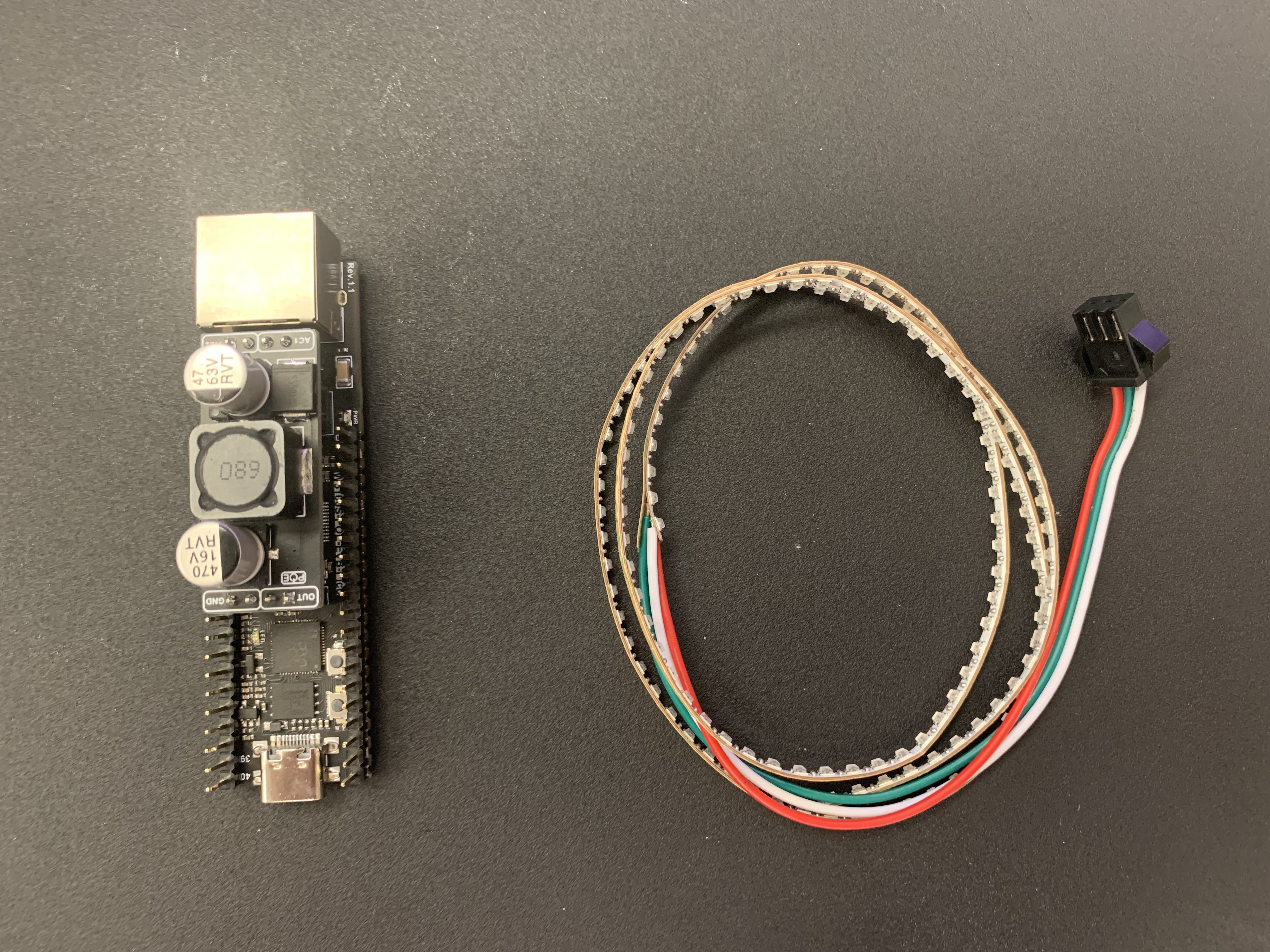
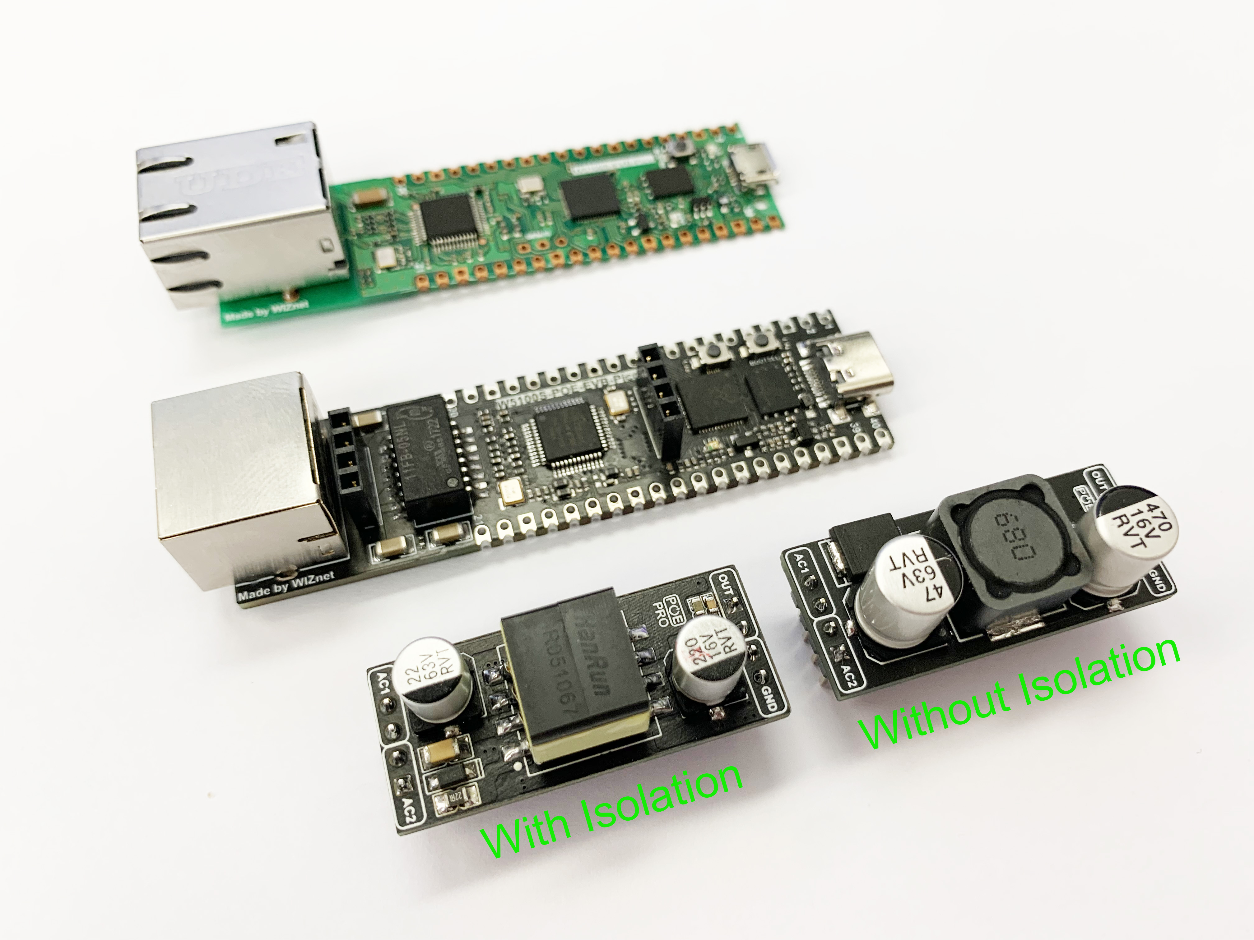
all components used are shown in the figure below.
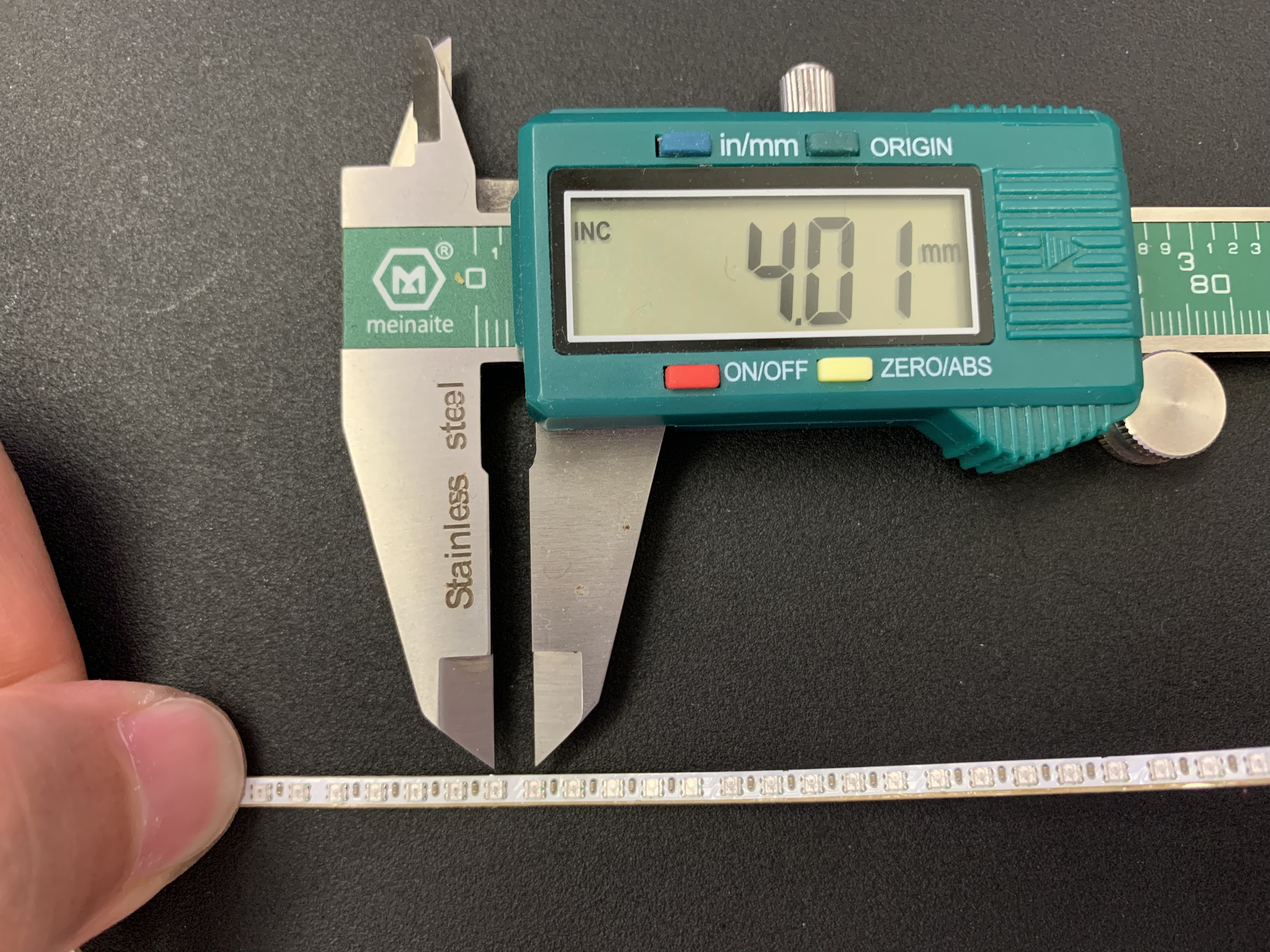
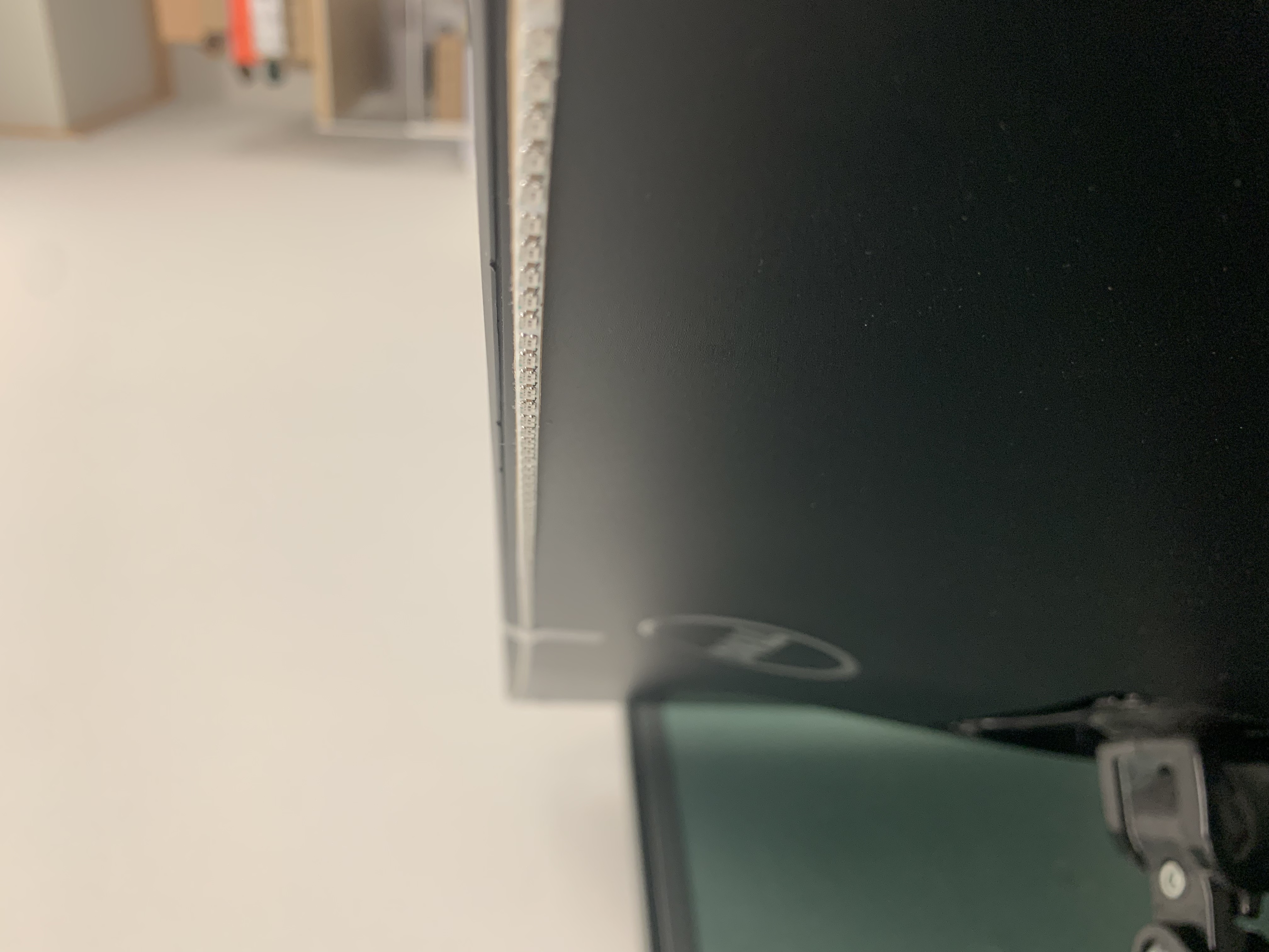
The light strip I used has a very high density of lamp beads. It is 0.6 meters long and has 150 WS2812 lamp beads. On average, there is one WS2812 in the length of 4mm. Choose the highest lamp bead density to achieve the best lighting effect.
Then attach the light strip to the upper edge of the screen.
The main control board I use is W5100S_POE_EVB_PICO, which can be understood as W5100S_EVB_PICO with POE function. The external Pin of both is fully compatible, except that the original Micro USB interface is changed to a Type C interface.
Next let's deal with the Python code running on the PC. I still use ChatGPT to assist in the generated Python code, because I don’t know Python very well, and I just make detailed modifications and logic modifications after ChatGPT generates the code.
STEP 1 , Ask ChatGPT how to get the colours around the edges of the screen;
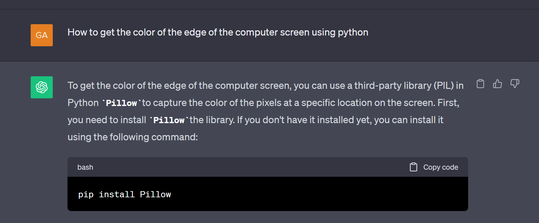
pip install Pillow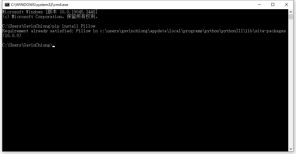
install Pillow finish.
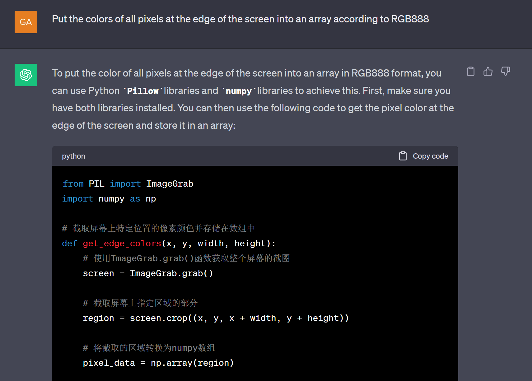
STEP 2 , Put the colors of all pixels at the edge of the screen into an array according to RGB888;
STEP3, The screen resolutions are different, how to automatically match them?
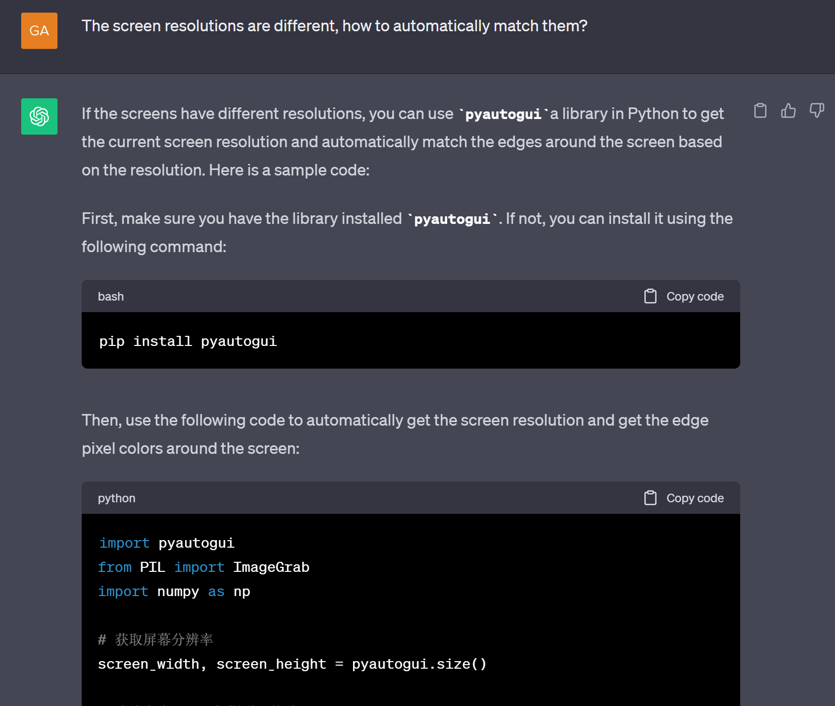
pip install pyautogui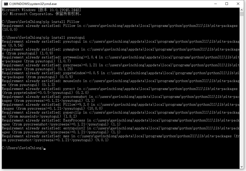
install pyautogui finish.
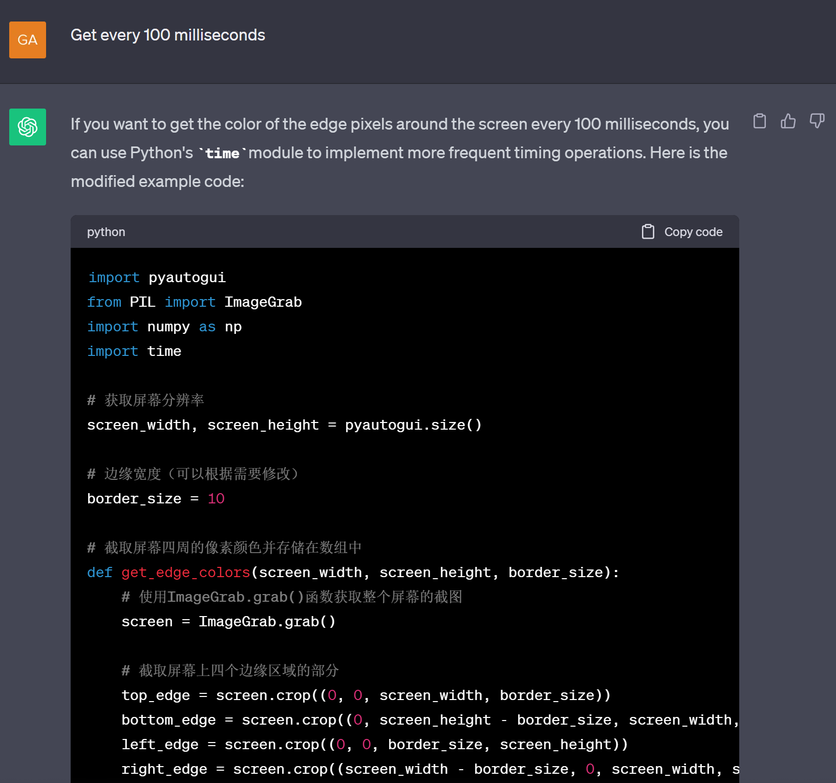
STEP4,Get color data every 100 milliseconds
STEP5, Send the collected data to a tcp server
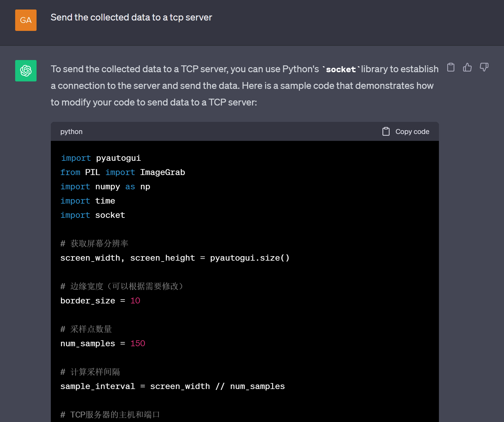
Right now,we got the basic Python code through ChatGPT, and then I modified the code details. After that we got the code that can run completely.
# Import necessary libraries
import pyautogui
from PIL import ImageGrab
import numpy as np
import time
import socket
# Get screen resolution
screen_width, screen_height = pyautogui.size()
# Edge width (adjust as needed)
border_size = 1
# Number of sampling points
num_samples = 150
# Calculate the sampling interval to divide the top edge into num_samples parts
sample_interval = (screen_width // num_samples) + 1
# Host and port of the TCP server
server_host = '10.0.1.227' # Server address
server_port = 5000 # Server port number
# Capture pixel colors from the top edge of the screen and store them in an array
def get_edge_colors(screen_width, screen_height, border_size, num_samples):
# Capture a screenshot of the entire screen using the ImageGrab.grab() function
screen = ImageGrab.grab()
# Crop a portion of the top edge of the screen
top_edge = screen.crop((0, 0, screen_width, border_size))
# Convert the top edge portion to a numpy array
top_edge_pixels = np.array(top_edge)
# Sample a color value from the top edge portion
edge_colors = []
for x in range(0, screen_width, sample_interval):
pixel = top_edge_pixels[0][x]
edge_colors.append(pixel)
return edge_colors
# Create a TCP client socket
client_socket = socket.socket(socket.AF_INET, socket.SOCK_STREAM)
# Connect to the TCP server
client_socket.connect((server_host, server_port))
try:
while True:
edge_colors = get_edge_colors(screen_width, screen_height, border_size, num_samples)
print("screen_width:")
print(screen_width)
print("\r\nnum_samples:")
print(num_samples)
print("\r\nsample_interval:")
print(sample_interval)
# Print the colors of the sampling points
for i, color in enumerate(edge_colors):
print(f"Sample {i + 1}: {color}")
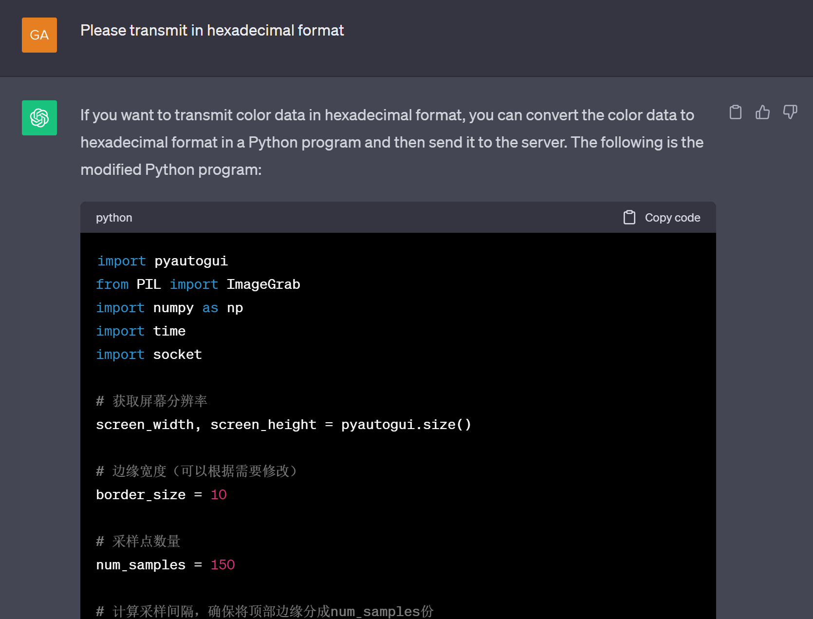
# Convert the data to a hexadecimal string and send it to the server
data_bytes = b"".join([bytes(color) for color in edge_colors])
client_socket.send(data_bytes)
# Sleep for 0.2 seconds (200 milliseconds)
time.sleep(0.2)
except KeyboardInterrupt:
print("Program terminated by the user.")
finally:
# Close the TCP connection
client_socket.close()STEP6, Send the collected data to a tcp server(POE+PICO).
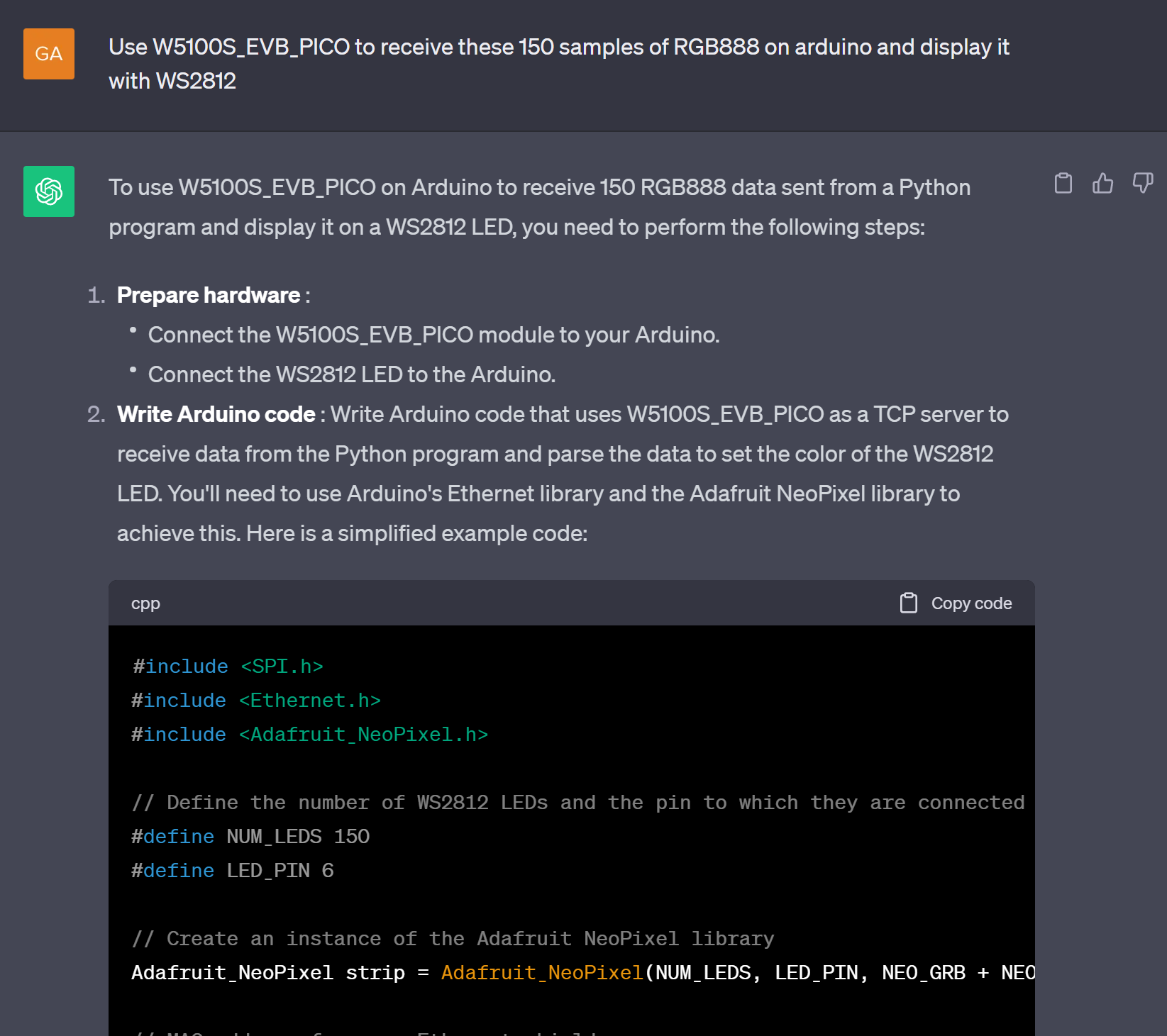
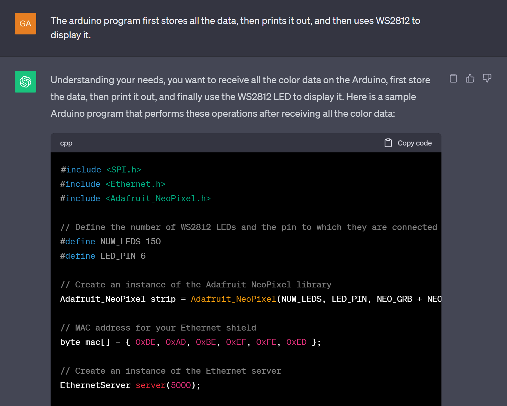
Modify the details so that W5100S_EVB_PICO can smoothly communicate with the Python program running on the PC, obtain the color of the edge of the screen, and display it on 150 WS2812 lamp beads.
void loop() {
  EthernetClient client = server.available();
  if (client) {
    if (client.connected()) {
       while (client.available()) {
        char c = client.read();
        color_char[color_num] = c;
        color_num++;
        Serial.println(color_num);
       }
       if(color_num >= 444)
        {
          color_num =0;
          for (int i = 1; i < NUM_LEDS-1; i++) {
            strip.setPixelColor(i, strip.Color(color_char[i*3], color_char[i*3+1], color_char[i*3+2]));
          }
          strip.show();  // Update all pixels
        }
    }
  }
}
Both the python code and the arduino code are running successfully.
Similar products on the market all use the following technologies.
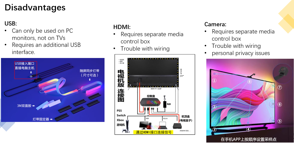
USB HDMI CAMERA and other methods have their shortcomings. If you use the network method, you can avoid those shortcomings and have good effects on both monitors and TVs.
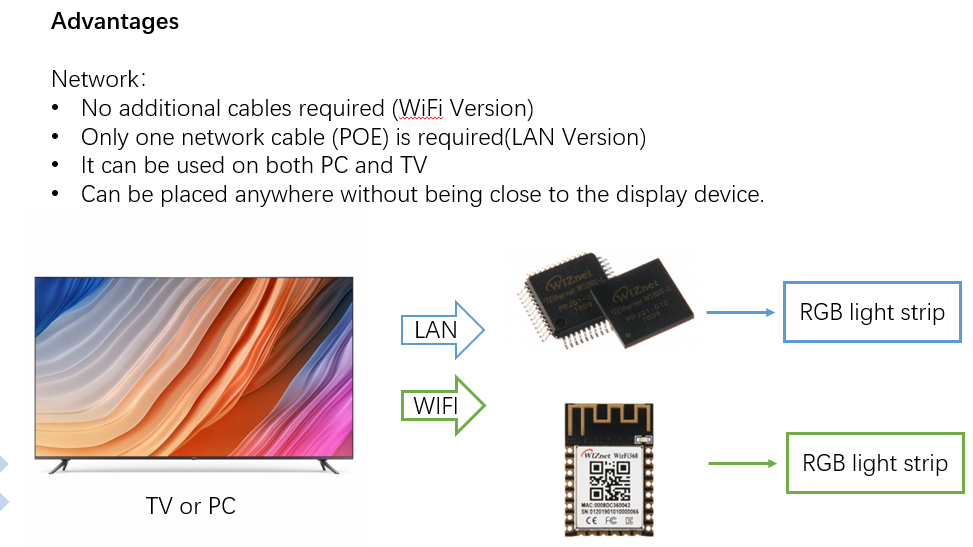
I hope some manufacturers will see this WCC and apply the network to such products.
Done.
-
python and arduino
