



How to Verify a Complete W5500 FPGA Architecture for Robotics?
This educational design describes an Altera FPGA controlling a WIZnet W5500 over SPI for multi-socket UDP communication.
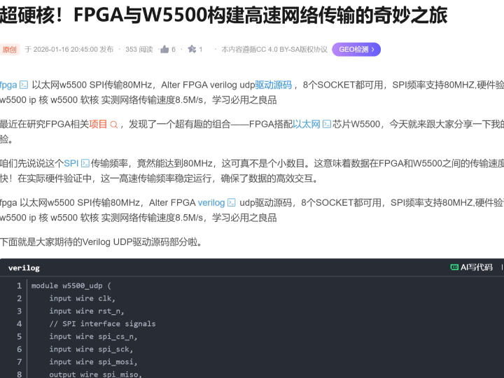
How to Verify a Complete W5500 FPGA Architecture for Robotics?
Summary
This educational design describes an Altera FPGA controlling a WIZnet W5500 over SPI for multi-socket UDP communication. In a robotics system, FPGA logic can collect deterministic sensor or actuator data, schedule traffic across W5500 sockets, and transfer payloads through a shared SPI engine. The W5500 supplies the 10/100 Ethernet MAC, PHY, hardwired TCP/IP processing, eight sockets, and 32 KB packet memory. The source claims an 80 MHz SPI clock and approximately 8.5 MB/s transfer performance, but it does not publish enough test evidence to reproduce those results.
What the Project Does
The source article presents a conceptual FPGA Ethernet design based on the W5500. It describes an Altera-oriented Verilog implementation with support for UDP communication and use of the W5500’s eight hardware sockets.
The visible material includes partial examples of SPI shifting and socket-state control. It does not expose a complete, verifiable RTL project containing all of the following:
- W5500 reset and initialization sequence
- Complete address, control, and data phases for SPI reads and writes
- Per-socket UDP configuration
- TX and RX circular-buffer handling
- Eight-socket arbitration
- Interrupt processing
- Clock and timing constraints
- A complete Quartus project
- Reproducible throughput measurements
The architecture should therefore be treated as an instructional concept rather than a validated robotics communication subsystem.
A complete robotics data path based on the article would be:
Encoders, sensors, cameras, or motor-control logic → FPGA FIFOs → protocol and socket scheduler → W5500 buffer controller → shared SPI master → W5500 UDP sockets → Ethernet network
The receive path would operate in reverse:
Ethernet network → W5500 RX buffers → shared SPI master → socket-specific FPGA FIFOs → command parser → actuator or control logic
A robotics platform could assign sockets according to function:
- Motion command input
- Joint or motor telemetry
- Sensor measurements
- Safety and fault reporting
- Time synchronization
- Configuration
- Diagnostics
- Development or maintenance traffic
The source does not verify these particular assignments. They are a practical extension of the claimed eight-socket structure.
Where WIZnet Fits
The relevant product is the WIZnet W5500. It integrates a 10/100BASE-T Ethernet MAC and PHY, a hardwired TCP/IP engine, eight independent hardware sockets, and 32 KB of configurable TX/RX memory. Its host interface supports SPI modes 0 and 3 at up to 80 MHz.
In this architecture, the W5500 is not merely an external PHY. It handles supported Ethernet and TCP/IP operations, including IPv4, ARP, ICMP, UDP, and TCP socket state. The FPGA accesses control registers and socket buffers rather than implementing the entire protocol stack in programmable logic.
The FPGA remains responsible for:
- Reset and initialization
- SPI transaction generation
- Socket allocation
- UDP destination and port configuration
- TX and RX pointer management
- Circular-buffer wraparound
- Multi-socket arbitration
- Application framing
- Timeout and recovery logic
- Robotics-specific data acquisition and control
This division allows the FPGA to retain deterministic sensor, actuator, and timing logic while reducing the amount of networking RTL that must be designed and verified.
The principal constraint is the shared host interface. Eight sockets are available, but all register and payload traffic crosses one SPI connection. Socket count therefore does not imply eight simultaneous physical data paths.
Implementation Notes
The source article does not provide a complete repository with file paths and line-level RTL that can be verified. No source code is reproduced here. The following architecture identifies the blocks and tests required to turn the article’s concept into a defensible FPGA implementation.
Top-Level Robotics Architecture
A complete design can be divided into these modules:
Robotics interfaces
Capture encoder counts, sensor samples, actuator states, fault inputs, and control-loop data.
Application packetizers
Convert internal signals into UDP payloads with defined headers, lengths, sequence numbers, timestamps, and integrity fields.
Socket-specific FIFOs
Buffer outgoing and incoming traffic independently so that one network channel does not stall another robotics function.
Socket context table
Retain each socket’s mode, ports, destination address, buffer assignment, pending transfer size, timeout, and error state.
Socket scheduler
Select which socket receives access to the shared W5500 controller.
W5500 access controller
Translate logical register and buffer requests into complete W5500 SPI transactions.
SPI master
Generate timing-correct SCLK, MOSI, MISO sampling, and chip-select behavior.
Interrupt and polling controller
Detect received packets, completed sends, socket changes, and link events.
Diagnostics block
Record transfer counts, drops, timeouts, reconnects, buffer pressure, and recovery events.
Complete SPI Transaction Layer
The visible source material is insufficient to establish that its SPI example implements the complete W5500 protocol.
A correct W5500 access contains:
- A 16-bit address offset
- An 8-bit control phase
- One or more data bytes
The control phase selects the W5500 block, read or write direction, and operating mode. Payload transfers should use variable-length burst mode so that the address and control overhead is not repeated for every byte.
The FPGA SPI master should expose a command interface containing:
- Register or buffer address
- Block-select value
- Read or write control
- Transfer length
- TX stream
- RX stream
- Request and completion handshake
- Error and timeout status
The SPI engine should remain in the primary FPGA clock domain where possible. A clock-enable design is generally easier to constrain than using an internally divided SPI signal as an unrelated logic clock.
UDP Transmit Path
A socket’s UDP transmit FSM should perform this sequence:
- Confirm that the socket is open in UDP mode.
- Write or confirm the destination IP address and port.
- Read the available TX-buffer size.
- Wait until enough space is available.
- Read the socket TX write pointer.
- Transfer the payload into W5500 TX memory.
- Split the transfer if it crosses the circular-buffer boundary.
- Update the TX write pointer.
- Issue the SEND command.
- Wait for completion or timeout.
- Clear the relevant interrupt state.
- Return a completion result to the packetizer.
The application packet should include a sequence number. UDP does not retransmit lost datagrams or restore ordering, so the robot controller or receiving application must detect missed, duplicated, or reordered messages when that matters.
UDP Receive Path
A UDP receive FSM should:
- Detect a receive event.
- Read the socket’s received-data size.
- Read the RX pointer.
- Extract the W5500 UDP metadata header.
- Recover the sender IP address, sender port, and payload length.
- Transfer the payload into the socket-specific FPGA FIFO.
- Handle circular-buffer wraparound.
- Update the RX read pointer.
- Issue the receive-complete command.
- Present the packet and metadata to the command parser.
For robotics commands, validation should occur before actuator state changes. The parser can check:
- Expected source address
- Destination function
- Protocol version
- Payload length
- Sequence number
- Timestamp age
- Checksum or application CRC
- Command range and safety state
W5500’s UDP processing does not replace application-level safety validation.
Eight-Socket Scheduling
One SPI engine must serve all sockets. A scheduler is therefore required even though the W5500 maintains the socket states internally.
A robotics-oriented priority policy could be:
- Safety and emergency traffic
- Motion-control commands
- RX servicing near buffer capacity
- Time synchronization
- Joint and motor telemetry
- Sensor streaming
- Diagnostics
- Configuration or maintenance
A fixed-priority scheduler can starve low-priority channels. A weighted round-robin system with urgent-event overrides is usually easier to analyze.
Each scheduler grant should cover one indivisible W5500 transaction. A long payload burst may need a maximum burst size so that high-volume telemetry does not prevent command sockets from receiving service.
Buffer Allocation
The W5500’s 32 KB memory is divided between TX and RX buffers for the eight sockets.
Equal allocation is simple but may not match robotics traffic. For example:
- A command socket may need a small TX buffer and a larger RX buffer.
- A telemetry socket may need a larger TX buffer.
- A diagnostic channel may need minimal capacity.
- A high-rate sensor stream may require the largest continuous allocation.
The allocation must use buffer sizes supported by the W5500. The total configured memory cannot exceed the available TX and RX memory pools.
The FPGA also needs its own FIFOs. W5500 internal memory absorbs network traffic, but it does not remove clock-domain crossing, packet staging, or backpressure requirements inside the FPGA.
Interrupt Processing
The W5500 interrupt output can indicate common and socket events. It should be synchronized before entering the FPGA control domain.
An interrupt controller should:
- Detect the synchronized interrupt.
- Read the common and socket interrupt registers.
- Save pending events.
- Clear only events that have been handled.
- Submit socket-service requests to the scheduler.
- Apply a timeout in case the interrupt line remains asserted.
Polling may still be useful as a recovery mechanism. A missed interrupt must not permanently stop network processing.
Link and Socket Recovery
A mobile or articulated robot can experience cable movement, switch restart, connector vibration, or supply disturbances. Recovery should be state-based rather than relying immediately on a complete FPGA reset.
A suitable hierarchy is:
- Retry the failed W5500 register transaction.
- Close and reopen the affected socket.
- Reapply socket parameters.
- Reinitialize the W5500 after persistent multi-socket failure.
- Reset the complete network subsystem.
- Reset the robot controller only when the fault policy requires it.
Safety-critical actuation must enter a defined state when command traffic becomes stale. Ethernet reconnection should not automatically resume movement without application-level validation.
Performance Verification
The article’s reported 80 MHz SPI operation and approximately 8.5 MB/s network transfer require independent verification.
An 80 MHz single-bit SPI connection has a raw serial ceiling of:
80 Mbit/s ÷ 8 = 10 MB/s
That figure excludes:
- W5500 address and control headers
- Register reads and writes
- Socket pointer updates
- SEND and RECV commands
- Chip-select gaps
- FPGA arbitration
- FIFO stalls
- Network packet headers
- Application headers
- Scheduling among sockets
A reported 8.5 MB/s corresponds to approximately 68 Mbit/s of transferred bytes. It is below the raw 80 Mbit/s SPI ceiling, but reproducing it would require efficient burst transfers and a precise definition of what was counted. The source does not publish enough evidence to determine whether the value represents SPI payload, UDP payload, Ethernet traffic, or another measurement boundary.
A defensible verification plan should include the following.
SPI Physical Timing
Measure with an oscilloscope or logic analyzer:
- Actual SCLK frequency
- Duty cycle
- Setup and hold time
- MOSI transition relative to SCLK
- MISO sampling margin
- Chip-select setup and hold time
- Inter-transaction gaps
- Signal ringing and overshoot
Verify operation across voltage and temperature, not only on one bench setup.
SPI Efficiency
For each test, record:
- Header bytes
- Payload bytes
- Total clock cycles
- Idle cycles
- Transfer length
- Effective payload rate
- FIFO stall time
Calculate:
Effective SPI payload throughput = payload bytes ÷ complete transaction time
Use several payload sizes because small transfers produce much more overhead than long bursts.
UDP Throughput
Generate numbered UDP packets over a sustained interval and record:
- Application payload size
- Packets per second
- Payload throughput
- Ethernet interface rate
- Packet loss
- Duplicates
- Reordering
- FPGA FIFO overflow
- W5500 socket-buffer pressure
- CPU load at the receiving station
The report must distinguish useful robotics payload from UDP, IP, Ethernet, and physical-layer overhead.
Latency and Jitter
Latency is usually more important than peak throughput for command and control.
Use FPGA GPIO markers to identify:
- Command arrival at W5500 interrupt
- Start of SPI read
- Completion of payload transfer
- Command-valid assertion to the robotics controller
- Actuator-update event
Report:
- Minimum latency
- Average latency
- Maximum latency
- Percentiles
- Jitter
- Behavior under simultaneous telemetry traffic
A single average value can hide rare delays that matter to control stability.
Multi-Socket Contention
Run at least these scenarios:
- One active command socket
- One command and one telemetry socket
- All intended production sockets active
- RX-heavy operation
- TX-heavy operation
- Mixed short commands and long telemetry bursts
- Link interruption during peak traffic
Measure whether low-priority bulk traffic delays command handling beyond its deadline.
FPGA Resource and Timing Results
Publish:
- Exact Altera or Intel FPGA device
- Quartus version
- Speed grade
- System clock
- SPI clock
- LUT or adaptive logic module count
- Register count
- Block-memory use
- Maximum timing frequency
- Clock-domain constraints
- Whether debug cores are included
Without this information, resource and speed claims cannot be compared between implementations.
Comparison with an MCU Using ioLibrary
WIZnet ioLibrary is an official C driver package for WIZnet Ethernet chips. It includes W5500 device support, Berkeley-style socket APIs, and application modules.
An MCU architecture is:
Robot sensors and control firmware → MCU application → ioLibrary socket API → MCU SPI peripheral → W5500
An FPGA architecture is:
Robot hardware datapaths → RTL packetizers and socket FSMs → RTL SPI master → W5500
The MCU with ioLibrary provides:
- Simpler socket-state implementation in C
- Easier DHCP, DNS, MQTT, and configuration support
- Faster protocol changes
- More familiar debugging
- Less custom RTL verification
- Straightforward use of maintained WIZnet drivers
The FPGA implementation provides:
- Direct connection to parallel sensor and actuator datapaths
- Deterministic hardware scheduling
- Custom timestamping
- Independent hardware FIFOs
- Precise clock-domain control
- Operation without a software task scheduler
The FPGA version also requires much more custom verification. Socket commands, buffer pointers, SPI framing, timeout behavior, arbitration, and recovery all become RTL responsibilities.
WIZnet’s own published STM32F103 performance example illustrates why implementation details matter. In that test, an STM32F103C8 running at 72 MHz with a 36 MHz SPI clock produced TCP loopback results around 3.5 Mbit/s under the documented configuration, rather than a value inferred directly from the SPI clock. This is not a direct prediction for the FPGA article, but it shows that host architecture, buffer sizes, software overhead, and test methodology materially affect measured throughput.
For an educational robotics platform, an MCU with ioLibrary is usually easier when the objective is to build a functional networked robot. Direct FPGA control is more appropriate when the objective is to study deterministic hardware networking, integrate tightly with existing FPGA datapaths, or eliminate MCU scheduling from the critical data path.
Practical Tips / Pitfalls
- Define the measurement boundary before reporting MB/s or Mbit/s. SPI bytes, UDP payload, Ethernet frames, and useful robotics data are different quantities.
- Limit individual SPI burst lengths so bulk telemetry cannot monopolize the shared interface and delay control commands.
- Test every configured socket-buffer boundary. TX and RX wraparound errors often appear only at particular pointer positions.
- Attach sequence numbers and timestamps to robotics UDP messages so loss, duplication, reordering, and stale commands can be detected.
- Synchronize the W5500 interrupt and use explicit clock-domain-crossing logic for application FIFOs.
- Add bounded timeouts to every SPI, socket, link, SEND, and RECV wait state.
- Fail actuators to a defined safe state when network commands exceed their allowed age; successful Ethernet reconnection alone is not sufficient authorization to resume motion.
FAQ
Q: Why use the W5500 for this FPGA robotics architecture?
The W5500 supplies the Ethernet MAC, PHY, supported TCP/IP protocols, eight sockets, and 32 KB of packet memory. This lets the FPGA focus on sensor interfaces, deterministic scheduling, packet movement, and robot control instead of implementing a complete UDP or TCP/IP stack in RTL.
Q: How does the W5500 connect to the FPGA?
It connects through SPI using SCLK, MOSI, MISO, and chip select. Reset and interrupt signals should also be connected. The W5500 supports SPI modes 0 and 3 at up to 80 MHz, but board-level timing and signal integrity must be verified at the selected rate.
Q: What role does the W5500 play in this robotics project?
It maintains UDP or TCP socket state, stores socket data, handles supported network protocols, and transfers Ethernet traffic through its integrated MAC and PHY. The FPGA configures sockets, schedules SPI access, moves payloads, interprets robotics messages, and applies safety and recovery policies.
Q: Can beginners verify the claimed performance?
A student can measure SPI timing and basic UDP throughput with a logic analyzer, packet capture, and numbered test packets. Reproducing the article’s approximately 8.5 MB/s claim is not possible from the published information alone because the FPGA device, test payload, measurement boundary, RTL, timing report, and traffic conditions are not fully documented.
Q: How does direct FPGA control compare with an MCU using ioLibrary?
An MCU with ioLibrary is easier to implement and maintain because socket handling is expressed through C APIs and official WIZnet drivers. Direct FPGA control can provide tighter timing and closer integration with hardware datapaths, but it requires custom RTL for SPI, socket sequencing, buffer management, arbitration, timeouts, and recovery.
Source
Original article: CSDN article describing an Altera FPGA and W5500 UDP design with eight-socket support, an 80 MHz SPI interface, and a claimed transfer rate near 8.5 MB/s. The visible examples are partial and do not constitute a reproducible complete architecture.
https://blog.csdn.net/2508_94198873/article/details/157028379
WIZnet technical reference: W5500 official datasheet and product documentation covering eight sockets, 32 KB internal memory, supported hardwired protocols, the integrated 10/100 MAC/PHY, and SPI operation up to 80 MHz.
MCU comparison reference: WIZnet ioLibrary Driver, including W5500 support and Berkeley-style socket APIs.
Performance reference: WIZnet’s published SPI performance measurements for an STM32F103-based W5500 test platform. The results are test-specific and are included to illustrate the importance of documenting clocks, buffers, host architecture, and measurement conditions.
License: The source article’s license should be confirmed on the current page before redistribution. No independently downloadable RTL package or separate source-code license was verified from the material reviewed.
Tags
#W5500 #WIZnet #FPGA #AlteraFPGA #Robotics #UDP #SPI #PerformanceVerification #MultiSocket #Ethernet #ioLibrary #EmbeddedNetworking
로보틱스용 W5500 FPGA 전체 아키텍처의 성능을 어떻게 검증할 수 있을까?
요약
이 교육용 설계는 Altera FPGA가 SPI를 통해 WIZnet W5500을 제어하여 다중 소켓 UDP 통신을 수행하는 구조를 설명합니다. 로보틱스 시스템에서 FPGA 로직은 결정론적으로 센서와 액추에이터 데이터를 수집하고, W5500 소켓 간 트래픽을 스케줄링하며, 공유 SPI 엔진을 통해 페이로드를 전송할 수 있습니다. W5500은 10/100 이더넷 MAC, PHY, 하드와이어드 TCP/IP 처리, 8개의 소켓, 32 KB 패킷 메모리를 제공합니다. 원문은 80 MHz SPI와 약 8.5 MB/s 전송 성능을 주장하지만, 이를 재현할 수 있는 충분한 시험 자료는 제공하지 않습니다.
프로젝트가 하는 일
원문은 W5500을 기반으로 한 개념적인 FPGA 이더넷 설계를 소개합니다. Altera FPGA용 Verilog 구현을 설명하며, UDP 통신과 W5500의 8개 하드웨어 소켓 사용을 지원한다고 주장합니다.
공개된 자료에는 SPI 시프트 동작과 소켓 상태 제어의 일부 예제가 포함되어 있습니다. 그러나 다음 항목을 모두 포함하는 완전하고 검증 가능한 RTL 프로젝트는 제공되지 않습니다.
W5500 리셋 및 초기화 시퀀스
SPI 읽기와 쓰기를 위한 전체 주소, 제어, 데이터 단계
소켓별 UDP 설정
TX/RX 원형 버퍼 처리
8개 소켓 중재
인터럽트 처리
클럭 및 타이밍 제약
완전한 Quartus 프로젝트
재현 가능한 처리량 측정
따라서 이 아키텍처는 검증된 로보틱스 통신 서브시스템이 아니라 교육용 개념으로 다루어야 합니다.
원문을 기반으로 구성할 수 있는 완전한 로보틱스 데이터 경로는 다음과 같습니다.
엔코더, 센서, 카메라 또는 모터 제어 로직 → FPGA FIFO → 프로토콜 및 소켓 스케줄러 → W5500 버퍼 컨트롤러 → 공유 SPI 마스터 → W5500 UDP 소켓 → 이더넷 네트워크
수신 경로는 반대 방향으로 동작합니다.
이더넷 네트워크 → W5500 RX 버퍼 → 공유 SPI 마스터 → 소켓별 FPGA FIFO → 명령 파서 → 액추에이터 또는 제어 로직
로봇 플랫폼에서는 소켓을 다음과 같이 배정할 수 있습니다.
모션 명령 입력
관절 또는 모터 텔레메트리
센서 측정값
안전 및 오류 보고
시간 동기화
설정
진단
개발 또는 유지보수 트래픽
이러한 소켓 배정은 원문에서 검증된 것이 아니라, 8개 소켓 구조를 실제 로봇 시스템에 적용한 아키텍처 확장안입니다.
WIZnet이 적용되는 위치
사용되는 제품은 WIZnet W5500입니다. W5500은 10/100BASE-T 이더넷 MAC과 PHY, 하드와이어드 TCP/IP 엔진, 8개의 독립적인 하드웨어 소켓, 32 KB의 설정 가능한 TX/RX 메모리를 통합합니다. 호스트 인터페이스는 SPI 모드 0과 모드 3을 지원하며 최대 80 MHz로 동작합니다.
이 아키텍처에서 W5500은 단순한 외부 PHY가 아닙니다. IPv4, ARP, ICMP, UDP, TCP 소켓 상태를 포함한 지원 네트워크 처리를 수행합니다. FPGA는 전체 프로토콜 스택을 프로그래머블 로직에 구현하는 대신 W5500의 제어 레지스터와 소켓 버퍼에 접근합니다.
FPGA는 다음 기능을 담당합니다.
리셋 및 초기화
SPI 트랜잭션 생성
소켓 할당
UDP 목적지 주소와 포트 설정
TX/RX 포인터 관리
원형 버퍼 래핑 처리
다중 소켓 중재
애플리케이션 프레이밍
타임아웃 및 복구 로직
로보틱스 전용 데이터 수집과 제어
이 역할 분담은 FPGA가 결정론적인 센서, 액추에이터, 타이밍 로직을 유지하면서도 네트워크 RTL의 구현 범위를 줄이는 데 유용합니다.
주요 제약은 공유 호스트 인터페이스입니다. 8개의 소켓이 제공되지만 모든 레지스터와 페이로드 트래픽은 하나의 SPI 연결을 통과합니다. 따라서 소켓 수가 8개라는 것은 8개의 독립적인 물리 데이터 경로가 동시에 존재한다는 의미가 아닙니다.
구현 참고 사항
원문은 파일 경로와 코드 라인을 검증할 수 있는 완전한 저장소를 제공하지 않습니다. 따라서 실제 코드는 인용하지 않습니다. 아래 구조는 원문의 개념을 방어 가능한 FPGA 구현으로 발전시키기 위해 필요한 블록과 시험 항목을 정리한 것입니다.
최상위 로보틱스 아키텍처
완전한 설계는 다음 모듈로 나눌 수 있습니다.
로보틱스 인터페이스
엔코더 카운트, 센서 샘플, 액추에이터 상태, 오류 입력, 제어 루프 데이터를 수집합니다.
애플리케이션 패킷 생성기
내부 신호를 정의된 헤더, 길이, 시퀀스 번호, 타임스탬프, 무결성 필드를 포함한 UDP 페이로드로 변환합니다.
소켓별 FIFO
송신 및 수신 트래픽을 독립적으로 버퍼링하여 하나의 네트워크 채널이 다른 로봇 기능을 막지 않도록 합니다.
소켓 컨텍스트 테이블
각 소켓의 모드, 포트, 목적지 주소, 버퍼 할당, 대기 중인 전송 크기, 타임아웃, 오류 상태를 유지합니다.
소켓 스케줄러
어떤 소켓이 공유 W5500 컨트롤러를 사용할지 결정합니다.
W5500 접근 컨트롤러
논리적인 레지스터 및 버퍼 요청을 완전한 W5500 SPI 트랜잭션으로 변환합니다.
SPI 마스터
타이밍이 보장된 SCLK, MOSI, MISO 샘플링, 칩 선택 동작을 생성합니다.
인터럽트 및 폴링 컨트롤러
수신 패킷, 송신 완료, 소켓 변화, 링크 이벤트를 감지합니다.
진단 블록
전송 횟수, 드롭, 타임아웃, 재연결, 버퍼 압력, 복구 이벤트를 기록합니다.
완전한 SPI 트랜잭션 계층
원문에 공개된 예제만으로는 완전한 W5500 SPI 프로토콜이 구현되었다고 판단할 수 없습니다.
올바른 W5500 접근은 다음 요소로 구성됩니다.
16비트 주소 오프셋
8비트 제어 단계
하나 이상의 데이터 바이트
제어 단계는 W5500 블록, 읽기 또는 쓰기 방향, 동작 모드를 선택합니다. 페이로드 전송에서는 매 바이트마다 주소와 제어 오버헤드를 반복하지 않도록 가변 길이 버스트 모드를 사용해야 합니다.
FPGA SPI 마스터는 다음 명령 인터페이스를 제공하는 것이 좋습니다.
레지스터 또는 버퍼 주소
블록 선택 값
읽기 또는 쓰기 제어
전송 길이
TX 스트림
RX 스트림
요청 및 완료 핸드셰이크
오류와 타임아웃 상태
가능하면 SPI 엔진은 FPGA의 주 클럭 도메인 안에서 동작해야 합니다. 내부에서 분주한 SPI 신호를 별도 로직 클럭처럼 사용하는 것보다 clock enable 방식이 타이밍 제약과 검증에 유리합니다.
UDP 송신 경로
소켓의 UDP 송신 FSM은 다음 순서로 동작해야 합니다.
소켓이 UDP 모드로 열려 있는지 확인합니다.
목적지 IP 주소와 포트를 설정하거나 검증합니다.
사용 가능한 TX 버퍼 크기를 읽습니다.
충분한 공간이 생길 때까지 기다립니다.
소켓 TX 쓰기 포인터를 읽습니다.
페이로드를 W5500 TX 메모리에 전송합니다.
전송이 원형 버퍼 경계를 넘으면 분할 처리합니다.
TX 쓰기 포인터를 갱신합니다.
SEND 명령을 실행합니다.
완료 또는 타임아웃을 기다립니다.
관련 인터럽트 상태를 지웁니다.
패킷 생성기에 완료 결과를 반환합니다.
애플리케이션 패킷에는 시퀀스 번호를 포함하는 것이 좋습니다. UDP는 손실된 데이터그램을 재전송하거나 순서를 복원하지 않으므로, 필요하다면 로봇 컨트롤러나 수신 애플리케이션이 누락, 중복, 순서 변경을 감지해야 합니다.
UDP 수신 경로
UDP 수신 FSM은 다음 순서를 수행해야 합니다.
수신 이벤트를 감지합니다.
소켓의 수신 데이터 크기를 읽습니다.
RX 포인터를 읽습니다.
W5500 UDP 메타데이터 헤더를 추출합니다.
송신자 IP 주소, 송신자 포트, 페이로드 길이를 복구합니다.
페이로드를 소켓별 FPGA FIFO로 전송합니다.
원형 버퍼 래핑을 처리합니다.
RX 읽기 포인터를 갱신합니다.
수신 완료 명령을 실행합니다.
패킷과 메타데이터를 명령 파서에 전달합니다.
로봇 명령은 액추에이터 상태를 변경하기 전에 반드시 검증해야 합니다. 파서는 다음 항목을 확인할 수 있습니다.
예상된 송신자 주소
목적지 기능
프로토콜 버전
페이로드 길이
시퀀스 번호
타임스탬프의 유효 시간
체크섬 또는 애플리케이션 CRC
명령 범위와 안전 상태
W5500의 UDP 처리가 애플리케이션 수준의 안전 검증을 대신하지는 않습니다.
8개 소켓 스케줄링
W5500이 소켓 상태를 내부적으로 관리하더라도, 하나의 SPI 엔진이 모든 소켓을 처리하므로 스케줄러가 필요합니다.
로보틱스용 우선순위 정책은 다음과 같이 구성할 수 있습니다.
안전 및 비상 트래픽
모션 제어 명령
버퍼 용량 한계에 가까운 RX 처리
시간 동기화
관절 및 모터 텔레메트리
센서 스트리밍
진단
설정 또는 유지보수
고정 우선순위 방식은 낮은 우선순위 채널을 장시간 굶길 수 있습니다. 긴급 이벤트 우선 처리 기능을 포함한 가중 라운드 로빈 방식이 분석하기 쉬울 수 있습니다.
각 스케줄러 grant는 하나의 완전한 W5500 트랜잭션 동안 유지되어야 합니다. 긴 페이로드 버스트에는 최대 길이를 설정하여 대용량 텔레메트리가 명령 소켓의 서비스를 지나치게 지연하지 않도록 해야 합니다.
버퍼 할당
W5500의 32 KB 메모리는 8개 소켓의 TX 및 RX 버퍼로 나뉩니다.
동일하게 배분하면 단순하지만 로보틱스 트래픽 특성과 맞지 않을 수 있습니다.
명령 소켓은 작은 TX 버퍼와 큰 RX 버퍼가 필요할 수 있습니다.
텔레메트리 소켓은 큰 TX 버퍼가 필요할 수 있습니다.
진단 채널은 최소한의 용량으로 충분할 수 있습니다.
고속 센서 스트림은 가장 큰 연속 버퍼가 필요할 수 있습니다.
버퍼 크기는 W5500이 지원하는 설정값을 사용해야 하며, 전체 할당량은 TX 및 RX 메모리 풀을 초과할 수 없습니다.
FPGA 내부에도 별도의 FIFO가 필요합니다. W5500 내부 메모리가 네트워크 패킷을 저장하지만 FPGA 내부의 클럭 도메인 교차, 패킷 스테이징, 백프레셔 처리를 제거해 주지는 않습니다.
인터럽트 처리
W5500 인터럽트 출력은 공통 이벤트와 소켓 이벤트를 알릴 수 있습니다. FPGA 제어 도메인에 들어가기 전에 반드시 동기화해야 합니다.
인터럽트 컨트롤러는 다음과 같이 동작할 수 있습니다.
동기화된 인터럽트를 감지합니다.
공통 및 소켓 인터럽트 레지스터를 읽습니다.
처리 대기 이벤트를 저장합니다.
실제로 처리한 이벤트만 지웁니다.
소켓 서비스 요청을 스케줄러에 제출합니다.
인터럽트 라인이 계속 활성화된 경우를 대비해 타임아웃을 적용합니다.
인터럽트 누락에 대비해 복구용 폴링을 함께 사용하는 것도 유용합니다. 하나의 인터럽트 누락이 전체 네트워크 처리를 영구적으로 중단해서는 안 됩니다.
링크 및 소켓 복구
이동형 또는 관절형 로봇에서는 케이블 움직임, 스위치 재시작, 커넥터 진동, 전원 변동이 발생할 수 있습니다. 복구는 즉시 전체 FPGA를 리셋하는 방식이 아니라 상태 기반으로 수행해야 합니다.
권장 복구 단계는 다음과 같습니다.
실패한 W5500 레지스터 트랜잭션을 재시도합니다.
영향을 받은 소켓을 닫고 다시 엽니다.
소켓 설정값을 다시 적용합니다.
여러 소켓에서 지속적인 오류가 발생하면 W5500을 재초기화합니다.
네트워크 서브시스템 전체를 재시작합니다.
오류 정책상 필요한 경우에만 로봇 컨트롤러 전체를 리셋합니다.
명령 트래픽이 오래된 경우 안전 관련 액추에이터는 정의된 상태로 전환되어야 합니다. 이더넷 연결이 복구되었다는 이유만으로 애플리케이션 수준의 검증 없이 자동으로 동작을 재개해서는 안 됩니다.
성능 검증
원문에서 주장한 80 MHz SPI와 약 8.5 MB/s 네트워크 전송 성능은 독립적으로 검증해야 합니다.
80 MHz 단일 비트 SPI 연결의 이론적 직렬 한계는 다음과 같습니다.
80 Mbit/s ÷ 8 = 10 MB/s
이 값에는 다음 오버헤드가 포함되지 않습니다.
W5500 주소 및 제어 헤더
레지스터 읽기와 쓰기
소켓 포인터 갱신
SEND 및 RECV 명령
칩 선택 간 공백
FPGA 중재
FIFO 대기
네트워크 패킷 헤더
애플리케이션 헤더
소켓 간 스케줄링
8.5 MB/s는 약 68 Mbit/s에 해당합니다. 이는 이론적인 80 Mbit/s SPI 상한보다 낮기 때문에 물리적으로 불가능한 값은 아니지만, 이를 재현하려면 효율적인 버스트 전송과 명확한 측정 기준이 필요합니다.
원문에는 해당 값이 SPI 페이로드인지, UDP 페이로드인지, 이더넷 트래픽인지, 다른 측정 구간인지 판단할 수 있는 자료가 충분하지 않습니다.
신뢰할 수 있는 검증 계획은 다음 항목을 포함해야 합니다.
SPI 물리 타이밍
오실로스코프나 로직 분석기로 다음 항목을 측정합니다.
실제 SCLK 주파수
듀티비
setup 및 hold 시간
SCLK에 대한 MOSI 전이 시점
MISO 샘플링 여유
칩 선택 setup 및 hold 시간
트랜잭션 간 공백
신호 링잉과 오버슈트
한 번의 벤치 시험만으로 끝내지 말고 전압과 온도 범위에서 검증해야 합니다.
SPI 효율
각 시험에서 다음을 기록합니다.
헤더 바이트 수
페이로드 바이트 수
전체 클럭 수
유휴 클럭 수
전송 길이
유효 페이로드 속도
FIFO stall 시간
계산식은 다음과 같습니다.
유효 SPI 페이로드 처리량 = 페이로드 바이트 수 ÷ 전체 트랜잭션 시간
작은 전송은 긴 버스트보다 오버헤드 비율이 크므로 여러 페이로드 크기로 시험해야 합니다.
UDP 처리량
일정 시간 동안 시퀀스 번호가 포함된 UDP 패킷을 전송하고 다음을 기록합니다.
애플리케이션 페이로드 크기
초당 패킷 수
페이로드 처리량
이더넷 인터페이스 속도
패킷 손실
중복
순서 변경
FPGA FIFO 오버플로
W5500 소켓 버퍼 압력
수신 장치의 CPU 부하
보고서에서는 실제 로보틱스 페이로드와 UDP, IP, 이더넷, 물리 계층 오버헤드를 구분해야 합니다.
지연시간과 지터
명령 및 제어에서는 최대 처리량보다 지연시간이 더 중요할 수 있습니다.
FPGA GPIO 마커를 사용해 다음 시점을 측정할 수 있습니다.
W5500 인터럽트에서 명령 도착 감지
SPI 읽기 시작
페이로드 전송 완료
로봇 제어기로 command-valid 신호 출력
액추에이터 갱신 이벤트
다음 값을 보고해야 합니다.
최소 지연
평균 지연
최대 지연
백분위수
지터
동시 텔레메트리 트래픽에서의 동작
평균값 하나만 제시하면 제어 안정성에 영향을 줄 수 있는 드문 지연을 숨길 수 있습니다.
다중 소켓 경합
최소한 다음 시나리오를 시험해야 합니다.
명령 소켓 1개만 활성화
명령 소켓과 텔레메트리 소켓 동시 활성화
실제 제품에서 사용할 모든 소켓 활성화
RX 중심 동작
TX 중심 동작
짧은 명령과 긴 텔레메트리 버스트 혼합
최대 트래픽 중 링크 단절
낮은 우선순위의 대용량 트래픽이 명령 처리 지연을 허용 범위 이상으로 증가시키는지 확인해야 합니다.
FPGA 자원 및 타이밍 결과
다음 정보를 공개해야 합니다.
정확한 Altera 또는 Intel FPGA 디바이스
Quartus 버전
속도 등급
시스템 클럭
SPI 클럭
LUT 또는 ALM 수
레지스터 수
블록 메모리 사용량
달성된 최대 동작 주파수
클럭 도메인 제약
디버그 코어 포함 여부
이 정보가 없으면 서로 다른 구현의 자원 사용량과 속도 주장을 비교할 수 없습니다.
MCU와 ioLibrary를 사용하는 방식과 비교
WIZnet ioLibrary는 WIZnet 이더넷 칩용 공식 C 드라이버 패키지입니다. W5500 장치 지원, Berkeley 스타일 소켓 API, 애플리케이션 모듈을 포함합니다.
MCU 구조는 다음과 같습니다.
로봇 센서 및 제어 펌웨어 → MCU 애플리케이션 → ioLibrary 소켓 API → MCU SPI 주변장치 → W5500
FPGA 구조는 다음과 같습니다.
로봇 하드웨어 데이터 경로 → RTL 패킷 생성기 및 소켓 FSM → RTL SPI 마스터 → W5500
MCU와 ioLibrary 조합의 장점은 다음과 같습니다.
C 언어로 소켓 상태를 구현하기 쉬움
DHCP, DNS, MQTT, 설정 기능 구현이 쉬움
프로토콜 변경이 빠름
일반적인 디버깅 환경
사용자 정의 RTL 검증 부담 감소
유지보수되는 WIZnet 드라이버 활용 가능
FPGA 구현의 장점은 다음과 같습니다.
병렬 센서 및 액추에이터 데이터 경로와 직접 연결
결정론적인 하드웨어 스케줄링
사용자 정의 타임스탬프 처리
독립적인 하드웨어 FIFO
정밀한 클럭 도메인 제어
소프트웨어 태스크 스케줄러 없이 동작
그러나 FPGA 방식은 더 많은 사용자 정의 검증이 필요합니다. 소켓 명령, 버퍼 포인터, SPI 프레이밍, 타임아웃, 중재, 복구가 모두 RTL 책임이 됩니다.
WIZnet이 공개한 STM32F103 기반 성능 예제는 구현 방식이 결과에 큰 영향을 준다는 점을 보여줍니다. 해당 시험에서는 72 MHz STM32F103C8과 36 MHz SPI를 사용해 약 3.5 Mbit/s의 TCP 루프백 결과가 보고되었습니다.
이 수치는 FPGA 원문의 성능을 직접 예측하는 값은 아닙니다. 다만 호스트 구조, 버퍼 크기, 소프트웨어 오버헤드, 시험 방법이 실제 처리량에 큰 영향을 준다는 점을 보여줍니다.
교육용 로보틱스 플랫폼에서 목표가 실제 네트워크 로봇을 빠르게 구현하는 것이라면 MCU와 ioLibrary가 일반적으로 더 쉽습니다.
반대로 결정론적인 하드웨어 네트워킹을 학습하거나, 기존 FPGA 데이터 경로와 밀접하게 결합하거나, 핵심 데이터 경로에서 MCU 스케줄링을 제거하려는 경우에는 직접 FPGA 제어가 더 적합합니다.
실무 팁과 주의사항
MB/s 또는 Mbit/s를 보고하기 전에 측정 구간을 정의해야 합니다. SPI 바이트, UDP 페이로드, 이더넷 프레임, 실제 로봇 데이터는 서로 다른 값입니다.
대용량 텔레메트리가 공유 SPI 인터페이스를 장시간 점유하지 않도록 개별 SPI 버스트의 최대 길이를 제한해야 합니다.
설정한 모든 소켓 버퍼 경계를 시험해야 합니다. TX/RX 래핑 오류는 특정 포인터 위치에서만 나타날 수 있습니다.
로보틱스 UDP 메시지에 시퀀스 번호와 타임스탬프를 포함해 손실, 중복, 순서 변경, 오래된 명령을 감지해야 합니다.
W5500 인터럽트를 동기화하고, 애플리케이션 FIFO에는 명시적인 클럭 도메인 교차 로직을 적용해야 합니다.
모든 SPI, 소켓, 링크, SEND, RECV 대기 상태에 제한된 타임아웃을 추가해야 합니다.
네트워크 명령이 허용된 시간보다 오래되면 액추에이터를 정의된 안전 상태로 전환해야 합니다. 이더넷 연결 복구만으로 움직임 재개를 허용해서는 안 됩니다.
FAQ
Q: 이 FPGA 로보틱스 아키텍처에서 W5500을 사용하는 이유는 무엇인가요?
W5500은 이더넷 MAC, PHY, 지원되는 TCP/IP 프로토콜, 8개의 소켓, 32 KB 패킷 메모리를 제공합니다. 이를 통해 FPGA는 전체 UDP 또는 TCP/IP 스택을 RTL로 구현하지 않고도 센서 인터페이스, 결정론적인 스케줄링, 패킷 이동, 로봇 제어에 집중할 수 있습니다.
Q: W5500은 FPGA와 어떻게 연결하나요?
SCLK, MOSI, MISO, 칩 선택 신호를 사용하는 SPI로 연결합니다. RESET과 INT 신호도 함께 연결해야 합니다. W5500은 SPI 모드 0과 모드 3에서 최대 80 MHz를 지원하지만, 선택한 속도에서 보드 수준의 타이밍과 신호 무결성을 검증해야 합니다.
Q: 이 로보틱스 프로젝트에서 W5500은 어떤 역할을 하나요?
W5500은 UDP 또는 TCP 소켓 상태를 유지하고, 소켓 데이터를 저장하며, 지원되는 네트워크 프로토콜을 처리하고, 통합 MAC과 PHY를 통해 이더넷 트래픽을 전달합니다. FPGA는 소켓 설정, SPI 접근 스케줄링, 페이로드 전송, 로봇 메시지 해석, 안전 및 복구 정책을 담당합니다.
Q: 초보자도 원문에서 주장한 성능을 검증할 수 있나요?
학생도 로직 분석기, 패킷 캡처, 시퀀스 번호가 포함된 시험 패킷을 사용해 SPI 타이밍과 기본 UDP 처리량을 측정할 수 있습니다. 하지만 약 8.5 MB/s라는 원문의 주장은 FPGA 디바이스, 시험 페이로드, 측정 구간, RTL, 타이밍 보고서, 트래픽 조건이 충분히 공개되지 않았기 때문에 현재 정보만으로는 재현할 수 없습니다.
Q: 직접 FPGA 제어는 MCU와 ioLibrary를 사용하는 방식과 어떻게 다른가요?
MCU와 ioLibrary를 사용하면 C API와 공식 WIZnet 드라이버를 통해 소켓을 구현할 수 있어 개발과 유지보수가 쉽습니다. 직접 FPGA 제어는 더 정밀한 타이밍과 하드웨어 데이터 경로 통합을 제공할 수 있지만, SPI, 소켓 시퀀스, 버퍼 관리, 중재, 타임아웃, 복구를 위한 사용자 정의 RTL이 필요합니다.
출처
원문: Altera FPGA와 W5500을 이용한 UDP 설계를 설명하는 CSDN 글
https://blog.csdn.net/2508_94198873/article/details/157028379
원문은 8개 소켓 지원, 80 MHz SPI, 약 8.5 MB/s 전송 성능을 주장합니다. 공개된 예제는 일부만 제공되며, 재현 가능한 완전한 아키텍처를 구성하지는 않습니다.
WIZnet 기술 참고 자료: W5500 공식 데이터시트 및 제품 문서
https://docs.wiznet.io/Product/Chip/Ethernet/W5500
8개 소켓, 32 KB 내부 메모리, 지원되는 하드와이어드 프로토콜, 통합 10/100 MAC/PHY, 최대 80 MHz SPI 동작을 설명합니다.
MCU 비교 참고 자료: WIZnet ioLibrary Driver
https://github.com/Wiznet/ioLibrary_Driver
W5500 지원과 Berkeley 스타일 소켓 API를 제공합니다.
성능 참고 자료: WIZnet STM32F103 기반 W5500 SPI 성능 시험 문서
https://docs.wiznet.io/Product/Chip/Ethernet/W5500/Application/spi-performance
이 결과는 특정 시험 환경에 대한 값이며, 클럭, 버퍼, 호스트 구조, 측정 조건을 문서화해야 하는 이유를 보여주는 참고 자료입니다.
라이선스: 원문의 라이선스는 재배포 전에 현재 페이지에서 확인해야 합니다. 검토한 자료에서는 별도의 다운로드 가능한 RTL 패키지나 독립적인 소스 코드 라이선스를 확인하지 못했습니다.
태그
#W5500 #WIZnet #FPGA #AlteraFPGA #Robotics #UDP #SPI #PerformanceVerification #MultiSocket #Ethernet #ioLibrary #EmbeddedNetworking