



How to Build an Industrial FPGA Network Stack with WIZnet W5500 on Verilog?
This Industrial IoT project uses Verilog FPGA logic to control a WIZnet W5500 through an 80 MHz SPI interface.
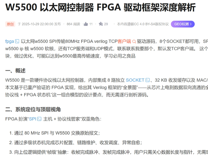
How to Build an Industrial FPGA Network Stack with WIZnet W5500 on Verilog?
Summary
This Industrial IoT project uses Verilog FPGA logic to control a WIZnet W5500 through an 80 MHz SPI interface. The FPGA implements initialization, socket scheduling, event handling, data movement, and fault-recovery state machines, while W5500 provides the 10/100 Ethernet MAC/PHY, hardwired IPv4 TCP/IP processing, eight hardware sockets, and 32 KB of packet memory. The architecture is suitable for deterministic data acquisition, industrial control gateways, machine monitoring, and multi-channel telemetry where the FPGA must retain direct control over network timing and payload flow. The source article describes a production-tested implementation but does not expose inspectable HDL or a reproducible test package.
What the Project Does
The project presents a Verilog framework for operating W5500 without an MCU software driver. FPGA state machines act as the SPI master, configure common and socket registers, move data between FPGA FIFOs and W5500 buffers, monitor connection events, and reconnect sockets after faults. The article describes TCP client, TCP server, and UDP operating modes, with TCP client presented as the default configuration.
The Industrial IoT transmit path is:
Industrial sensor, ADC, encoder, PLC interface, or control logic → FPGA processing pipeline → transmit FIFO → socket scheduler → W5500 SPI controller → W5500 TCP/UDP socket → industrial Ethernet network
The receive path is:
Industrial Ethernet network → W5500 socket buffer → SPI read state machine → FPGA receive FIFO → command parser or control logic
This structure separates application-level hardware processing from network transport. The FPGA decides how measurements are framed, which socket receives each stream, how queues are prioritized, and how commands affect the equipment. W5500 handles ARP, IPv4, TCP or UDP transport, socket state, retransmission, and network-side buffering.
The source reports several performance results, including 11.2 MB/s TCP throughput, 12.5 MB/s UDP throughput, and 85 Mb/s aggregate traffic across eight TCP sockets. However, it provides no downloadable HDL, packet capture, FPGA timing report, endpoint configuration, payload distribution, or repeatable benchmark procedure. Its separate 200 Mb/s industrial-camera example also exceeds the W5500’s 100Base-TX physical link capacity. These numbers should therefore be treated as unverified source claims rather than design limits.
Where WIZnet Fits
The exact WIZnet product is W5500. It sits between the FPGA’s application logic and the physical Ethernet network.
W5500 integrates a hardwired TCP/IP stack, 10/100 Ethernet MAC and PHY, eight independent sockets, and 32 KB of internal Tx/Rx memory. It supports TCP, UDP, ICMP, IPv4, ARP, IGMP, and PPPoE. Its host interface supports SPI modes 0 and 3 at clock rates up to 80 MHz.
The division of responsibility is:
FPGA logic
Generates SPI transactions and chip-select timing.
Configures network identity and socket parameters.
Schedules up to eight socket data paths.
Moves payloads between W5500 and FPGA FIFOs.
Interprets socket events and connection failures.
Implements Industrial IoT framing, validation, prioritization, and recovery policy.
W5500
Terminates the 10/100 Ethernet link.
Processes ARP and IPv4.
Executes TCP and UDP socket operations.
Handles TCP retransmission and connection state.
Stores network data in per-socket Tx/Rx buffers.
Reports link, socket, interrupt, and buffer status through registers.
W5500 is not a complete Industrial IoT application processor. Protocols such as Modbus/TCP object handling, proprietary machine commands, telemetry encoding, authentication, and safety interlocks remain in FPGA logic or an embedded processor integrated into the FPGA design.
Implementation Notes
The accessible article describes the Verilog architecture but does not expose the HDL modules for inspection. Project-specific module names, clock-domain logic, resource use, timing constraints, and recovery implementation therefore cannot be verified directly. The following architecture is based on the visible article and the official W5500 register model.
Initialization state machine
The FPGA should begin with a hardware reset and then verify SPI communication before configuring sockets. A useful startup sequence is:
Assert and release W5500 reset.
Read the chip-version register.
Read PHYCFGR until the expected link condition is present.
Configure GAR, SUBR, SHAR, and SIPR.
Configure retransmission timing and retry limits.
Allocate Tx/Rx memory to the required sockets.
Configure socket mode, local port, remote IP, and remote port.
Issue OPEN, followed by CONNECT or LISTEN when required.
Verify the resulting value of Sn_SR.
The source describes immediate readback after important configuration writes. That is a useful industrial practice because it detects SPI timing faults, incomplete resets, and configuration corruption before the system enters normal operation.
Socket-event processing
The source polls SIR to identify sockets with pending events and then reads the corresponding Sn_IR. Events include connection, disconnection, receive, send completion, and timeout. The event bits are cleared by writing the detected values back to Sn_IR.
Polling gives the FPGA complete control over when SPI transactions occur and avoids an asynchronous interrupt-driven scheduler. Its cost is additional SPI traffic and a service delay determined by the polling interval. An industrial implementation should measure the worst-case time required to scan all active sockets while a large payload transfer is in progress.
Using the external INTn signal is another option. The signal must pass through a synchronizer because it is asynchronous to the FPGA system clock. A hybrid design can use INTn as a wake-up signal and then inspect SIR and Sn_IR through SPI.
Receive path
A reliable receive state machine should:
Read Sn_RX_RSR.
Exit when no data is available.
Read Sn_RX_RD.
Calculate the physical position in the circular socket buffer.
Transfer data into an FPGA FIFO.
Handle buffer wraparound when the payload crosses the end of the allocated region.
Update Sn_RX_RD.
Issue the RECV command.
The article calls this a zero-copy path, but data still moves from W5500 memory through SPI into FPGA storage. It is more accurately described as a direct hardware streaming path without an MCU software copy.
The source divides large reads into blocks of up to 1460 bytes. That value corresponds to a common TCP payload size on a standard Ethernet network, but the FPGA should not assume that every TCP read produces one application message. TCP is a byte stream, so application framing must be implemented separately.
Transmit path
A reliable transmit controller should:
Read Sn_TX_FSR and confirm sufficient free space.
Read Sn_TX_WR.
Calculate the physical circular-buffer address.
Transfer the payload through a burst SPI write.
Handle pointer wraparound.
Update Sn_TX_WR.
Issue SEND.
Wait for SEND_OK or TIMEOUT.
The source describes double buffering and automatic payload segmentation. In an industrial system, the FPGA-side FIFO depth should be selected from the maximum sensor burst, socket service interval, SPI bandwidth, and acceptable backpressure delay.
W5500 does not support IP fragmentation. Payload segmentation must therefore respect the applicable socket and network constraints rather than depending on W5500 to fragment arbitrary IP datagrams.
Multi-socket scheduling
The source assigns 2 KB of Tx memory and 2 KB of Rx memory to each of the eight sockets. Equal allocation is simple for education and symmetrical traffic, but industrial traffic is often asymmetric. A control socket may require little bandwidth, while a data-acquisition socket may need most of the available buffer memory.
A production scheduler should define:
Socket priority
Maximum transaction length
Maximum service interval
FIFO overflow behavior
Timeout and retry policy
Reconnection backoff
Per-socket bandwidth limits
Behavior when the physical link is lost
Round-robin scheduling is easy to verify but can delay urgent control traffic behind long data transfers. A priority scheduler can reduce command latency, provided lower-priority telemetry cannot be starved indefinitely.
Practical Tips / Pitfalls
Verify reset, version-register access, and PHYCFGR at a conservative SPI clock before enabling 80 MHz operation.
Constrain SCLK, MOSI, MISO, and chip-select timing explicitly and review the post-route timing report.
Use burst SPI transfers for payload data and short transactions for status registers.
Measure the complete eight-socket polling interval under simultaneous transmit and receive traffic.
Add counters for SPI timeout, socket timeout, disconnect, FIFO overflow, dropped payload, reconnection, and link recovery.
Keep safety-critical machine control independent of network availability and validate every received command before changing outputs.
Test cable removal, switch restart, duplicate IP, stalled server, malformed payloads, buffer wraparound, full FIFOs, and repeated W5500 resets.
FAQ
Q: Why use WIZnet W5500 for an Industrial IoT FPGA network interface?
A: W5500 removes the need to implement an Ethernet MAC, PHY interface, ARP, IPv4, TCP, and UDP stack in FPGA RTL. The FPGA operates a defined SPI register and packet-buffer interface while retaining direct control over socket scheduling, payload movement, command validation, and fault handling. Its eight sockets and 32 KB of packet memory also provide explicit network-resource limits.
Q: How does W5500 connect to the FPGA platform?
A: The digital interface uses SCLK, MOSI, MISO, and chip select, together with reset and optionally INTn. The source describes operation at an 80 MHz SPI clock. The physical network side uses W5500’s integrated 10/100 MAC and PHY through the board’s Ethernet magnetics and RJ45 interface.
Q: What role does W5500 play in this Industrial IoT project?
A: W5500 handles Ethernet link operation, ARP, IPv4, hardware TCP/UDP sockets, TCP retransmission, socket state, and network buffering. The FPGA initializes those resources, schedules socket operations, transfers data through SPI, implements application framing, and connects network payloads to industrial sensor or control logic.
Q: Can beginners follow this project?
A: It is suitable for developers who understand Verilog, synchronous state machines, FIFOs, SPI, and basic TCP/UDP behavior. A practical sequence is SPI verification, version-register access, network-register configuration, PHY-link detection, one UDP socket, one TCP connection, buffer-pointer handling, event polling, and finally multi-socket scheduling.
Q: How does W5500 compare with a USR Ethernet module?
A: W5500 is a chip-level hardware TCP/IP controller. The FPGA directly controls registers, sockets, packet buffers, event timing, and recovery logic through SPI. This architecture suits high-rate acquisition and tightly integrated hardware pipelines.
A representative USR-TCP232-T2 is a module-level TTL serial-to-Ethernet converter. It provides transparent TCP/IP-to-UART transport, a 10/100 RJ45 interface, TCP client/server and UDP modes, configuration through AT commands or a built-in webpage, watchdog protection, and automatic reconnection. Its TTL serial interface supports rates up to 460.8 Kbps, which makes it suitable for legacy UART or level-shifted RS232/RS485 equipment rather than high-bandwidth FPGA data paths.
The USR module reduces Ethernet integration work and is practical when an existing industrial device already exposes a serial protocol. W5500 requires more FPGA design effort but provides direct packet and socket control, substantially higher host-interface bandwidth, and tighter integration with deterministic acquisition or control logic.
Source
Original article: CSDN, “W5500 Ethernet Controller FPGA Driver Framework In-Depth Analysis.” The article describes an 80 MHz SPI interface, eight sockets, Verilog state machines, TCP client/server and UDP modes, socket polling, circular buffers, reconnection logic, and claimed performance measurements. It is published under CC 4.0 BY-SA. Inspectable HDL and a reproducible benchmark package were not available on the accessible page.
WIZnet product reference: Official W5500 datasheet and documentation covering its hardwired TCP/IP stack, supported protocols, eight sockets, 32 KB packet memory, 10/100 Ethernet MAC/PHY, SPI modes, and 80 MHz host-interface limit.
Related FPGA reference: WIZnet Maker project describing FPGA control of W5500 through modular clock, data-control, and W5500-control logic. The related project is published under the Apache 2.0 license.
USR comparison reference: Official USR-TCP232-T2 product documentation covering transparent TTL-to-Ethernet transport, supported network modes, serial speed, configuration methods, watchdog, reconnection, and environmental specifications.
Tags
#W5500 #WIZnet #FPGA #Verilog #IndustrialIoT #HardwareTCPIP #Ethernet #MultiSocket #SPI80MHz #USRTCP232
Verilog FPGA에서 WIZnet W5500으로 산업용 네트워크 스택을 구축하는 방법은?
요약
이 Industrial IoT 프로젝트는 Verilog FPGA logic으로 WIZnet W5500을 최대 80MHz SPI interface를 통해 제어합니다. FPGA는 initialization, socket scheduling, event handling, data movement, fault-recovery state machine을 구현하고, W5500은 10/100 Ethernet MAC/PHY, hardwired IPv4 TCP/IP processing, 8개 hardware socket, 32KB packet memory를 제공합니다.
이 architecture는 FPGA가 network timing과 payload flow를 직접 제어해야 하는 deterministic data acquisition, industrial control gateway, machine monitoring, multi-channel telemetry에 적합합니다. 원본 article은 production-tested implementation이라고 설명하지만, inspect 가능한 HDL source나 재현 가능한 test package는 제공하지 않습니다.
프로젝트가 하는 일
이 프로젝트는 MCU software driver 없이 W5500을 제어하는 Verilog framework를 제시합니다. FPGA state machine이 SPI master로 동작하면서 common register와 socket register를 설정하고, FPGA FIFO와 W5500 buffer 사이에서 데이터를 이동하며, connection event를 감시하고, fault 발생 후 socket을 다시 연결합니다.
원본 article은 TCP client, TCP server, UDP operating mode를 설명하며, 기본 configuration은 TCP client입니다.
Industrial IoT transmit path는 다음과 같습니다.
Industrial sensor, ADC, encoder, PLC interface 또는 control logic → FPGA processing pipeline → transmit FIFO → socket scheduler → W5500 SPI controller → W5500 TCP/UDP socket → industrial Ethernet network
Receive path는 다음과 같습니다.
Industrial Ethernet network → W5500 socket buffer → SPI read state machine → FPGA receive FIFO → command parser 또는 control logic
이 구조는 application-level hardware processing과 network transport를 분리합니다. FPGA는 measurement framing, socket별 stream assignment, queue priority, equipment command behavior를 결정합니다. W5500은 ARP, IPv4, TCP 또는 UDP transport, socket state, retransmission, network-side buffering을 처리합니다.
원본 article은 11.2MB/s TCP throughput, 12.5MB/s UDP throughput, 8개 TCP socket에서 85Mb/s aggregate traffic이라는 결과를 제시합니다. 하지만 downloadable HDL, packet capture, FPGA timing report, endpoint configuration, payload distribution, 반복 가능한 benchmark 절차가 제공되지 않습니다.
또한 별도로 언급된 200Mb/s industrial-camera example은 W5500의 100Base-TX physical link capacity를 초과합니다. 따라서 이러한 수치는 설계 한계나 검증된 benchmark가 아니라, 원본 source에서 주장한 미검증 결과로 다뤄야 합니다.
WIZnet이 들어가는 위치
이 프로젝트에서 사용하는 정확한 WIZnet 제품은 W5500입니다. W5500은 FPGA application logic과 physical Ethernet network 사이에 위치합니다.
W5500은 다음 기능을 통합합니다.
Hardwired TCP/IP stack
10/100 Ethernet MAC 및 PHY
8개 independent socket
32KB internal Tx/Rx memory
TCP, UDP, ICMP, IPv4, ARP, IGMP, PPPoE 지원
SPI mode 0 및 mode 3
최대 80MHz SPI host interface
역할은 다음과 같이 나뉩니다.
FPGA logic
SPI transaction과 chip-select timing 생성
Network identity 및 socket parameter 설정
최대 8개 socket data path scheduling
W5500과 FPGA FIFO 사이의 payload 이동
Socket event 및 connection failure 해석
Industrial IoT framing, validation, prioritization, recovery policy 구현
W5500
10/100 Ethernet link 종단
ARP 및 IPv4 processing
TCP 및 UDP socket operation 실행
TCP retransmission 및 connection state 처리
Socket별 Tx/Rx buffer에 network data 저장
Register를 통해 link, socket, interrupt, buffer status 보고
W5500은 완전한 Industrial IoT application processor가 아닙니다. Modbus/TCP object handling, proprietary machine command, telemetry encoding, authentication, safety interlock은 FPGA logic 또는 FPGA에 포함된 embedded processor에서 구현해야 합니다.
구현 참고 사항
접근 가능한 article은 Verilog architecture를 설명하지만 HDL module을 직접 확인할 수 있도록 공개하지 않습니다. 따라서 project-specific module name, clock-domain logic, resource utilization, timing constraint, recovery implementation은 직접 검증할 수 없습니다. 아래 architecture는 visible article과 W5500 공식 register model을 기반으로 설명합니다.
Initialization state machine
FPGA는 hardware reset부터 시작하고, socket configuration 전에 SPI communication을 검증해야 합니다.
권장 startup sequence는 다음과 같습니다.
W5500 reset을 assert한 후 release합니다.
Chip-version register를 읽습니다.
예상하는 link condition이 확인될 때까지 PHYCFGR을 읽습니다.
GAR, SUBR, SHAR, SIPR을 설정합니다.
Retransmission timing과 retry limit을 설정합니다.
필요한 socket에 Tx/Rx memory를 할당합니다.
Socket mode, local port, remote IP, remote port를 설정합니다.
OPEN을 실행하고, 필요한 경우 CONNECT 또는 LISTEN을 실행합니다.
결과 Sn_SR 값을 확인합니다.
원본 source는 중요한 configuration write 이후 즉시 readback을 수행한다고 설명합니다. 이는 system이 normal operation으로 진입하기 전에 SPI timing fault, incomplete reset, configuration corruption을 감지하는 데 유용한 industrial design 방식입니다.
Socket-event processing
원본 source는 SIR을 polling해 pending event가 있는 socket을 찾고, 해당 socket의 Sn_IR을 읽는 방식을 사용합니다. Event에는 connection, disconnection, receive, send completion, timeout이 포함됩니다.
Event bit는 감지된 값을 Sn_IR에 다시 기록해 clear합니다.
Polling 방식은 FPGA가 SPI transaction 시점을 완전히 제어할 수 있게 하고 asynchronous interrupt-driven scheduler를 피할 수 있습니다. 반면 추가 SPI traffic이 발생하고, polling interval에 따라 service delay가 증가합니다.
Industrial implementation에서는 large payload transfer가 진행되는 동안 모든 active socket을 scan하는 데 필요한 worst-case time을 측정해야 합니다.
외부 INTn signal을 사용하는 방식도 가능합니다. 이 signal은 FPGA system clock과 asynchronous하므로 synchronizer를 통과해야 합니다. Hybrid design에서는 INTn을 wake-up signal로 사용한 뒤, SPI를 통해 SIR과 Sn_IR을 확인할 수 있습니다.
Receive path
안정적인 receive state machine은 다음 순서로 동작해야 합니다.
Sn_RX_RSR을 읽습니다.
수신 데이터가 없으면 종료합니다.
Sn_RX_RD를 읽습니다.
Circular socket buffer의 physical position을 계산합니다.
데이터를 FPGA FIFO로 전송합니다.
Payload가 allocated region 끝을 넘는 경우 buffer wraparound를 처리합니다.
Sn_RX_RD를 업데이트합니다.
RECV command를 실행합니다.
원본 article은 이를 zero-copy path라고 표현하지만, 실제 데이터는 W5500 memory에서 SPI를 거쳐 FPGA storage로 이동합니다. 따라서 MCU software copy가 없는 direct hardware streaming path라고 설명하는 편이 정확합니다.
원본 source는 큰 read operation을 최대 1460-byte block으로 분할합니다. 이 값은 standard Ethernet network에서 일반적인 TCP payload size와 관련 있지만, FPGA는 TCP read 한 번이 application message 하나와 일치한다고 가정하면 안 됩니다.
TCP는 byte stream이므로 application framing은 별도로 구현해야 합니다.
Transmit path
안정적인 transmit controller는 다음 순서로 동작해야 합니다.
Sn_TX_FSR을 읽고 충분한 free space가 있는지 확인합니다.
Sn_TX_WR을 읽습니다.
Circular buffer의 physical address를 계산합니다.
Burst SPI write로 payload를 전송합니다.
Pointer wraparound를 처리합니다.
Sn_TX_WR을 업데이트합니다.
SEND command를 실행합니다.
SEND_OK 또는 TIMEOUT을 기다립니다.
원본 source는 double buffering과 automatic payload segmentation을 설명합니다. Industrial system에서는 maximum sensor burst, socket service interval, SPI bandwidth, acceptable backpressure delay를 기준으로 FPGA-side FIFO depth를 결정해야 합니다.
W5500은 IP fragmentation을 지원하지 않습니다. 따라서 payload segmentation은 W5500이 arbitrary IP datagram을 자동으로 fragmentation할 것이라고 기대하지 말고 socket 및 network constraint에 맞춰 수행해야 합니다.
Multi-socket scheduling
원본 source는 8개 socket 각각에 2KB Tx memory와 2KB Rx memory를 할당합니다. Equal allocation은 교육이나 symmetric traffic에는 단순하지만, industrial traffic은 일반적으로 asymmetric합니다.
Control socket은 적은 bandwidth만 필요할 수 있지만, data-acquisition socket은 대부분의 buffer memory가 필요할 수 있습니다.
Production scheduler에서는 다음 항목을 정의해야 합니다.
Socket priority
Maximum transaction length
Maximum service interval
FIFO overflow behavior
Timeout 및 retry policy
Reconnection backoff
Socket별 bandwidth limit
Physical link loss 시 동작
Round-robin scheduling은 검증하기 쉽지만 긴 data transfer 때문에 urgent control traffic이 지연될 수 있습니다. Priority scheduler는 command latency를 줄일 수 있지만, lower-priority telemetry가 무기한 차단되지 않도록 해야 합니다.
실무 팁 / 주의점
80MHz operation 전에 낮은 SPI clock에서 reset, version-register access, PHYCFGR을 검증해야 합니다.
SCLK, MOSI, MISO, chip-select timing을 명시적으로 constrain하고 post-route timing report를 확인해야 합니다.
Payload data에는 burst SPI transfer를 사용하고, status register에는 짧은 transaction을 사용해야 합니다.
Simultaneous transmit 및 receive traffic에서 8개 socket 전체 polling interval을 측정해야 합니다.
SPI timeout, socket timeout, disconnect, FIFO overflow, dropped payload, reconnection, link recovery counter를 추가해야 합니다.
Safety-critical machine control은 network availability와 독립적으로 유지하고, output을 변경하기 전에 모든 received command를 검증해야 합니다.
Cable removal, switch restart, duplicate IP, stalled server, malformed payload, buffer wraparound, full FIFO, repeated W5500 reset을 테스트해야 합니다.
FAQ
Q: Industrial IoT FPGA network interface에 왜 WIZnet W5500을 사용하나요?
A: W5500을 사용하면 Ethernet MAC, PHY interface, ARP, IPv4, TCP, UDP stack을 FPGA RTL로 직접 구현할 필요가 없습니다. FPGA는 명확한 SPI register 및 packet-buffer interface를 사용하면서 socket scheduling, payload movement, command validation, fault handling을 직접 제어할 수 있습니다. 8개 socket과 32KB packet memory는 network resource limit도 명확하게 제공합니다.
Q: W5500은 FPGA platform에 어떻게 연결되나요?
A: Digital interface는 SCLK, MOSI, MISO, chip select, reset, 선택적인 INTn으로 구성됩니다. 원본 source는 80MHz SPI clock operation을 설명합니다. Physical network side는 W5500의 integrated 10/100 MAC/PHY와 board의 Ethernet magnetics 및 RJ45 interface를 사용합니다.
Q: 이 Industrial IoT 프로젝트에서 W5500은 어떤 역할을 하나요?
A: W5500은 Ethernet link operation, ARP, IPv4, hardware TCP/UDP socket, TCP retransmission, socket state, network buffering을 처리합니다. FPGA는 이러한 resource를 initialize하고, socket operation을 schedule하며, SPI를 통해 data를 전송하고, application framing을 구현하며, network payload를 industrial sensor 또는 control logic과 연결합니다.
Q: 초보자도 이 프로젝트를 따라갈 수 있나요?
A: Verilog, synchronous state machine, FIFO, SPI, 기본 TCP/UDP behavior를 이해하는 개발자에게 적합합니다. 권장 학습 순서는 SPI verification, version-register access, network-register configuration, PHY-link detection, single UDP socket, single TCP connection, buffer-pointer handling, event polling, multi-socket scheduling입니다.
Q: W5500은 USR Ethernet module과 어떻게 다른가요?
A: W5500은 chip-level hardware TCP/IP controller입니다. FPGA는 SPI를 통해 register, socket, packet buffer, event timing, recovery logic을 직접 제어합니다. 이 architecture는 high-rate acquisition과 tightly integrated hardware pipeline에 적합합니다.
대표적인 USR-TCP232-T2는 module-level TTL serial-to-Ethernet converter입니다. Transparent TCP/IP-to-UART transport, 10/100 RJ45 interface, TCP client/server, UDP mode, AT command 또는 built-in webpage configuration, watchdog, automatic reconnection 기능을 제공합니다.
TTL serial interface는 최대 460.8Kbps를 지원하므로, high-bandwidth FPGA data path보다는 기존 UART 또는 level-shifted RS232/RS485 equipment에 적합합니다.
USR module은 Ethernet integration 작업을 줄일 수 있어 기존 industrial device가 이미 serial protocol을 제공할 때 실용적입니다. W5500은 더 많은 FPGA design effort가 필요하지만, direct packet 및 socket control, 더 높은 host-interface bandwidth, deterministic acquisition 또는 control logic과의 긴밀한 통합을 제공합니다.
출처
Original article: CSDN, “W5500 Ethernet Controller FPGA Driver Framework In-Depth Analysis.” 해당 article은 80MHz SPI interface, 8개 socket, Verilog state machine, TCP client/server 및 UDP mode, socket polling, circular buffer, reconnection logic, claimed performance measurement를 설명합니다. CC 4.0 BY-SA로 공개되어 있습니다. 접근 가능한 page에서는 inspect 가능한 HDL과 재현 가능한 benchmark package를 확인할 수 없었습니다.
https://blog.csdn.net/QQ68823886/article/details/154077598
WIZnet product reference: W5500 공식 datasheet 및 documentation. Hardwired TCP/IP stack, supported protocol, 8개 socket, 32KB packet memory, 10/100 Ethernet MAC/PHY, SPI mode, 최대 80MHz host-interface limit을 설명합니다.
https://docs.wiznet.io/Product/Chip/Ethernet/W5500
Related FPGA reference: W5500을 modular clock, data-control, W5500-control logic으로 제어하는 WIZnet Maker FPGA project. 관련 project는 Apache 2.0 license로 공개되어 있습니다.
https://maker.wiznet.io/chen/projects/porting-w5500-tcp-ip-stack-to-fpga/
USR comparison reference: USR-TCP232-T2 공식 product documentation. Transparent TTL-to-Ethernet transport, supported network mode, serial speed, configuration method, watchdog, reconnection, environmental specification을 설명합니다.
https://www.pusr.com/products/serial-to-ethernet-converter-modules-usr-tcp232-t2.html
태그
#W5500 #WIZnet #FPGA #Verilog #IndustrialIoT #HardwareTCPIP #Ethernet #MultiSocket #SPI80MHz #USRTCP232